

ELMETRON CX-401 User Manual

WATERPROOF
MULTIFUNCTION
METER
CX- 401
USER’S MANUAL
WATERPROOF
MULTIFUNCTION METER
CX-401
Before use please read the instruction carefully!

TABLE OF CONTENT
I. Introduction
1. Exploitation notices 4
2. The characteristic of the meter 5
3. What is the meter designed for 6
4. Outside view 7
5. Switching the meter on and off 10
6. Preparation to work 11
6.1. Choosing the kind of temperature compensation 11
6.2. Changing the resolution of the measurement 12
II. pH measurement
7. Preparation of the pH electrode 14
8. Calibration of the pH electrode 15
8.1. Introducing the pH values of the buffer solutions 17
8.2. Automatic change of the pH value of buffer solution 19
8.3. The actions during calibration 21
8.4. Calibration with automatic temperature compensation 24
8.5. Calibration with manual temperature compensation 26
9. Changing the electrode and checking it’s condition 26
9.1. Checking the electrode’s condition 26
10. pH measurement 27
10.1. Measurement with automatic temperature compensation 27
10.2 Measurement with manual temperature compensation 28
11. Notices about the temperature compensation and interpretation of the results 29
III. Conductivity and salinity measurement
12. Basic information about the conductivity measurement 32
13. Preparation to work 33
13.1. Choosing the unit 34
13.2. Entering the W
14. Choice and maintenance of the conductivity cell 36
14.1 The cell choice 36
14.2 The conductivity cell maintenance 37
15. Calibration 38
15.1 Calibration without the sample solution 38
15.2 Calibration with use of sample solution 39
16. The simplified way of determining the α coefficient 41
17. Entering the α coefficient value 42
18. The conductivity measurement 43
18.1. The measurement without temperature compensation 43
18.2. The measurement with temperature compensation 44
18.3. The measurement with manual temperature compensation 45
coefficient 35
TDS

- 2 -
19. Salinity and TDS measurement 46
19.1. Salinity measurement with conversion to NaCl or KCl content 47
19.2. Determining the W
19.3. The measurement of salinity with conversion to TDS 48
IV. Oxygen concentration measurement
coefficient 48
TDS
20. Basic information about dissolved oxygen measurement 50
21. The oxygen sensor 52
22. Entering the parameters 52
22.1. Changing the number of probe 52
22.2. Changing the unit 53
22.3. Salinity influence compensation 53
22.4 Automatic compens. of the atmospheric pressure influence 56
23. Calibration of the oxygen probe 57
24. Oxygen concentration measurement 59
24.1. Measurement with automatic temperature compensation 60
24.2. Measurement with manual temperature compensation 60
V. Atmospheric pressure measurement
25. Atmospheric pressure measurement 62
VI. ORP (mV) and temperature measurement
26. ORP (voltage) measurement 64
27. Temperature measurement 64
VII. Other
28. Clock, date, auto switch off function 66
28.1. Time display 66
28.2. Date display 66
28.3. Auto off function 66
28.4. Checking the battery condition 67
28.5. Setting the time and date 67
29. Storage and readout of the results 68
29.1. Storing or printing 68
29.2. Parameters of storing and reading from the memory 68
29.3. Storing the single measurements in the memory 70
29.4. Storing the measuring series 70
29.5. Reviewing of the results 71
29.6. Deleting the stored results 71
30. Printouts on the printer 72
30.1. Printout of the result – single or serial 72
30.2. Printout of the results stored in the memory 73
31. Power source and changing the battery 73
32. Co-operation with the PC 74
34. Technical data 75
33. Equipment 78

I. Introduction
- 3 -

1. EXPLOITATION NOTICES
- 4 -
Dear User!
We present you a device distinguished by accuracy according to the technical
data and by a high stability of the displayed results. We believe that the
measurements will not cause you any trouble and that the meter will operate
without any inconvenience. Wide range of additional functions requires
careful reading of the manual in other case some of the features may stay
unused or using the meter may cause you a troubles.
The employing of good-quality electrodes cells and probes and their replacing
after a suitable time ensures obtaining of high measuring parameters. We want
to call your attention to the fact, that this equipment has a much shorter working
life than the meter. Typical symptoms of an improper operation of the electrode
are deterioration of final result stability, it’s flowing as well as a higher
measuring error. Part of the users has problems, arising from employing
electrodes not being preconditioned before the measurement or making
the measurements without removing the shielding ring from the liquid
junction or taking measurements with a plugged junction. To avoid this
situation it is necessary to choose the proper kind of electrode for solutions
which are going to be measured ex. special electrodes for the sewage, liquids
with deposits, meat cheese etc. Therefore, if you observe improper operation of
the device, please take control measurements with another electrode or check
the used electrode with another pH-meter. Generally the deterioration of the
meter work is caused by the electrode and not by the meter.
In case of conductivity measurements it is important to choose the cell with right
constant K value for the measuring range. Wrong selection may cause larger
error occur, similar situation occurs during measurements with automatic
temperature compensation with incorrectly introduced α coefficient.
Accuracy of the dissolved oxygen measurements depends on the sensor
calibration and regular maintenance which consist in replacing the membranes,
electrolyte and cleaning the electrodes. Lack of correct maintaining of the
sensor after some time will make measurements impossible. Please turn
your attention to the fact that stabile measurement is possible only with
simulated or natural measured water flow.
The essential feature of our products is their low failure frequency. However if
your meter will fail, our firm immediately performs its warranty repair.
We wish you a pleasant and trouble-free work with our meter.

- 5 -
2. THE CHARACTERISTICS OF THE METER
The multifunction meter CX-401 belongs to the newest generation of measuring
devices which offer wide range of additional functions. The meter ensures high
accuracy and repeatability of the readings. Two kinds of power source: battery
and power adapter enable work in field and long-lasting measurements in the
laboratory. The newest generation electronic elements used in the meter made
it’s memory independent to power supply and have ensured very low power
consumption what greatly increases the operation time on 1 battery. The meter
is equipped with large custom LCD display, which enables simultaneous
observing of the measured function, temperature value and additional symbols
which make working easier. Waterproof housing makes working in difficult
conditions possible. Small size and weight make the meter very handy
especially during the field work.
Main features of the CX-401 are:
- high accuracy and stability of the reading;
- automatic and manual temperature compensation;
- pH electrode calibration in 1 to 5 points;
- automatic recognition of pH buffers and standards;
- imposed values of standard solutions with possibility of changing their value;
- option of automatic introduction of temperature correction on the value of pH
buffer solutions (NIST norm);
- information about the condition of the pH electrode;
- storing of three characteristics of electrodes in each function;
- wide range of conductivity measurement with 6 automatically switched
subranges (autorange);
- counting the conductivity to salinity in NaCl or KCl according to real
dependence to conductivity;
- possibility of introducing the TDS coefficient;
- calibration of the conductivity cell by introducing the constant K or on sample
solutions;
- function of determining the constant K of cell;
- automatic compensation of the salinity influence on the oxygen
measurement using the conductivity measurement function;
- measurement and automatic compensation of the atmospheric pressure
influence on the dissolved oxygen concentration;
- internal datalogger for 200 measurements with time date and temperature;
- taking series of measurements with set time interval;
- RS-232 output
- possibility of printing the measurement results or values stored in the
memory on standard printer with use of interface;
- Information about the battery condition;
- automatic switch off function after time set by the user;

- 6 -
3. WHAT IS THE METER DESIGNED FOR
Waterproof multifunction meter CX-401 is precise and easy to use meter
designed for hydrogen ion concentration measurements in pH units, Oxidation
Reduction Potential (mV) conductivity, in µS/cm or mS/cm, dissolved oxygen in
water in % of saturation or mg/l and atmospheric pressure measurement in hPa.
The meter may be also used for accurate temperature measurement of solutions
and air in °C.
The conductivity measurement result may be also displayed in concentration
units (g/l or %) counted to NaCl, KCl or TDS. Waterproof housing enables work
in difficult weather conditions or in humid environment.
Multifunction CX-401 meter is being used in food, chemical, pharmaceutical and
energetical industries, in water treatment stations, laboratories, agriculture,
universities, scientific laboratories etc.
The meter is prepared to work with all types of combination pH electrodes and
conductivity cells, with wide constant K range, equipped with BNC-50 connector.
It is possible to connect the meter with two electrodes (pH measuring and
reference) by special adapter offered as additional equipment. CX-401 co-
operates with Pt-1000 temperature probe with Chinch connector.
The meter may collect up to 200 measurements taken as single or series of
measurements with set time interval. RS-232 output enables connecting the
meter wit a PC for sending the data or through special EI-401 interface with
standard printer, what enables printing the data collected in the memory or
current results of the measurement.
In case of necessity of collecting series longer than 200 results it is possible to
use special software offered by our company.
Caution: interface EI-401, which enables connecting the meter with standard
printer and special software for collecting series of measurements on a PC is
offered as additional equipment.
- 7 -
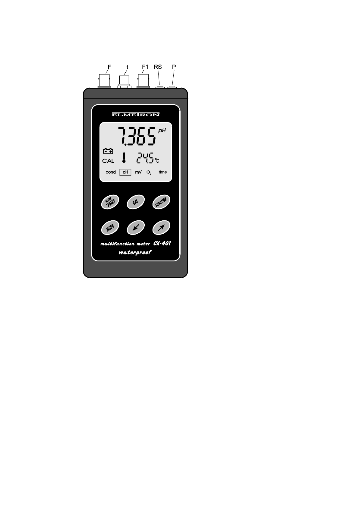
4. OUTSIDE VIEW.
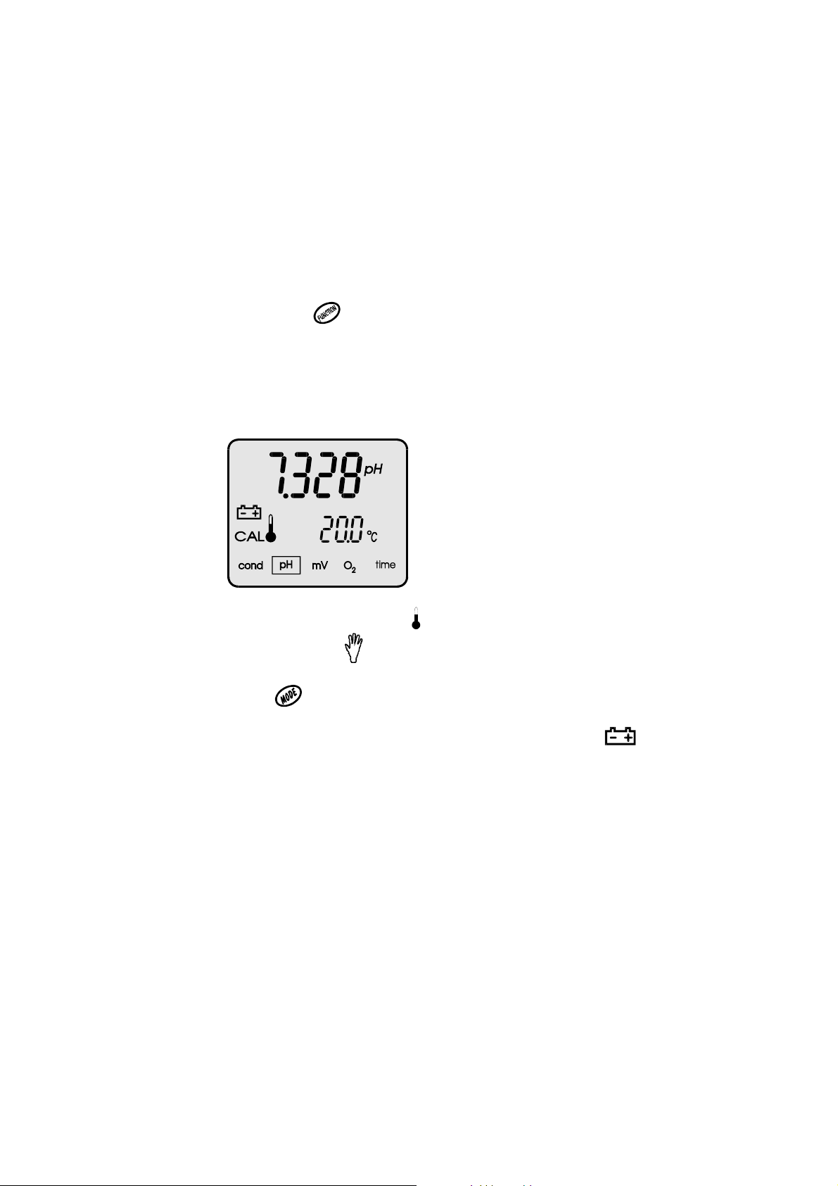
On the front wall of the meter there is a LCD display (pic. 1) on which
depending on the chosen function following symbols are displayed:
- result of the conductivity or salinity measurement;
- result of the pH measurement in pH units;
- result of the mV measurement in mV;
- result of the oxygen measurement in % or mg/l
- time and date.
Choosing the function by
right symbol in the lower part of the display: cond (conductivity), pH, mV, O
button is signalised by displayed frame round the
or
2
time.
Simultaneously with the result a measured temperature value is displayed in oC.
Symbols of the units are displayed by the results. In the oxygen measurement
mode there is possibility of reading the atmospheric pressure value.
Pic. 1.
Beside the temperature value a symbol for automatic temperature
compensation is displayed or for manual. CAL symbol on the left side of the
display informs that the meter is in calibration mode.
After pressing the
button all parameters introduced by the user are
displayed and also the value of atmospheric pressure measurement (in oxygen
measurement function). If the battery should be changed a
.symbol is
displayed.
The keyboard (pic. 2) placed under the display is used for switching the meter
on and off, choosing the measuring function, calibration, entering the
parameters, printing and storing the results in the memory.
- 8 -
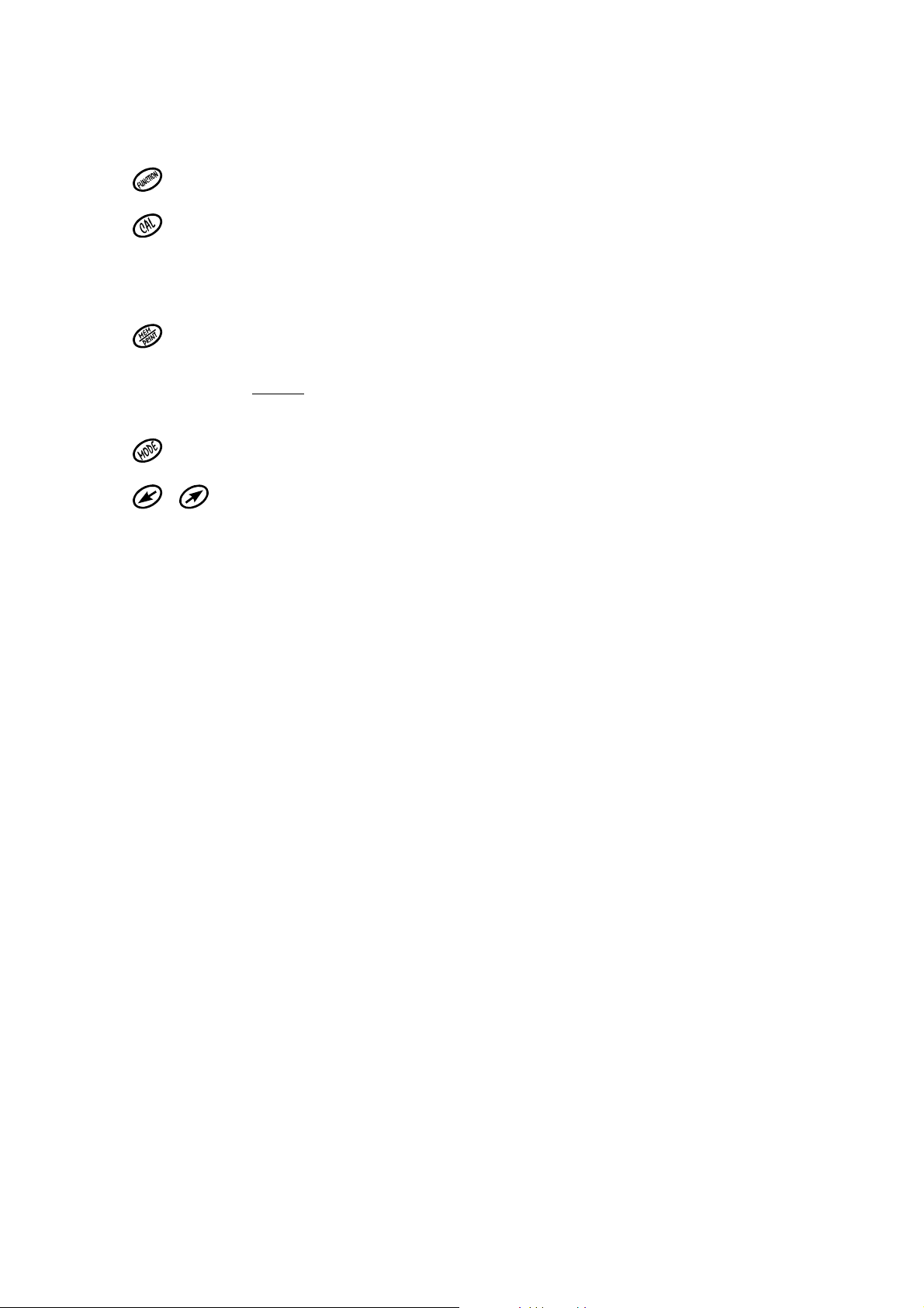
The keyboard has the keys as follows:
- to change the function, and switch the meter on, off.
- short pressing in MODE/P.CAL mode enables choosing points of
calibration to change their value.
- longer pressing of this button enters the calibration mode (CAL symbol
displayed). Short pressing in this mode confirms the calibration result.
- after pressing this button the result is stored, the measuring series
starts or printing begins.
- after longer pressing of this button the stored results reviewing is
possible.
- chooses the entered parameter.
, - buttons used for entering the parameters
In upper wall of the meter there are inputs with below given symbols.
F - BNC-50 connector for connecting the combination pH
electrode, Redox electrode or the oxygen probe
F1 - BNC-50 for connecting the conductivity cell
t - Chinch input to connect the temperature probe
RS - RS-232 input for connecting with PC or printer
P - Power adapter input 9V
- 9 -
Pic. 2.
- 10 -
5. SWITCHING THE METER ON AND OFF
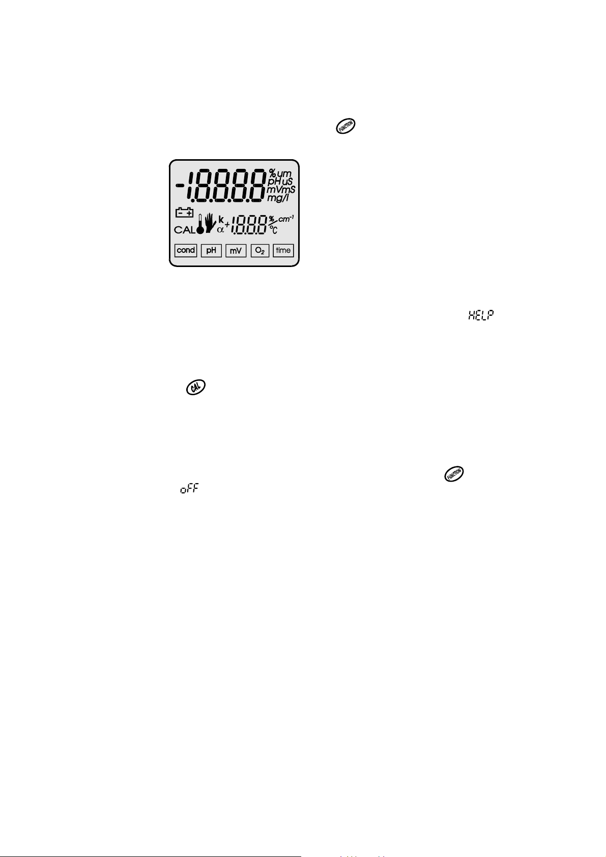
The meter is switched on by pressing the
button. The meter tests the
memory and display on which all symbols are displayed.
Pic. 3
If the test was successful, after about 1.5 s the meter switches it self
automatically to the measuring mode, in which it was switched off. If a sign
will be displayed it means that the meter has lost the factory settings and
requires the service repair. If after the 1,5 s all symbols will be continuously
displayed it informs that the calibration parameters of electrodes or cells were
lost.
After pressing the button the meter will take standard characteristics:
- shift = 0 pH, characteristic slope = 100% for pH electrode;
- constant K = 1.000 cm
- shift = 0% O
, characteristic slope = 100% O2 for oxygen sensor.
2
-1
for conductivity cell;
And will enter the measuring mode. It will be necessary to calibrate the
conductivity cell, pH and oxygen electrodes.
The meter is switched off by pressing and longer holding of the
button till
displaying of the symbol. In case of working on the batteries to save them
the meter switches it self automatically off after the time set by the user from
last pressing of any button. Way of introducing the time is described in the
paragraph number 21. This function is switched off for the time of calibration,
taking the series of measurements, printing the memory content and work with
the power adapter.
- 11 -
6. PREPARATION TO WORK
Before starting the work one should:
- join the power adapter plug to the P input, if work with the power adapter is
planned;
- to BNC-50 input F join the ready to work combination pH electrode, redox
electrode or the dissolved oxygen sensor;
- to BNC-50 input F1 join the conductivity cell;
- in case of using the temperature probe it should be connected with the chinch
temperature input t;
- In case of printing or work with PC join the interface El-401 or cable CP-4XX –
PC with RS input
- switch the meter on by pressing the button.
CAUTION: during pH measurements the conductivity cell has to be
disconnected from the meter or removed from the measured
solution in which the pH electrode is immersed.
6.1. Choosing the kind of temperature compensation
The meter switches it self to the automatic temperature compensation mode
automatically after joining the temperature probe, after disconnecting it the
meter enters the manual temperature compensation mode. In ATC mode near
the displayed temperature a symbol appears. Manual temperature
compensation is indicated by symbol near the value entered by the user, it
may be changed using or keys.
- 12 -
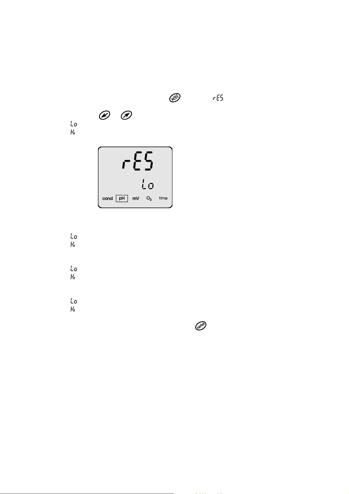
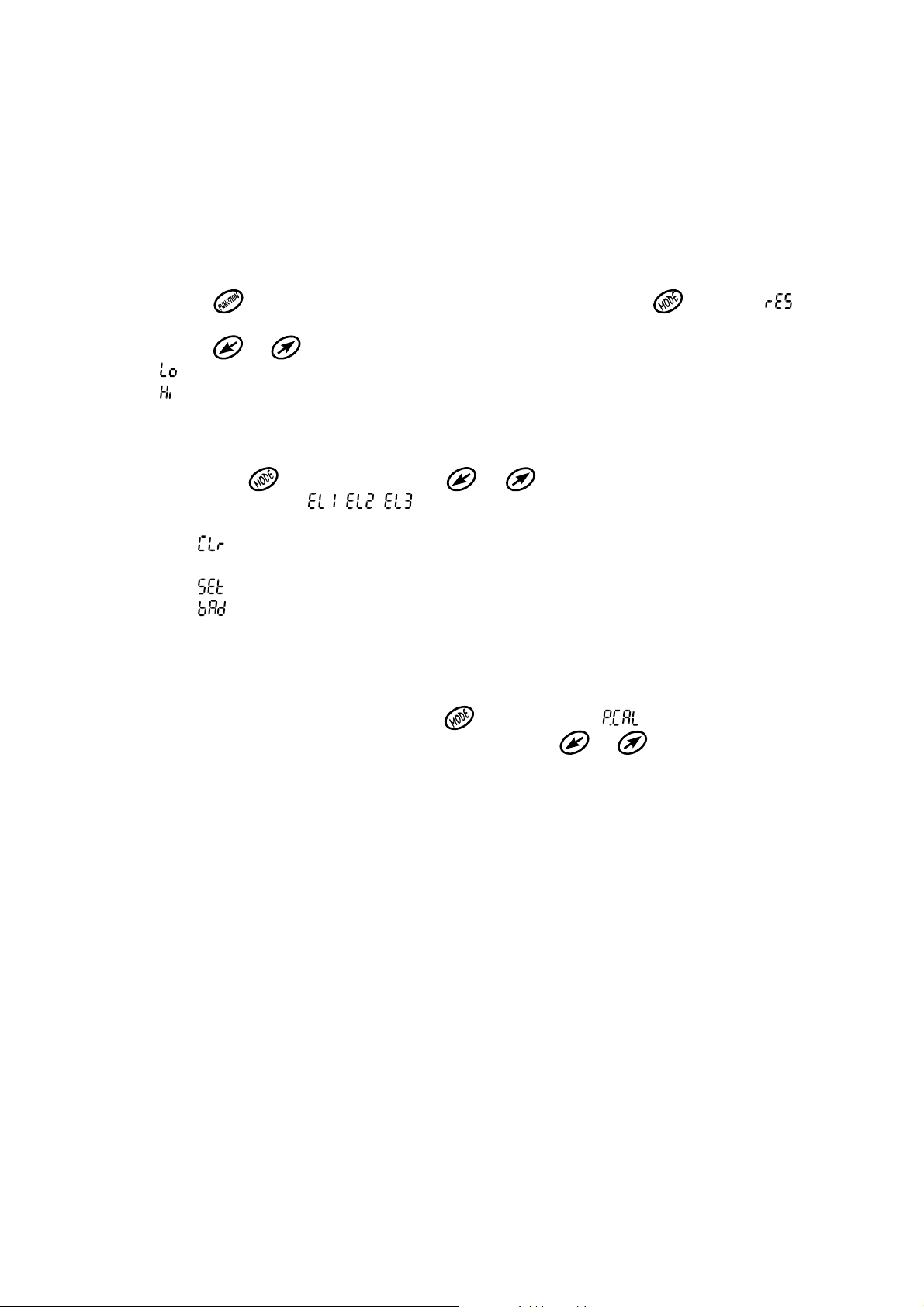
6.2. Changing the resolution of the measurements
The measurement results may be displayed with chosen resolution. To change
it one should:
- in the measuring mode press the button, a (resolution) sign will be
displayed. (Pic. 4)
- Using keys or one may choose:
- (low) resolution of the measurement;
- (high) resolution of the measurement.
Pic. 4
For the pH measurement:
- resolution of the measurement 0.01 pH;
- resolution of the measurement 0.001 pH.
For the conductivity measurement:
- resolution of the measurement 3½ digits;
- resolution of the measurement 4½ digits.
For the oxygen measurement:
- resolution of the measurement 1% or 0,1mg/l;
- resolution of the measurement 0.1% or 0.01 mg/l.
Return to the measurement mode by pressing
button.

- 13 -
II. pH measurement

- 14 -
7. PREPARATION OF THE pH ELECTRODE
The electrode should be prepared to work according to the producer
instructions. If the instructions weren’t given please follow the steps:
- new electrode should be put into distilled water or in saturated KCl solution
for about 5 hours:
- Before starting the measurements protecting rings (if used in this kind of
electrode) should be removed. The ring placed on the junction – lower part
of the electrode should be moved up along the electrode’s body and the
upper, which protects the KCl refilling hole, down along the body.
Removing the lower ring is essential, in other case the electrode won’t
measure.
Upper ring should be removed during measurements of high temperature
solutions or to protect the junction during measurements in solutions with
deposits or oils;
- during measurements in laboratory it is advisable to use an electrode holder;
- after every measurement the electrode should be washed in distilled water;
- excess of liquid on the electrode should be removed by gentle touching the
glass with a tissue paper;
- after work the electrode should be stored in one of the above given solutions.
The protecting rings should be moved on the junction and upper hole;
- in case of long breaks between the measurements the electrode should be
stored, after drying, in the packaging;
- after taking the electrode of the package the eventual deposit should be
removed using water;
- before using the electrode it should be placed in distilled water for about 2
hours;
- if the construction of the electrode enables refilling the electrolyte, it should
be controlled and refilled periodically by the upper hole in the electrode’s
body (usually as the electrolyte a KCl solution is used).
CAUTION: storing of the electrode in distilled water shortens it’s life time and
may cause shifting of the zero point.

- 15 -
8. CALIBRATION OF THE pH ELECTRODE
Before starting the measurement with new electrode, after long-lasting using, or
before making measurements which require higher accuracy the electrode
connected with the meter should be calibrated. Results of measurements done
without calibration will have a great error. The calibration is done on the buffer
solutions. It depends on comparing pH value of the buffer solutions with the
value displayed by the meter and next automatic introduction of correction
which is taken into consideration during measurements. The calibration should
be periodically repeated because during work the parameters of the electrode
are changing what influences the accuracy. The frequency of this procedure
depends on the demanded accuracy, number of the measurements carried out,
conditions in which the electrode was used, temperature and value of the
measured solutions. When the highest accuracy is required it is recommended
to use sample solutions with certificates. In technical usage buffer solutions are
used with lower accuracy but mostly with total values ex. 2.00 pH; 4.00 pH etc.
In this manual to make it easier a buffer solution name was used for both buffer
and sample solutions. For accurate measurements it is necessary to use fresh
good quality buffers.
The first action taken before the calibration is entering the values of used pH
buffer solutions to the meter’s memory. This should be done before the first
calibration and repeated in case of changing the used buffers to other values.
During the calibration after immersing the pH electrode and temperature probe
the meter automatically detects the value of the used buffer, if it was earlier
stored in the meter’s memory.
There is possibility of calibration in minimum 1 buffer solution and maximum in 5.
The more points of calibration is used the higher is the accuracy in the whole
measuring range.

- 16 -
Calibration in one buffer solution can’t ensure high accuracy. If only one buffer
solution is used it’s value should be close to the forecasted value of measured
solution. If the required accuracy isn’t very high and the measurements will be
done in the whole range the one point calibration should be done with buffer
solution close to 7.00 pH. Thanks this the so called zero electrode shift will be
eliminated. In other points a standard characteristic will be taken from the
meter’s memory. This characteristic corresponds with theoretical efficiency of
the pH
electrode
If measurements are done both in acids and alkalis and the measurements are
not done at the ends of measuring range it is enough to calibrate the electrodes
in 3 buffer solutions with values in range given in table 2 – calibration points 2, 3
and 4. In case of accurate measurements in the whole range it is recommended
to calibrate the electrode in all 5 points given in the table. IN CX-401
characteristic of the electrodes is approximated linearly between the calibration
points.
Starting the calibration under one of the electrode numbers does not
remove the set buffer values, but irreparably removes the electrode
characteristic stored under this number.
There is no possibility of calibrating only one point, leaving the rest of
data from the last calibration.
CX-401 enables independent storing of 3 characteristics of pH electrodes. This
feature is especially useful when fast replacing of the electrodes is necessary or
when it was broken. Those electrodes should be earlier calibrated and brought
into memory under following symbols , , .

- 17 -
The order of using the buffer solutions is freely chosen.
The user may choose two independent ways of action:
1. enter the value of pH buffer solutions depending on the actually used
buffers, in the range given for each point of calibration;
2. use the values of pH sample solutions entered to the memory by the
manufacturer. Those values are in conformity with the NIST norm. This
type of calibration switches on the automatic correction introduction
connected with the change of sample solution along with temperature
changes.
Choosing the second option makes the calibration much easier. The user
doesn’t need to warm up or cool down the sample solutions to the temperature
given by the user. This option includes some simplifications and when very high
accuracy is required it shouldn’t be used. The meter stores independently 5
values of the buffers for each of the calibration modes described above.
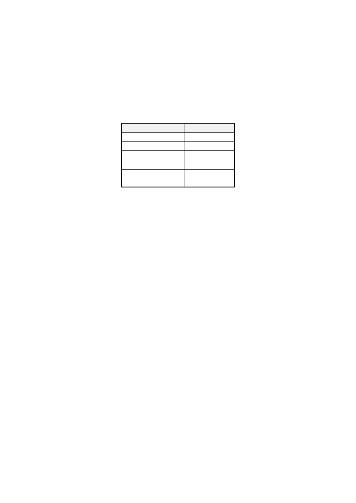
8.1. Introducing the pH values of buffer solutions.
Values of the buffer solutions set by the producer in the meter’s memory are
given in the table 1.
Point of
Calibration
Resolution
0,001
Resolution
0,01
1 1,675 1,68
2 4,002 4,00
3 6,881 6,88
4 9,225 9,22
5 12,627 12,63
Table 1
If the values of used buffer solutions are different than the given above the user
may change the set values.
- 18 -
Range of possible changes is given in the table 2. There is possibility to
introduce the values of buffer solutions with two or three decimal places.
The meter doesn’t allow for introducing pH values in ranges other than
those given in the table 2.
Table 2.
Calibration point Range
1
2
3
4
5
0,800 ÷ 2,100
3,900 ÷ 4,100
6,800 ÷ 7,100
8,900 ÷ 9,400
11,500÷
14,000
The values of pH buffer solutions entered by the users are stored in the
meter’s memory till their changing to others.
Some of the sample solutions made according to norms may differ between on
the third decimal place. In very accurate measurements the user may not use
the mode with values of sample solutions according to NIST, but the mode
which enables changing the values of stored buffers. Before calibration one has
to change them to the accurate value of used sample.
The range of introducing the pH values of the buffer solutions in the individual
points of calibration is quite wide what enables to use buffer solutions with
values which differ from the ones set by the producer. For example buffers with
value 2,00 pH; 7,00 pH; 9,00 pH; and 12,00 pH may be used. In every case the
introduced buffer solution will be automatically recognised by the meter.

- 19 -
Together with the temperature change value of the pH buffer solution changes.
The producers often give the values of the solutions in few temperatures. This
data may be used and the meter may be calibrated in other temperature than
20 oC, by introducing to the meters memory value of the buffer which responds
to the chosen temperature.
8.2. Automatic change of the pH value of buffer solution.
In this mode 5 constant sample solution values, according to NIST, are used. In
the meter’s memory a table with dependence between the temperature
and pH values for this 5 sample solutions is stored. This dependence is
showed in the table 3. Those values are taken into consideration when the
calibration is done in other temperatures. Values between the points are
approximated linearly.
The highest accuracy may be obtained only when the pH values of the buffer
solutions are identical as in the table.
If there are some differences between the values given in the table and values
given by the producer of buffer solutions, one should judge weather the error
which will occur during calibration with automatic correction of the value won’t
be to big. If yes one should resign from using this option.
The range of the temperatures, taken into consideration during introducing the
correction, is 0 to 60 oC, and can’t be exceeded.
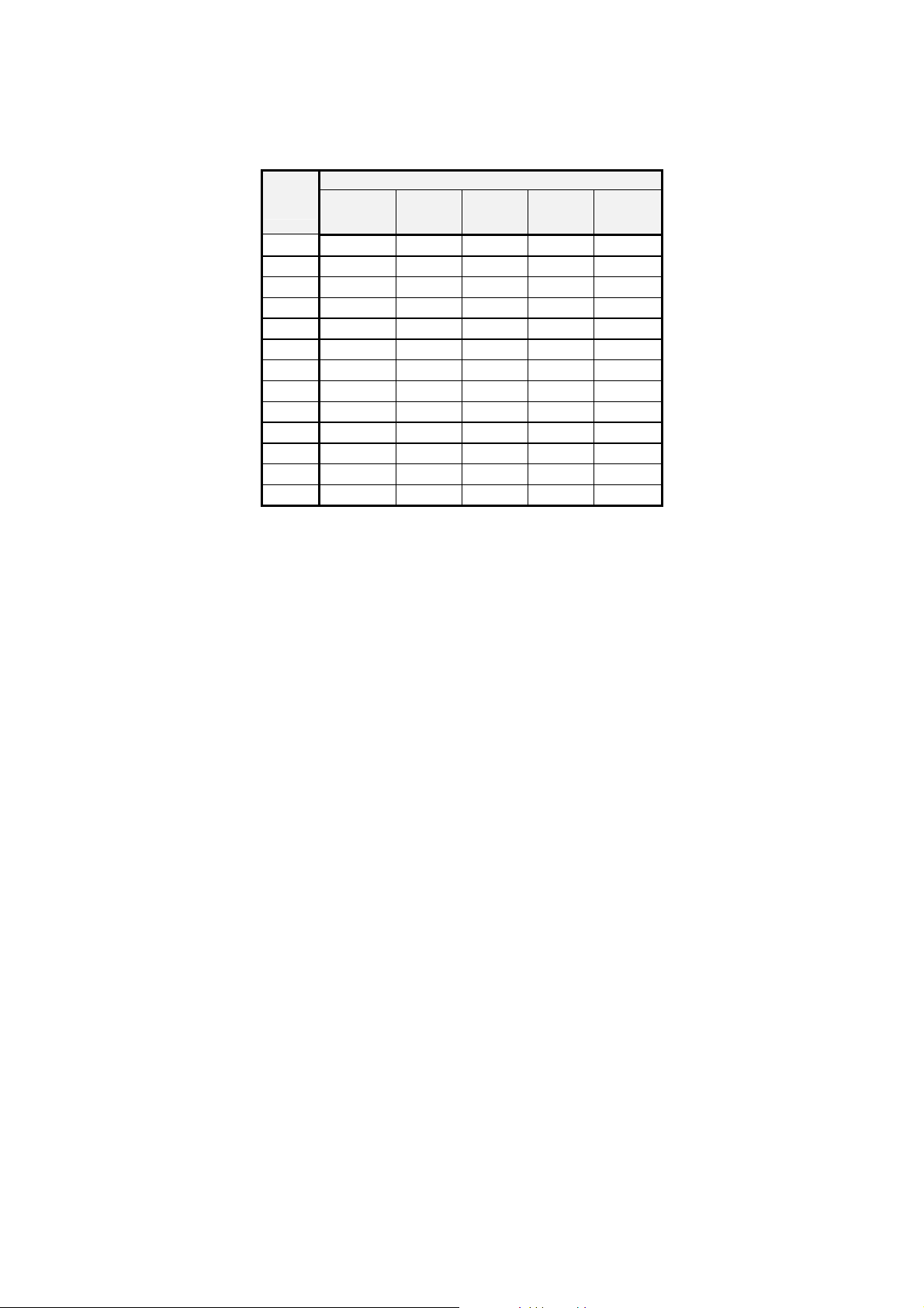
Table 3.
- 20 -
Temp.
0
C
1
oxalate 2 phthalate3 phosphate4 di-sodium
Kind of buffer solution
tetraborate
calcium
hydroxide
0 1.666 4.003 6.984 9.464 13.423
5 1.668 3.999 6.951 9.395 13.207
10 1.670 3.998 6.923 9.332 13.003
15 1.672 3.999 6.900 9.276 12.810
20 1.675 4.002 6.881 9.225 12.627
25 1.679 4.008 6.865 9.180 12.454
30 1.683 4.015 6.853 9.139 12.289
35 1.688 4.024 6.844 9.102 12.133
40 1.694 4.030 6.838 9.063 11.984
45 1.700 4.047 6.834 9.038 11.841
50 1.707 4.060 6.833 9.011 11.705
55 1.715 4.075 6.834 8.985 11.574
60 1.723 4.091 6.836 8.962 11.449
5
- 21 -
8.3. The actions during calibration
One should:
a. Choose the resolution with which the buffer solution value will be introduced.
Depending on the fact weather the buffer solutions have the pH value given
with 2 or 3 decimal places one should choose the right resolution.
Using button choose the pH function, next press the button a
(resolution) sign will be displayed.
Using or buttons choose:
- (low) resolution of the measurement 0.01 pH;
- (high) resolution of the measurement 0.001 pH.
b. Choose the electrode number under which the parameters of calibration will
be stored.
Press the
button, than using or
buttons choose the electrode
number (symbols , , ), under this number the calibration results will
be stored. Above the electrode number following signs will be displayed:
- under this number there is no characteristic stored and producers
values are provided.
- under this number there are values of last calibration stored.
- the last calibration showed that the electrode is loosing it’s
efficiency and in short time it’s calibration won’t be possible
c. Choose or block the function of automatic correction of the change of pH
value of buffer solution with the temperature.
To do so one should press the button than a symbol (points of
calibration) will be displayed, (pic. 5) next using or
buttons choose:

- 22 -
– automatic change of the stored pH value of the buffer solution by
it’s temperature change according to table 3.
– setting the value of the buffer solution in the range given in table 3.
Pic. 5
After choosing the symbol one should press the button and start the
calibration in buffer solutions according to point e and chapter 8.4.
After choosing the act according to the point d.
d. After choosing the (user setting) symbol one should start checking and
eventually changing the stored values of calibration points. To do so one
should press the button. In the lower row a symbol will be displayed,
point one of calibration, and in the upper row value of the buffer. (pic. 6) If
one uses buffer solution with value a bit different than this displayed one,
using or
buttons bring the displayed value to the value of used
buffer solution.
Range of changes for each calibration points is given in the table 2.
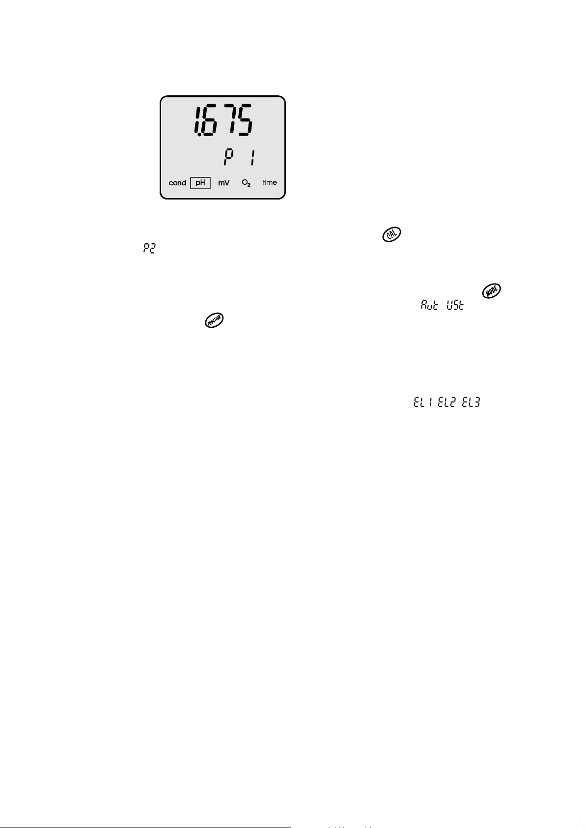
- 23 -
Pic. 6.
To pass to the second point of calibration press the button in the lower
row a , symbol will be displayed (point 2) and in the upper row the stored
in this point value of buffer solution. When checking or changing the value
in the next steps please follow the instructions given above.
After the end of introducing the pH values of buffer solutions using the
button return to the choosing the calibration points mode ( / ,) or by
next pressing the enter the pH measuring mode.
During next calibrations if the values of the previously used buffer
solutions haven’t changed the actions described in this point may be
omitted.
e. Prepare the electrode for work acting according to it’s producer instructions,
than mark it with the number chosen in the meter (symbols , , ).
- connect the prepared combination electrode and temperature probe to the
right connectors (F and t) in the meter (pic. 2);
- if the function of automatic correction of the influence of temperature on
pH value of the buffer solution isn’t used measure the temperature of the
buffer solutions and bring it to the temperature given by it’s producer, so to
reach the value set in the meters memory. The order of using the buffer
solutions may be chosen freely.
 Loading...