

Page 1

WATERPROOF
CONDUCTIVITY METER
CC- 411
USER’S MANUAL
Page 2

Page 3

USER’S MANUAL
WATERPROOF
CONDUCTIVITY METER
CC-411
Before use please read the instruction carefully.
Page 4

Page 5

CONTENTS
I. INTRODUCTION 1
1. Exploitation notices 3
2. Characteristics of the meter 4
3. What is the meter designed for 5
4. The outside view 6
5. Switching the meter on and off 9
6. Preparation to work 10
6.1. Choosing the measuring function and unit 10
6.2. Choosing the kind of temperature compensation 11
6.3. Entering the temperature value for manual temperature
compensation 11
II. CONDUCTIVITY MEASUREMENT 13
7. Basic information about the conductivity measurement 15
8. Choice and maintenance of the conductivity cell 16
8.1. Choice of the conductivity cell 16
8.2. The conductivity cell maintenance 17
9. Calibration of the conductivity cell 18
9.1. Calibration without the standard solution 18
9.2. Calibration with use of standard solution 19
10. Conductivity measurement 22
10.1. Conductivity measurement without temperature compensation 22
10.2. Conductivity measurement with automatic temperature
compensation 23
10.3. Conductivity measurement with manual temperature compensation24
10.4. Conductivity measurement in honey 25
10.5. Preparation of the measurement sample 25
11. Salinity measurement 26
11.1. Salinity measurement with conversion to NaCl 27
11.2. Salinity measurement with conversion to TDS 27
III. TEMPERATURE MEASUREMENT 29
12. Temperature measurement 31
IV. OTHER 33
13. Readout of the software version number 35
14. Power source and changing the battery 36
15. Technical data 37
16. Equipment 38
Page 6

Page 7

- 1 -
I. INTRODUCTION
Page 8

- 2 -
User’s manual for CC-411 conductivity meter v5.30
Page 9

- 3 -
1. EXPLOITATION NOTICES
Dear User!
We present you a device distinguished by accuracy according to the
technical data and by a high stability of displayed results. We believe that
measurements will not cause you any trouble and that the meter will operate
without any inconvenience.
Using good-quality cells and replacing them if necessary ensures obtaining
high measuring parameters. We want to call your attention to the fact, that
this equipment has much shorter working life than the meter.
In case of conductivity measurements it is important to choose the cell with K
constant value adjusted to the measuring range. Improper selection may
cause increase of the readout error.
The essential feature of our products is their low failure frequency. However,
if your meter fails, our firm will immediately perform its warranty repair.
We wish you pleasant and trouble-free work with our meter.
Page 10

- 4 -
User’s manual for CC-411 conductivity meter v5.30
2. CHARACTERISTICS OF THE METER
The CC-411 conductivity meter belongs to the newest generation of
measuring devices which ensure high accuracy and repeatability of readings
and is easy in use. Two kinds of power source: battery and power adapter,
enable work in the field and long-lasting measurements in the laboratory.
Electronic elements of the newest generation used in the meter have made
its memory independent from power supply and have ensured very low
power consumption what greatly prolongs the operation time on 1 battery.
The meter is equipped with large custom LCD display, which displays the
conductivity or the temperature value. Waterproof housing makes working in
difficult conditions possible. Minimised size and weight make the meter very
handy especially during the field work.
Main features of CC-411 are:
- high accuracy and stability of readings;
- calibration of the conductivity cell by introducing the K constant or on
standard solutions;
- possibility of determining the K constant of the cell;
- automatic and manual temperature compensation;
- storing parameters in non-volatile memory;
- co-operation with Pt-1000 temperature sensor;
- system protecting the meter against damages caused by connecting the
battery inversely;
- information about the battery condition (
)
;
- automatic switch off function.
Page 11

- 5 -
3. WHAT IS THE METER DESIGNED FOR
CC-411 waterproof conductivity meter is a precise and easy-to-use meter
designed for measurements of conductivity in µS/cm or mS/cm. The meter
may be also used for accurate temperature measurement of solutions and air
in °C. It is useful both for work in the field and measurements in the
laboratory.
Waterproof housing enables work in difficult weather conditions or in humid
environment.
The CC-411 conductivity meter is used in food, chemical, pharmaceutical and
power industries, in water treatment stations, laboratories, agriculture,
universities, scientific laboratories etc.
The meter is prepared to work with many types of conductivity sensors (with
wide ranged K constant) equipped with BNC-50 connector. CC-411 cooperates with Pt-1000 temperature probe with Chinch connector.
Page 12
- 6 -
User’s manual for CC-411 conductivity meter v5.30
4. THE OUTSIDE VIEW
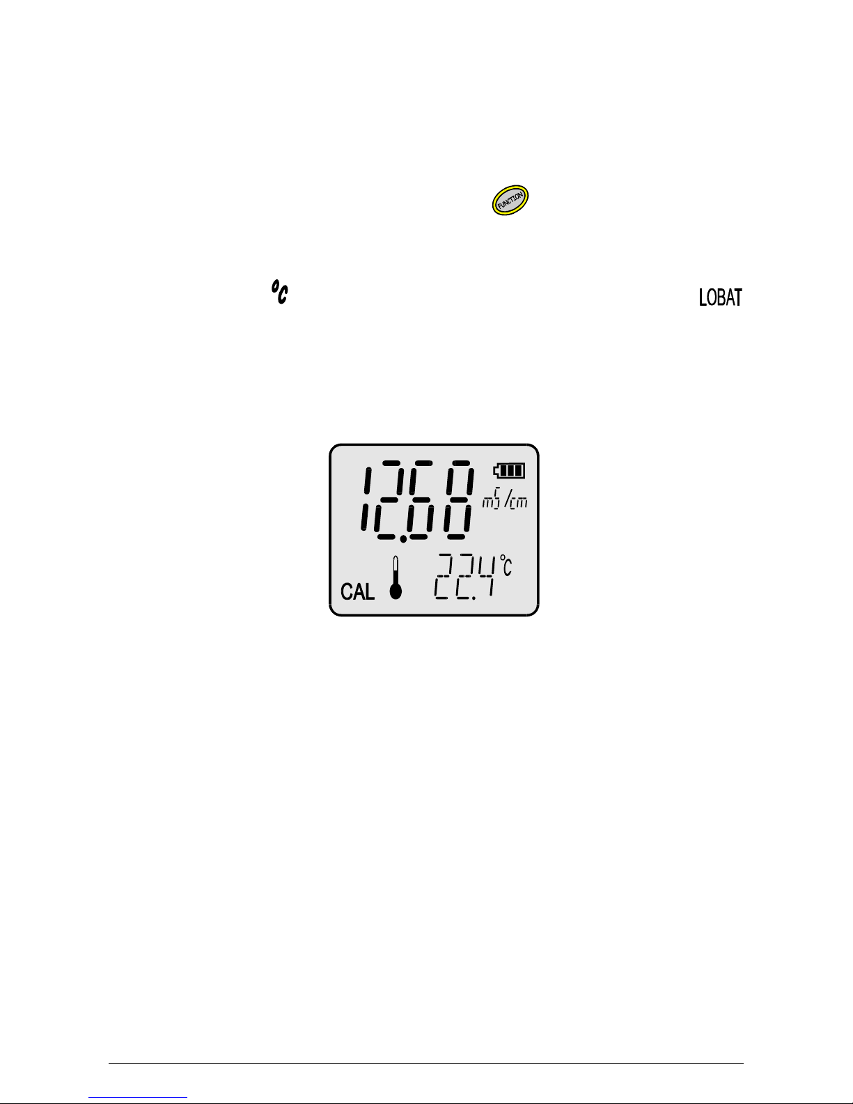
On the front wall of the meter there is an LCD display (Pic.1) on which,
depending on the chosen function, the result of conductivity measurement in
µS/cm or mS/cm or temperature measurement in oC is displayed:
A particular function is chosen by pressing the button.
Symbols of units are displayed next to the result.
In case of disconnecting the temperature probe the meter switches to the
manual temperature compensation mode. Next to the result there will be
displayed blinking symbol. If the battery should be changed, a
symbol is displayed. The keyboard placed under the display is used for
switching the meter on and off, choosing the measuring function, calibration
and entering parameters.
Pic.1
The CAL symbol on the left side of the display informs that the meter is in
calibration mode.
Page 13

- 7 -
The keyboard (pic. 2) placed under the screen has the following keys:
- switching the meter on and off.
- pressing shortly enters the unit choosing mode (with the
button); pressing and holding returns to the measurement
mode.
- holding this button enters the calibration mode (CAL symbol
displayed).
, - buttons used for entering the parameters
In the upper wall of the meter there are inputs placed with the symbols given
below:
F1 - BNC-50 input for connecting the conductivity cell;
t - Chinch input for connecting the temperature probe;
P - the power adapter input.
Page 14

- 8 -
User’s manual for CC-411 conductivity meter v5.30
Pic. 2
Page 15
- 9 -
5. SWITCHING THE METER ON AND OFF
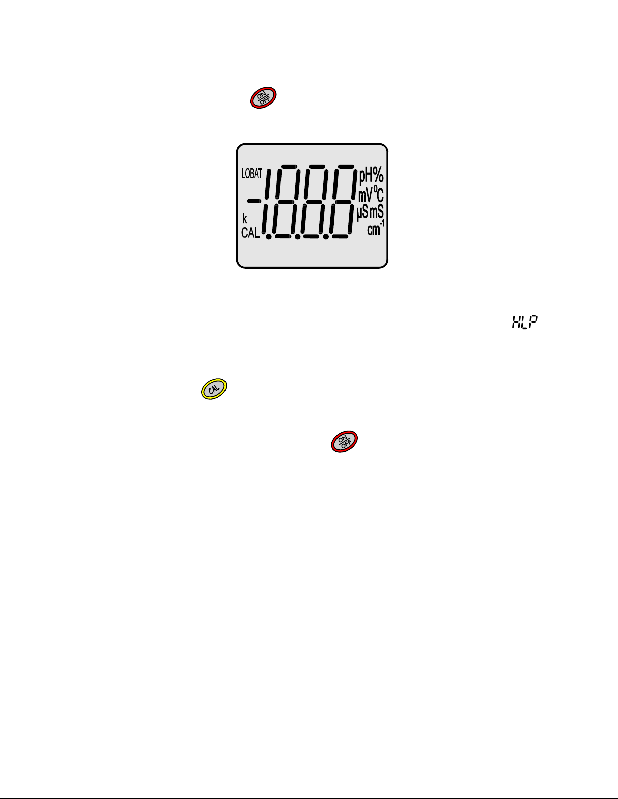
After switching it on with the
button, the meter tests the memory and the
display on which all symbols are displayed after switching it on (Pic. 3).
Pic. 3
If the test ends successfully, after about 1.5 s the meter switches
automatically to the measuring mode, in which it was switched off. If a
sign is displayed, it means that the meter has lost the factory settings and
requires service repair. If after 1,5 s all symbols are continuously displayed, it
informs that the calibration parameters of the cell have been lost.
After pressing the button the meter adopts the K constant of the
conductivity cell K=1.000 cm-1 and enters to the measuring mode. It will be
necessary to calibrate the conductivity cell.
The meter is switched off by pressing the
button. In case of working on
batteries, in order to save them, the meter switches automatically off after 10
minutes of non-use. This function is automatically deactivated when working
with power adapter.
Page 16
- 10 -
User’s manual for CC-411 conductivity meter v5.30
6. PREPARATION TO WORK
Before starting measurement:
- connect the power adapter plug to the P input, if work with the power
adapter is planned;
- join the suitable conductivity cell to BNC-50 input (F1);
- in case of using the temperature probe it should be connected with the
temperature input Chinch (t);
- switch the meter on by pressing the button.
6.1. Choosing the measuring function and unit
CC-411 enables measurement of:
- conductivity at µS/cm or mS/cm converted to 25oC;
- salinity in g/l converted to NaCl (accordinfg to actual slope);
- salinity in g/l converted to TDS (with use of the W
TDS
coefficient);
- conductivity of honey at µS/cm or mS/cm converted to 20oC;
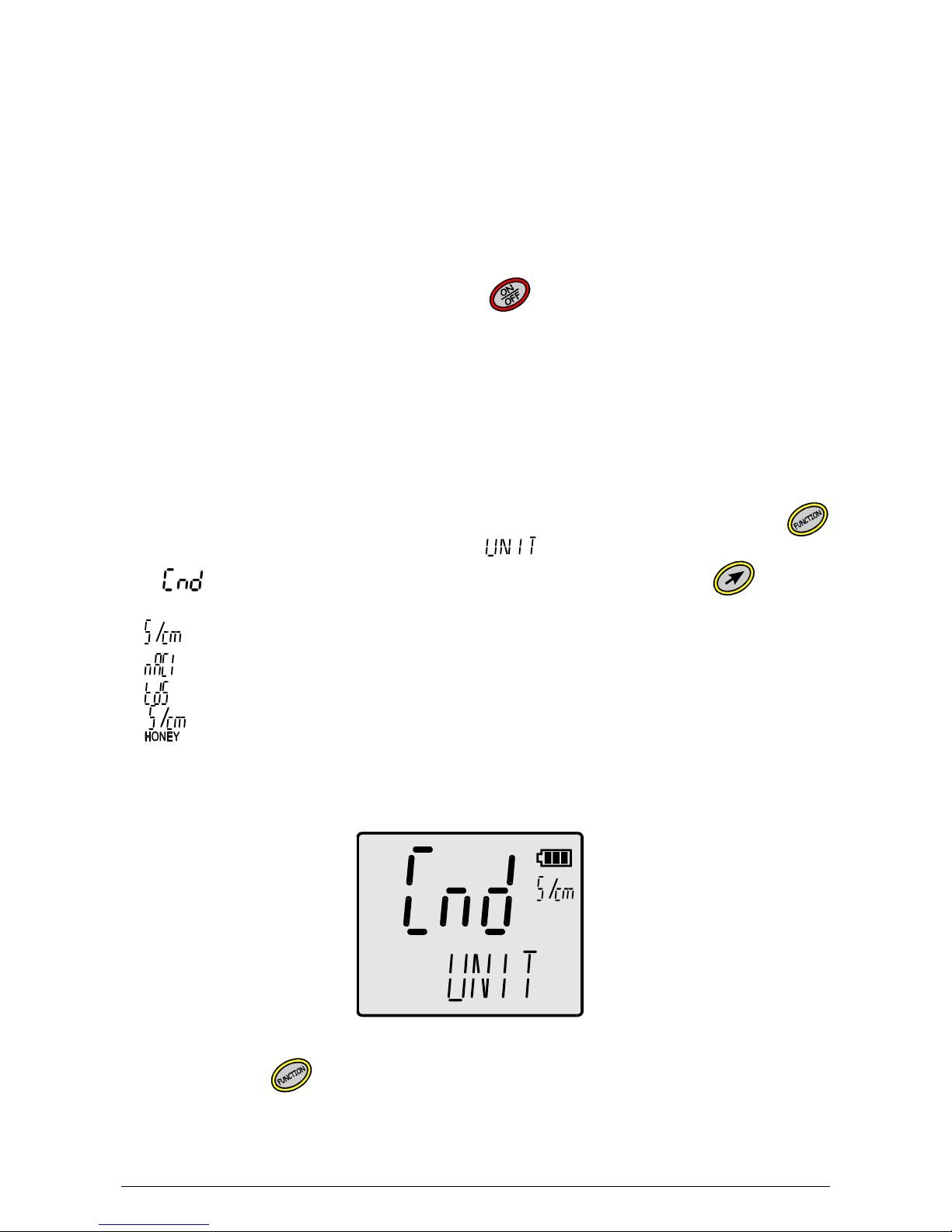
The unit is chosen in the measuring mode by pressing and holding the
button, in the buttom row displays the symbol and in the upper row -
the (conductivity) symbol (Pic.4). Next, by pressing the
button,
choose:
- - measurement in µS/cm lub mS/cm converted to 25oC;
- - measurement in g/l converted to NaCl;
- - salinity in g/l converted to TDS;
- - measurement in honey in µS/cm or mS/cm converted
to 20oC.
Pic. 4
By pressing the
button return to the measuring mode.
Page 17
- 11 -
6.2. Choosing the kind of temperature compensation
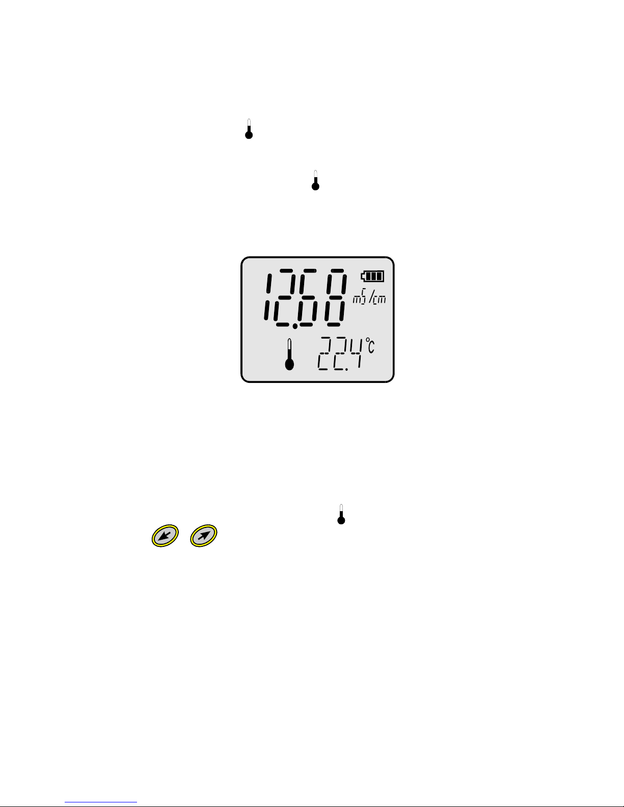
The meter switches to the automatic temperature compensation mode
automatically after connecting the temperature probe. Next to the
temperature reading the symbol appears. The measurement will be
compensated to the value of temperature measured by the probe
Disconnecting the temperature probe switches the meter to the manual
temperature compensation mode (the symbol disappears) and the value of
the temperature entered by the user will be adopted for compensation.
Pic. 5
6.3. Entering the temperature value for manual temperature
compensation
To enter the temperature value for manual temperature compensation:
- disconnect the temperature probe (the symbol disappears);
- with the , buttons enter the requested temperature value;
Page 18

- 12 -
User’s manual for CC-411 conductivity meter v5.30
Page 19

- 13 -
II. CONDUCTIVITY MEASUREMENT
Page 20

- 14 -
User’s manual for CC-411 conductivity meter v5.30
Page 21

- 15 -
7. BASIC INFORMATION ABOUT THE CONDUCTIVITY MEASUREMENT
The conductivity measurement is based on applying electric current with
proper voltage and frequency between two electrodes and measuring it. In
CC-411 the frequency depends on the measuring range and may vary from 1
kHz up to 12 kHz. The voltage is dependent from the kind of the measured
liquid, its concentration and temperature. The conductivity result informs
indirectly about the salt concentration in the measured liquid. The greater it
is, the higher conductivity (KCl, NaCl). This dependence doesn’t concern all
of the solutions. In some cases, after exceeding certain salinity value
conductivity starts decreasing. Temperature has also a great influence on the
results of conductivity measurement, which increases together with the
temperature rise.
The electrodes’ surface and the distance between them have decisive
influence on the K constant value of the cell. This value has a great influence
on the accuracy of the measurement. Depending on the measured
conductivity value cells with K constant = 0.05 cm
-.1
up to 1.500 cm
-.1
are
used. During measurement the meter multiplies the measured value by the K
constant introduced to the meter’s memory and displays the result in units of
conductivity (µS/cm or mS/cm). Shortened symbol of the unit is displayed next
to the result (µS or mS). Conductivity is affected by the temperature and
salts concentration. In order to enable comparing of the results, measured
value is counted by the meter to the value which corresponds to measurement
in 25 0C. Measurement in this temperature is the most accurate. In other
temperatures there is temperature compensation used, which means that the
meter takes currently measured temperature and α coefficient into
consideration. This coefficient describes how much the result will change
when the temperature change is 1 0C. The α coefficient in this meter is
constant and equal 2% / 0C. This is the closest value to that of most of the
salts in 25°C. For example if measurements are made in liquid of temperature
coming to 30 0C, the result change will total up to 5 x 2% = 10%.
The conversion is made automatically and this change is counted into the
result. The conductivity measurement should always be treated as burdened
with a certain error, which depends on the conductivity cell (its linearity) and
temperature. When measurements are not made in the reference
temperature, the error is dependent mainly on the α coefficient, which is
affected by the temperature and concentration changes.
Page 22
- 16 -
User’s manual for CC-411 conductivity meter v5.30
8. CHOICE AND MAINTENANCE OF THE CONDUCTIVITY CELL
8.1. Choice of the conductivity cell
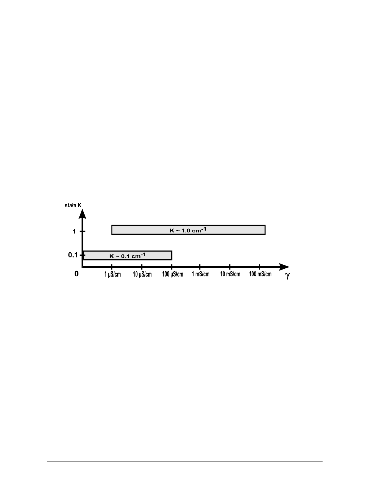
Conductivity in CC-411 meter can be measured in range
0 – 100 mS/cm. The meter co-operates with conductivity cells with K constant
= 0.050 ÷ 1.500 cm-1 and equipped with BNC-50 connector. Depending on
the required measuring range it is necessary to choose appropriate cell with K
constant which enables obtaining accurate results. Beyond the range the cell
looses its linearity and the results have greater error. Accurate measurements
in the whole range are possible with use of 2 different conductivity cells.
In range 1 – 100 mS/cm the standard conductivity cell with K constant =1 cm
-
1
should be used.
For measurements of ultra pure water with conductivity below 1 µS/cm a cell
with K constant = 0.1 cm-1 should be used.
Depending on the expected measuring range, choose the appropriate cell
using the chart below (Pic.6).
Pic. 6. Dependence between the measuring range and of applied conductivity
cells.
Page 23

- 17 -
8.2. The conductivity cell maintenance
In order to receive stable results, it is advisable to store the cell in water for a
few hours before the measurement, this is especially required in case of
distilled water measurements.
The conductivity cell maintenance consists mainly in accurate washing the
inside of the measuring cell with distilled water. The platinum electrodes must
not be cleaned mechanically, because this results in rubbing off the platinum
layer, what can cause decreasing of accuracy, lowering of stability and
changing of the K constant.
Measurements of liquids with oils and heavy-sediment content may cause
platinum contamination, make the measurement impossible and irreparably
damage the electrodes. In case of fat content in the measured liquids it is
possible to clean the electrodes by immersing the cell in acetone, chloroform,
fourhydrofuran or detergent.
Certain norms recommend universal liquid for cleaning cells. This is a
mixture of equal parts of isopropyl alcohol, ethyl ether and hydrocholic acid,
diluted with water in 1:1 ratio.
Breaking of the measuring cell hinders any further measurements due to
significant change of the K constant, unstable results and increase of the
dependence of the result on the position of the cell in the measuring vessel.
The cell should be immersed in such a way for the solution to fill it up and not
to include any air bubbles (single bubbles or silver coating). It is essential for
obtaining accurate results of measurements. The best way is to immerse the
cell, make a few vertical moves and thus to remove air bubbles through holes
in the upper part of the cell. If the air bubbles appear each time after the cell
has been immersed and they are difficult to remove, it is advisable to
immerse the cell in a water – washing up liquid mixture, what will lower the
surface tension and disable air bubbles to stick to the surface of the cell walls
or electrodes. After such action the cell should be washed accurately in
distilled water.
Page 24
- 18 -
User’s manual for CC-411 conductivity meter v5.30
9. CALIBRATION OF THE CONDUCTIVITY CELL
Characteristic feature of every conductivity cell is its K constant. Before
displaying the result on the display the value is multiplied by the K constant
value. The value of the K constant depends on the size of the electrodes’
surface and the distance between them. If the user keeps the cell clean, the
K constant does not change. In case of contamination of the surface of the
electrodes, the K constant will change.
Calibration may be performed without the sample solution, by entering the
value of the K constant of the cell given by the manufacturer to the meter’s
memory (we recommend this kind of calibration) or with use of standard
solution with known conductivity, to determine the K constant.
The K constant is precisely determined by the cell manufacturer and
using this value will be the most reliable.
In case of calibration performed by the user, fresh, accurately prepared
standard solution is required. Additionally it has to be accurately
thermostatic to 250C. If the conditions won‘t be kept the calibration may
be burdened with error.
9.1. Calibration without the standard solution
The meter has a possibility of calibration without the use of standard solution.
For such calibration, it is necessary to know the K constant of the conductivity
cell. This value may be given by the cell manufacturer or may be determined
using the CC-411 meter after calibrating it in the standard solution.
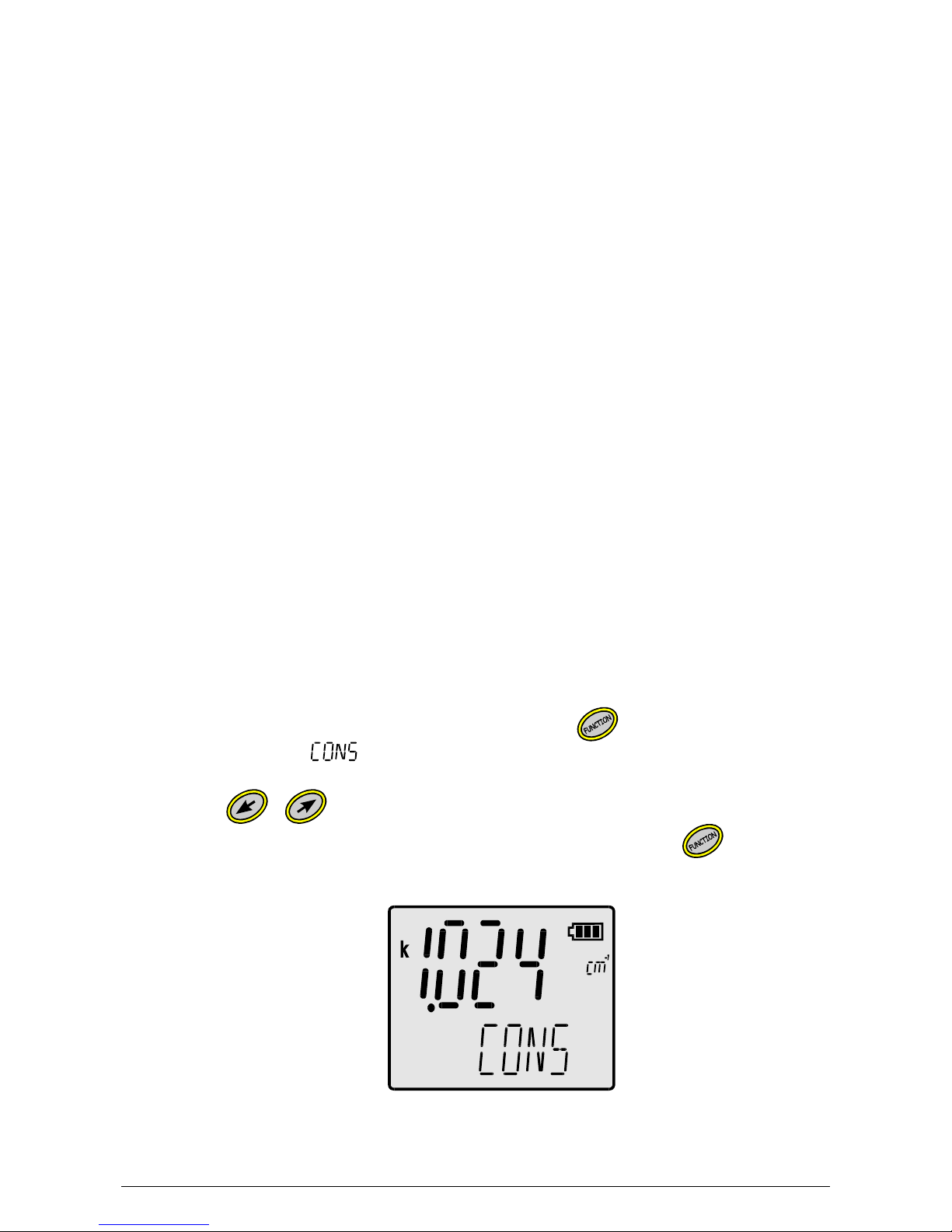
In order to calibrate:
- in the conductivity measuring mode press the button till the moment
of displaying the symbol in the bottom row and the k symbols and
the value of the K constant introduced earlier in the upper row.
- with the , buttons enter the value of the K constant;
- return to the measuring mode by pressing and holding the
button.
Pic. 7
Page 25
- 19 -
9.2. Calibration with use of standard solution
The meter enables one-point calibration in a freely chosen standard solution,
to determine the K constant of the cell. In order to decrease the error, it is
recommended to use solutions with value close to the estimated value of
measurement. It is required to use standard solutions of a high quality.
9.2.1. Entering the standard solution value
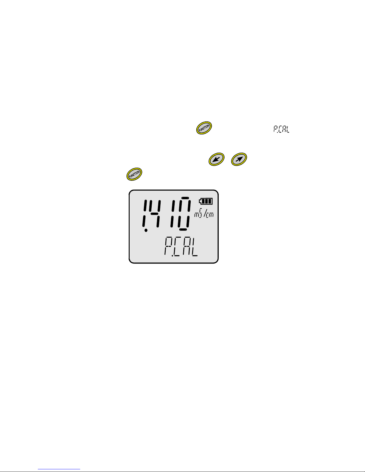
To enter the standard solurion value:
- choose the measurement unit according to the point 6.1;
- in the measurement mode press the button until the symbol
displays in the bottom row abd the upper row displays the current
calibration point value pic. 8);
- enter new standard solution value with the , buttons;
-
press and hold the button to return to the measurement mode.
Pic. 8
Page 26
- 20 -
User’s manual for CC-411 conductivity meter v5.30
9.2.2. Calibration without the temperature compensation
Accurate calibration should be processed without the temperature
compensation. The sample solution should be brought to 25°C. It is possible
to use the temperature probe for controlling.
In order to calibrate, follow the steps:
- connect the conductivity cell and the temperature probe to the meter;
- enter the standard solution value (point 9.2.1)
- immerse both probes in the standard solution, hold the conductivity cell at
least 1 cm away from the bottom and the walls of the vessel. The
measuring cell should be filled with the measured solution, there shouldn’t
be any air bubbles and the electrodes should be evenly moistened*;
- measure the temperature of the solution and bring it to 25 oC;
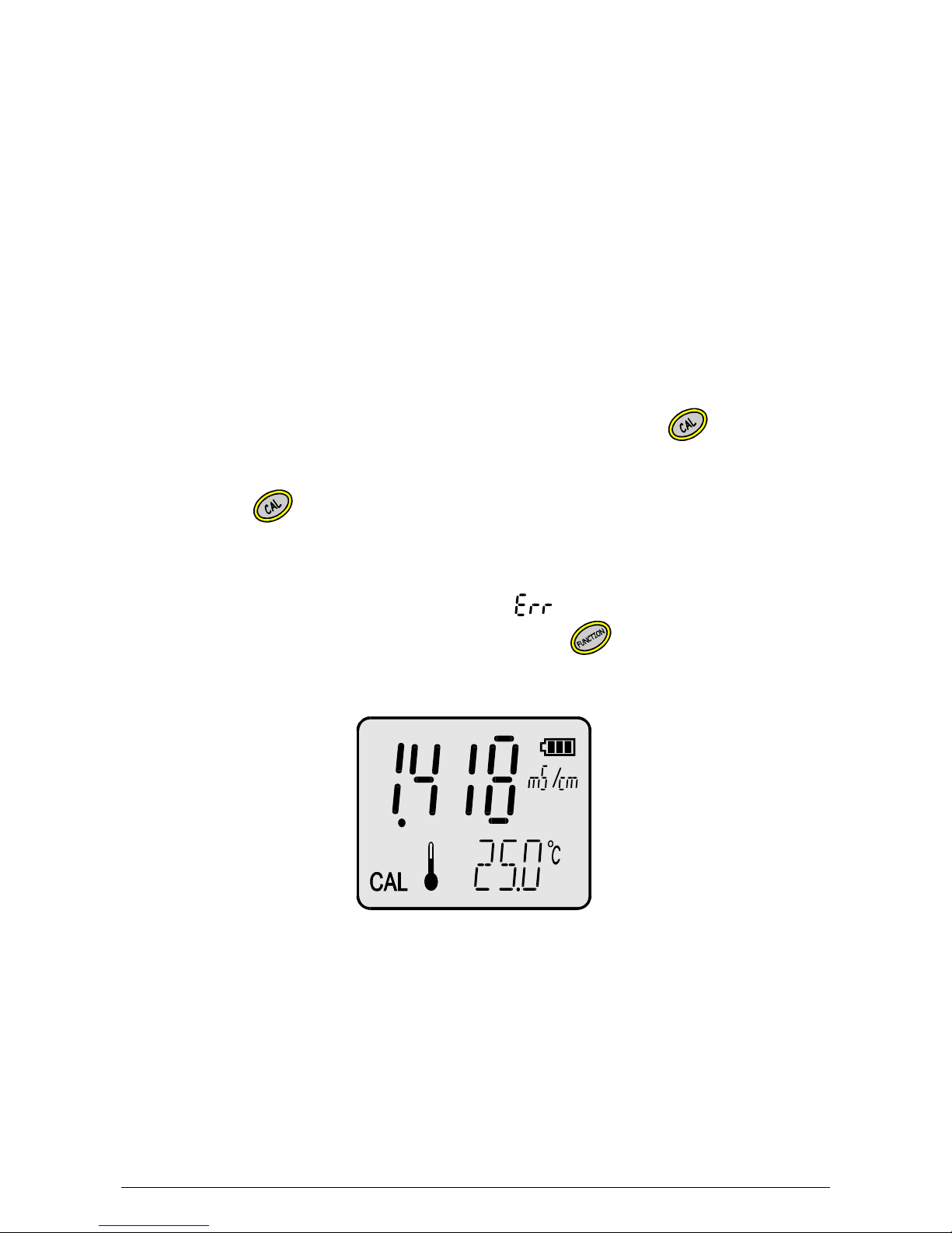
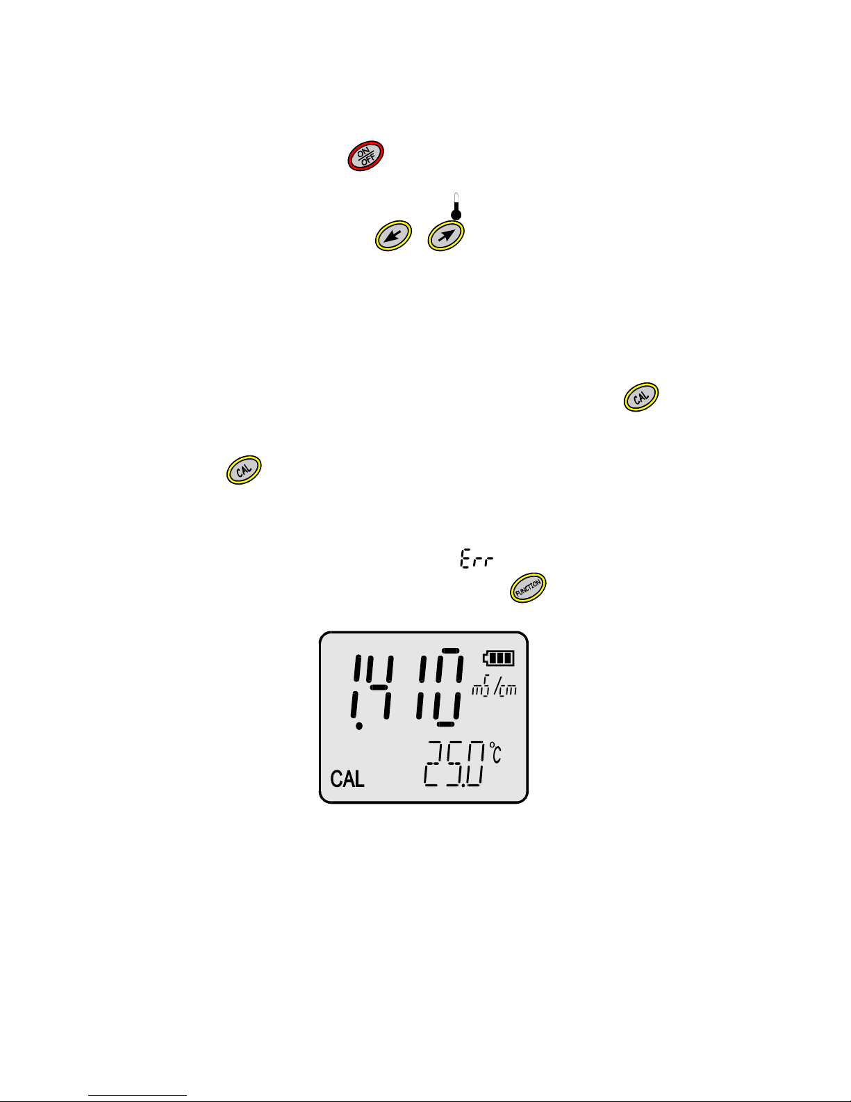
- in the conductivity measuring mode press and hold the
button till the
CAL symbol displays on the screen (Pic.9);
- after the value stabilises the P1 symbol (calibration point) will be displayed.
Press the
button. Blinking of the reading signalises recording the
calibration value, at the same time the measuremet value will be adjusted
to the applied standard value. If the applied standard value is different then
the value stored in the memory, the meter does not recognise it or the cell
connected with the meter is broken, the symbol will display.
- return to the measuring mode by pressing the button.
Pic. 9
The meter is calibrated and ready to work.
Page 27
- 21 -
9.2.3. Calibration with manual temperature compensation
In order to calibrate the meter:
- turn the meter on with the button;
- enter the standard solution value (point 9.2.1)
- disconnect the temperature probe (the symbol disappears);
- enter the 25°C value with the , buttons;
- immerse the conductivity cell in the sample solution and hold it at least 1cm
away from the bottom and the walls of the vessel. The measuring cell
should be filled with the sample solution and shouldn’t include any air
bubbles, the electrode’s surface should be evenly moistened*;
- measure the temperature of the sample solution with lab thermometer and
bring it to 25oC;
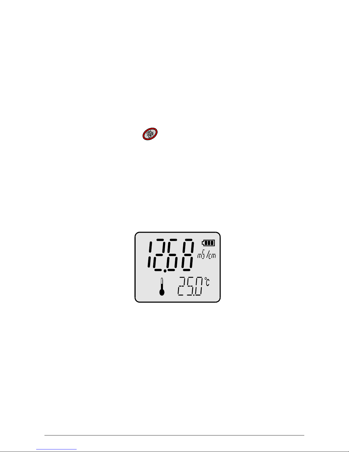
- in the conductivity measuring mode press and hold the button till
displaying the CAL symbol on the screen (Pic.10);
- after the value stabilises the P1 symbol (calibration point) will be displayed.
Press the
button. Blinking of the reading signalises recording the
calibration value, at the same time the measuremet value will be adjusted
to the applied standard value. If the applied standard value is different then
the value stored in the memory, the meter does not recognise it or the cell
connected with the meter is broken, the symbol will display;
- return to the measuring mode by pressing the button.
Pic. 10
The meter is calibrated and ready to work.
* - air bubbles may be removed by moving the immersed cell. In order to make moistening of the
electrodes easier, it is recommended to immerse the cell in distilled water with washing-up liquid, and than
wash it in distilled water.
Page 28
- 22 -
User’s manual for CC-411 conductivity meter v5.30
10. CONDUCTIVITY MEASUREMENT
10.1. Conductivity measurement without temperature compensation
Accurate conductivity measurement should be made without the temperature
compensation. The measured solution should be brought to 25 oC. It is
possible to use the temperature probe for controlling.
In order to make a measurement:
- connect the conductivity cell and the temperature probe to the connectors
F1 and t respectively (pic.2);
- turn the meter on with the button;
- choose the conductivity measuring mode according to the subchapter 6.1;
- if the conductivity cell has not been calibrated earlier calibrate it according
to the chapter 9;
- place both probes in the measured solution, the conductivity cell cannot
touch the walls and the bottom. The measuring cell should be filled with the
sample solution and should not include any air bubbles, the electrode’s
surface should be evenly moistened*;
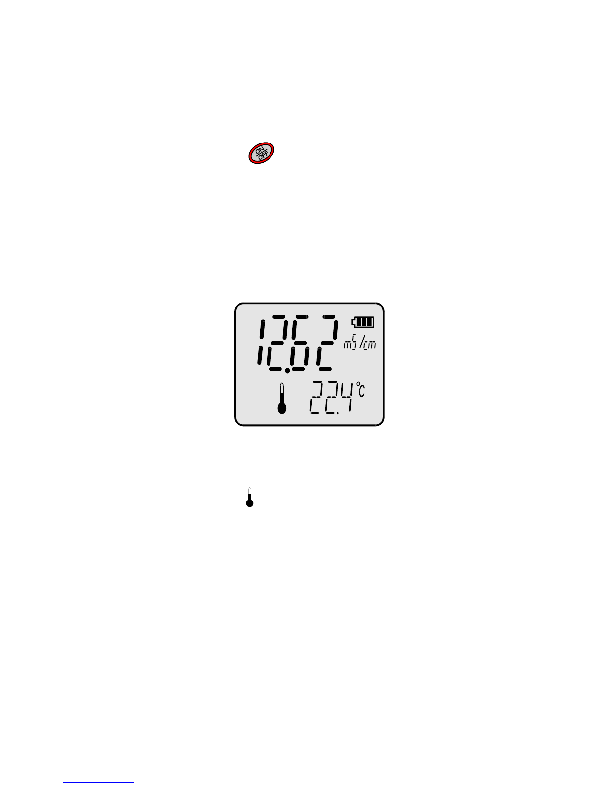
- bring the temperature of the measured solution to 25 oC;
- read the result after it has stabilised (pic.11).
Pic. 11
* - air bubbles may be removed by moving the immersed cell. In order to make moistening of the electrodes
easier, it is recommended to immerse the cell in distilled water with washing-up liquid, and than wash it in
distilled water.
Page 29
- 23 -
10.2. Conductivity measurement with automatic temperature
compensation
In case of measurement with automatic temperature compensation:
- connect the conductivity cell and the temperature probe to the connectors
F1 and t respectively (pic.2);
- turn the meter on with the
button;
- choose the conductivity measurement unit according to the subchapter 6.1;
- if the conductivity cell has not been calibrated earlier, calibrate it according
to the chapter 9;
- place both probes in the measured solution, the conductivity cell cannot
touch the walls and the bottom. The measuring cell should be filled with the
sample solution and should not include any air bubbles, the electrode’s
surface should be evenly moistened*;
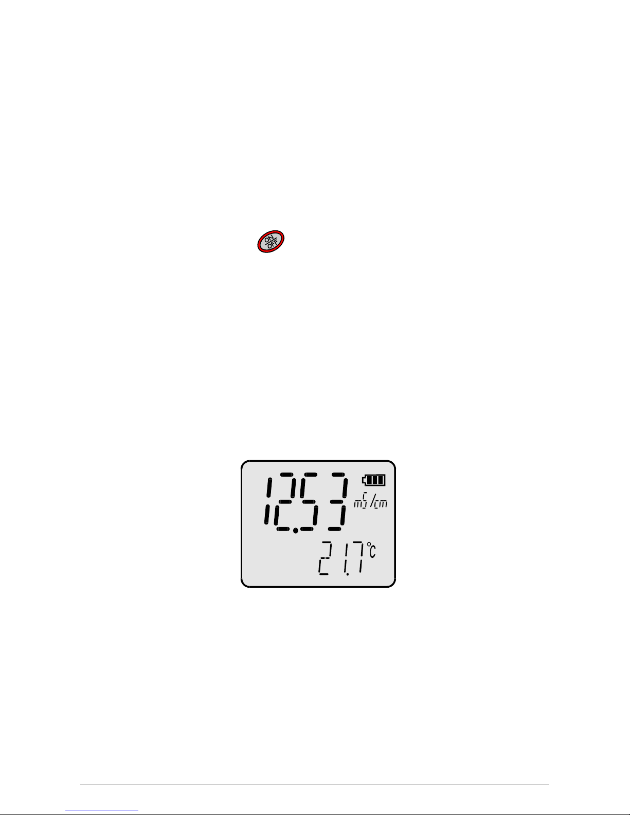
- wait till the result stabilises and read it (pic.12).
Pic. 12
Note: in case of exceeding the range of temperature compensation the
conductivity reading and the symbol start blinking
* - air bubbles may be removed by moving the immersed cell. In order to make moistening of the electrodes
easier, it is recommended to immerse the cell in distilled water with washing-up liquid, and than wash it in
distilled water.
Page 30
- 24 -
User’s manual for CC-411 conductivity meter v5.30
10.3. Conductivity measurement with manual temperature
compensation
The measurement with manual temperature compensation may be made in
stable work conditions, e.g. during measurements in laboratory, especially
with use of thermostat, or in case of the temperature probe damage.
Disconnecting the temperature probe switches the meter to manual
temperature compensation.
In case of measurement with manual temperature compensation:
- connect the conductivity cell to the F1 connector (pic.2);
- disconnect the temperature probe;
- turn the meter on with the button;
- choose the conductivity measurement unit according to the subchapter 6.1;
- if the conductivity cell has not been calibrated earlier, calibrate it according
to the chapter 9;
- measure the temperature of the solution with thermometer;
- enter the measured temperature value for manual compensation according
to the point 6.2.1 ;
- place the cell in the measured solution, it canot touch the walls and the
bottom. The measuring cell should be filled with the sample solution and
shouldn’t include any air bubbles, the electrode’s surface should be evenly
moistened*;
- after stabilisation read the result (pic.13).
Pic. 13
* - air bubbles may be removed by moving the immersed cell. In order to make moistening of the electrodes
easier, it is recommended to immerse the cell in distilled water with washing-up liquid, and than wash it in
distilled water.
Page 31
- 25 -
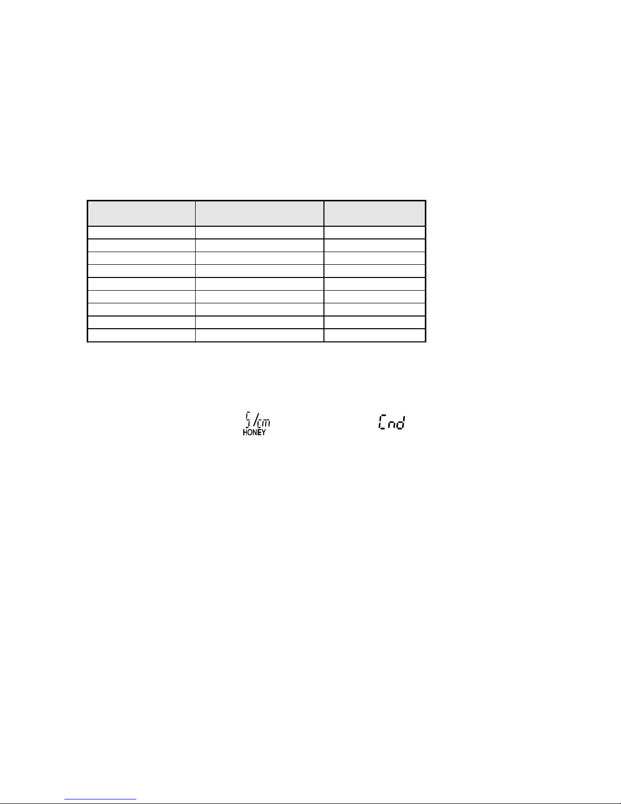
10.4. Conductivity measurement in honey
The unit of conductivity of honey given by literary sources is 10-4S/cm, which
means that one unit of conductivity of honey is equal 100 µS/cm. If the meter
indicates 250 µS/cm, it will inform about 2,5 units of honey conuctivity. If the
readout is equal 1,5 mS/cm, it will be equal 15 units of the conductivity of
honey. The table below contains conductivity values typical for different types
of honey.
Table 1.
Honey
Conductivity
x 10-4S/cm
The meter’s
indication
Fir honeydew >10 >1mS/cm
Leaf honeydew ~9 ~900 µS/cm
Honeydew-nectar ~8 ~800 µS/cm
Chestnut honey >10 >1mS/cm
Linden honey 6,8 ÷ 7,8 680 ÷ 780 µS/cm
Heath honey 2,9 ÷ 8,0 290 ÷ 800 µS/cm
Golden rod honey ~5,8 ~580 µS/cm
Buckwheat honey ~4,9 ~490 µS/cm
Borage honey ~1,27 ~127 µS/cm
10.5. Preparation of the measurement sample
Because of honey’s density, it is necessary to prepare water - honey solution
for the measurement. To do it, dilute 12g of honey in 50 ml of distilled water.
Next, choose the unit (the symbols, next to symbol, point 6.1) and
make the measurement according to the chapter 10.
Page 32
- 26 -
User’s manual for CC-411 conductivity meter v5.30
11. SALINITY MEASUREMENT
Salts and minerals dissolved in natural water influence the conductivity,
which in principle is proportional to the quantity of dissolved substances. This
dependence enables, after certain calculations, to determine the salinity of
the measured solution in concentration units (g/l or %). Received values are
always approximate and the total accuracy depends on the way of making
calculations, concentration of the measured solution and its temperature. In
most salinity meters a simplification is used, that dependence between
conductivity and salinity in the solution is linear in the whole measuring
range. Usually a 0.5 coefficient is used, the conductivity result in mS/cm is
multiplied by this coefficient and the result of salinity is received in g/l, e.g., if
the conductivity value is 2 mS/cm the salinity is 1g/l. In practice the
dependence between conductivity and salinity isn’t linear and the conversion
coefficient is changing together with the concentration and temperature.
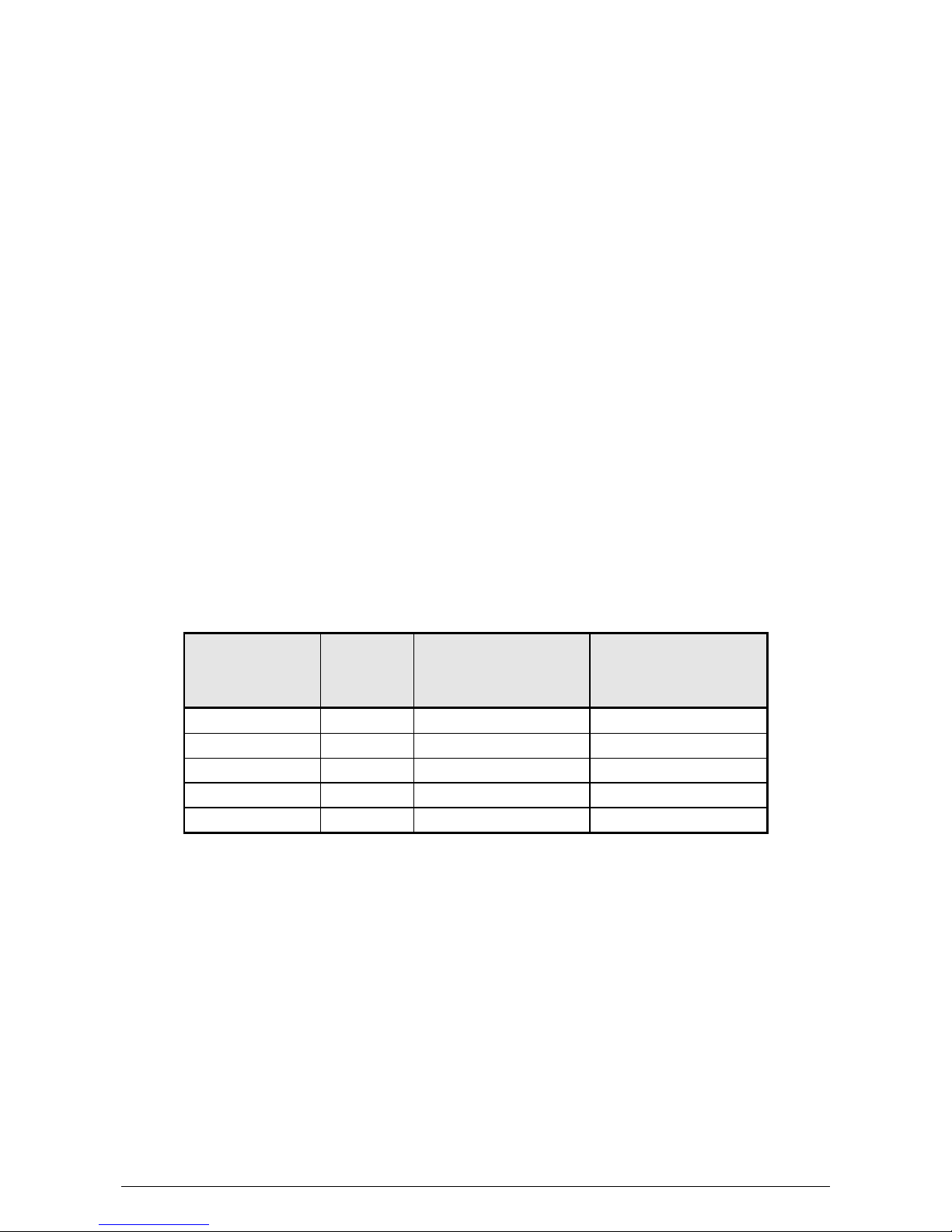
Table 1 shows the dependence between conductivity and actual salinity of
NaCl solution in temperature 25 0C and values of salinity counted for
constant coefficient 0.5. This comparison shows that using a constant
coefficient for greater concentrations introduces significant error.
Table 1.
Conductivity
(mS/cm)
Actual
salinity
(g/l)
Salinity (g/l)
Counted for
coefficient = 0.5
Error (%) by
using the
coefficient = 0.5
1.00 0.495 0.500 0.01
2.00 1.006 1.000 0.60
4.00 1.976 2.000 1.21
10.00 5.400 5.000 7.40
30.00 18.174 15.000 17.46
In CC-411 microcontroller takes into consideration the actual
dependence between the conductivity and salinity what greatly reduces
the error.
Page 33

- 27 -
11.1. Salinity measurement with conversion to NaCl
The measurement of salinity with conversion to NaCl or KCl content should
be done as follows:
- choose the salinity measurement with conversion to NaCl content
according to the chapter 6.1;
- then act as during conductivity measurement (chapter 10);
- read the result after it has stabilised.
Caution: next to the reading the unit symbol on turn with the symbol
displays.
11.2. Salinity measurement with conversion to TDS
The meter enables simplified way of determining the Total Dissolved Solids
(TDS) content. For calculations the constant coefficient is used (W
TDS
= 0.5).
The measurement of salinity with conversion to TDS should be done as
follows :
-- choose the measurement of salinity with conversion to TDS according to
the subchapter 6.1;
- act as during the conductivity measurement (chapter 10).
- after it has stabilised, read the result in g/l.
Caution: next to the reading the unit symbol on turn with the symbol
displays.
Page 34

- 28 -
User’s manual for CC-411 conductivity meter v5.30
Page 35

- 29 -
III. TEMPERATURE MEASUREMENT
Page 36

- 30 -
User’s manual for CC-411 conductivity meter v5.30
Page 37
- 31 -
12. TEMPERATURE MEASUREMENT
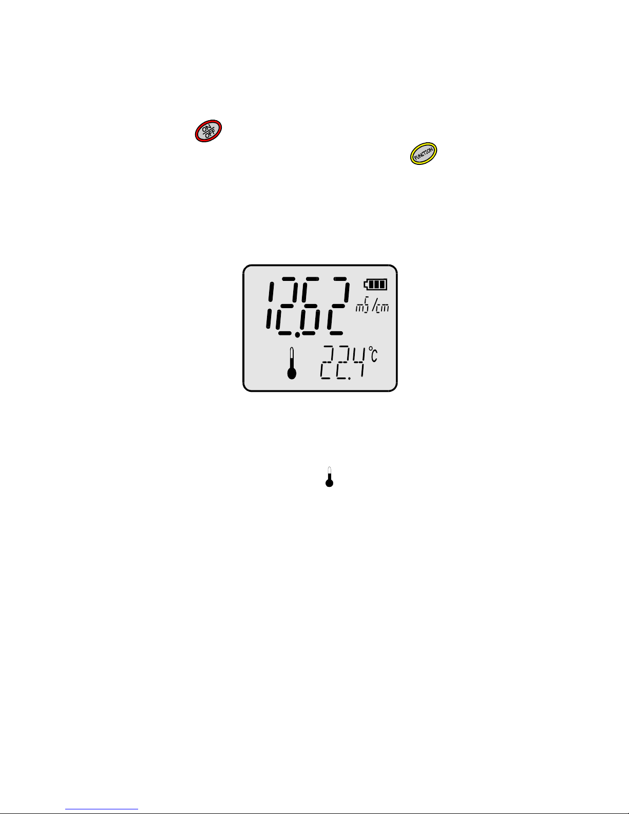
The temperature measurement is made in the following way:
- connect the temperature probe to the Chinch connector;
- by pressing the button switch the meter on;
- choose the temperature measuring mode using the button;
- put the temperature probe to the measured solution;
- wait till the value stabilises and read the result.
The meter co-operates with platinum resistor sensor PT-1000 and the final
accuracy of the temperature measurement depends on its class.
Pic. 14
NOTICE: break in the circuit or disconnecting of the temperature probe is
signalised by disappearing of the . In such case the meter shows the
temperature value introduced by the user for manual temperature
compensation. Blinking -50°C value during measurement in positive
temperatures informs about short circuit in the temperature probe.
Page 38

- 32 -
User’s manual for CC-411 conductivity meter v5.30
Page 39

- 33 -
IV. OTHER
Page 40

- 34 -
User’s manual for CC-411 conductivity meter v5.30
Page 41
- 35 -
13. READOUT OF THE SOFTWARE VERSION NUMBER
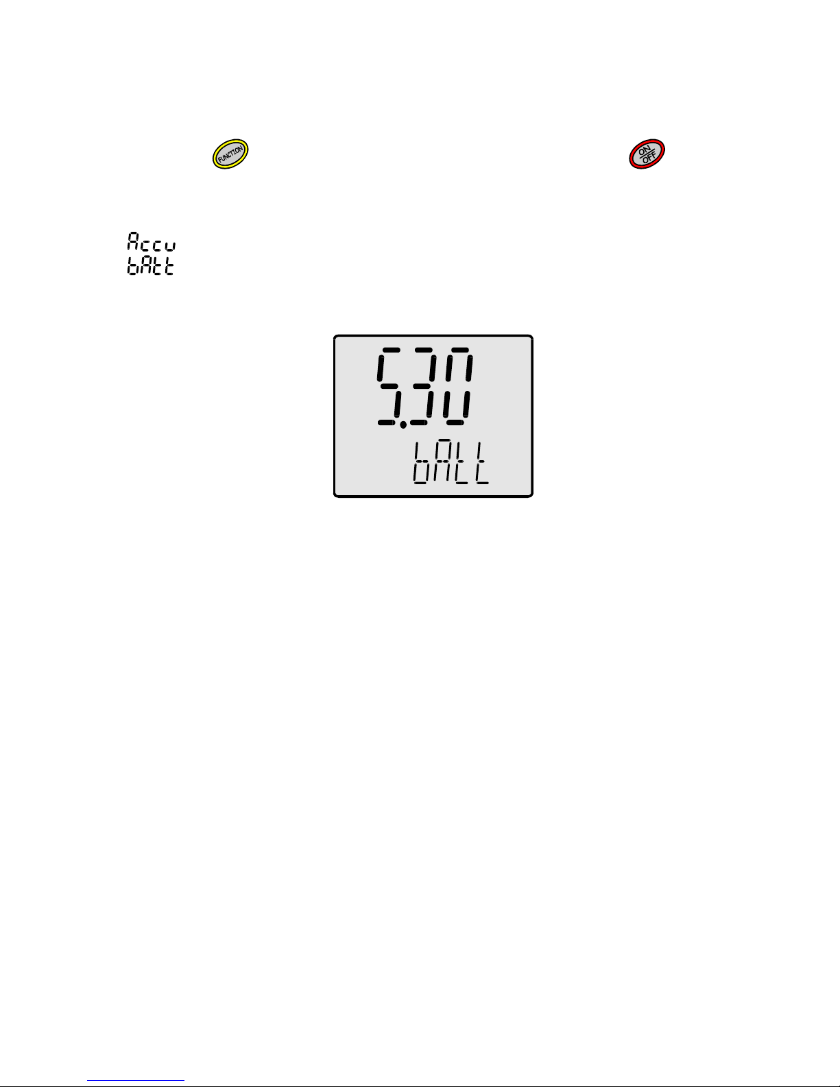
In order to check the software version number turn the meter off and next,
holding the button, turn the meter on by pressing the
button.
Instead of the display test, the screen as in the picture below will appear
(Pic. 15). In the upper row the software version will appear and in the lower
row a type of internal power supply, to which the meter has been adjusted:
- internally powered by two rechargeable R6/AA batteries;;
- internally powered by two standard R6/AA batteries.
Pic. 15
After about 1,5 s. the meter enters the measurement mode.
Page 42
- 36 -
User’s manual for CC-411 conductivity meter v5.30
14. POWER SOURCE AND CHANGING THE BATTERY
The meter is powered by 9V battery or 12V stabilised power adapter. The
adapter should be joined with the P connector (Pic.2). Connecting the power
adapter disconnects the battery and is signalised by the symbol.
The symbol informs about the battery condition. Flashing of the
symbol informs that the battery should be changed. In order to do so, it is
necessary to undo two screws in the lower wall of the meter, pull out the
whole wall and replace the battery.
The next thing is to put the new battery into the meter and mount the wall.
The wall has a sealing ring at the edge. While closing the meter, it is very
important to pay attention if the ring is put inside the housing in the whole
perimeter. Next, do the screws till the moment of resistance (not too hard).
Leaving the wall improperly screwed may cause the meter’s inundation,
which is not repaired under the warranty conditions.
Page 43
- 37 -
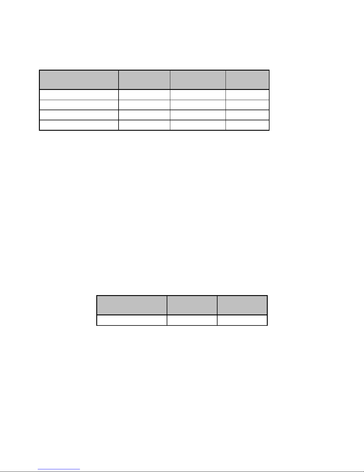
15. TECHNICAL DATA
CONDUCTIVITY MEASUREMENT:
ranges resolution
accuracy *
(±1 digit)
Frequency
0.000 ÷ 199.9 µS/cm 0.1 µS/cm
±0.25 % 1 kHz
200 ÷ 1999 µS/cm 1 µS/cm
±0.25 % 1.6 kHz
2.00 ÷ 19.99 mS/cm
0.01 mS/cm ±0.25 % 4.6 kHz
20.0 ÷ 100.0 mS/cm
0.1 mS/cm ±0.25 % 12 kHz
* Accuracy given for the upper value of the range.
Ranges of frequency changes were given for constant K = 1. For other values
of the K constant the values will change proportionally to changes of this
constant.
Temperature compensation: manual/automatic
Compensation range: -5.0 ÷ 70.0 oC
K constant range 0.05 ÷ 1.500 cm
-1
α coefficient constant 2 %/ oC
W
TDS
coefficient constant 0,5 %/ oC
Cell calibration: one-point
1. by introducing the K constant of the cell
2. with use of calibration solution
TEMPERATURE MEASUREMENT:
range resolution
accuracy*
(±1 digit)
- 50.0 ÷ 199.9 oC 0.1 oC
±0.1 oC
* accuracy of the meter. Final accuracy of the measurement depends on
the accuracy of the used PT-1000 probe
TEMPERATURE PROBE: platinum resistor Pt-1000
ACCURACY OF THE PROBE IN RANGE 0 ÷ 100 0C:
FOR PT1000B RESISTOR: ±0.8 0C
FOR PT10001/3B RESISTOR: ±0.3 0C
Page 44

- 38 -
User’s manual for CC-411 conductivity meter v5.30
OTHER:
OPERATING TEMPERATURE: -5 ÷ 45 oC
POWER: 1. 9V battery type 6F22
2. 12V power adapter
POWER CONSUMPTION: 60 mW
DISPLAY: Custom LCD 55 x 45 mm
DIMENSIONS: 149 x 82 x 22 mm
WEIGHT: 220 g
16. EQUIPMENT
Standard set:
1. Conductivity cell;
2. Pt-1000B temperature probe (standard);
3. 9V battery;
4. Plastic case for the meter, cell and temperature sensor;
5. User‘s manual with warranty.
Additional equipment:
1. 12V/100mA stabilised power adapter;
2. Pt-1000 1/3B temperature probe with higher accuracy.
Page 45

- 39 -
Page 46

- 40 -
User’s manual for CC-411 conductivity meter v5.30
Page 47

W A R R A N T Y
The “ELMETRON” company gives 24 months of warranty for the CC-411
conductivity meter number
.........................................
In case of damage the manufacturer will repair the meter within 14 days from
the day of delivery.
The warranty doesn’t cover the damages caused by usage not in conformity
with the users manual, using wrong power adapter, mechanical damages and
damages caused by repairs made by unauthorised persons.
The conductivity cell and temperature probe have 12-month manufacturer’s
warranty.
NOTICE: Before sending the meter to us for servicing please contact the firm
by phone.
Please attach the cell, temperature probe and the power adapter to the
meter.
We also provide after-warranty repair service.
Date of production...........................
Date of sale.....................................
Date of expiry..................................
Page 48

Page 49

Page 50

Page 51

Page 52

Sp. j.
41-814 Zabrze, Witosa 10, POLAND
tel. (+48) 32 2738106 fax (+48) 32 2738114
www.elmetron.com e-mail: [email protected]
 Loading...