

PSE 30
ENTFEUCHTUNGSGERÄTE
DEHUMIDIFIERS
Montage- und Betriebsanleitung
Installation and Operating Manual

2
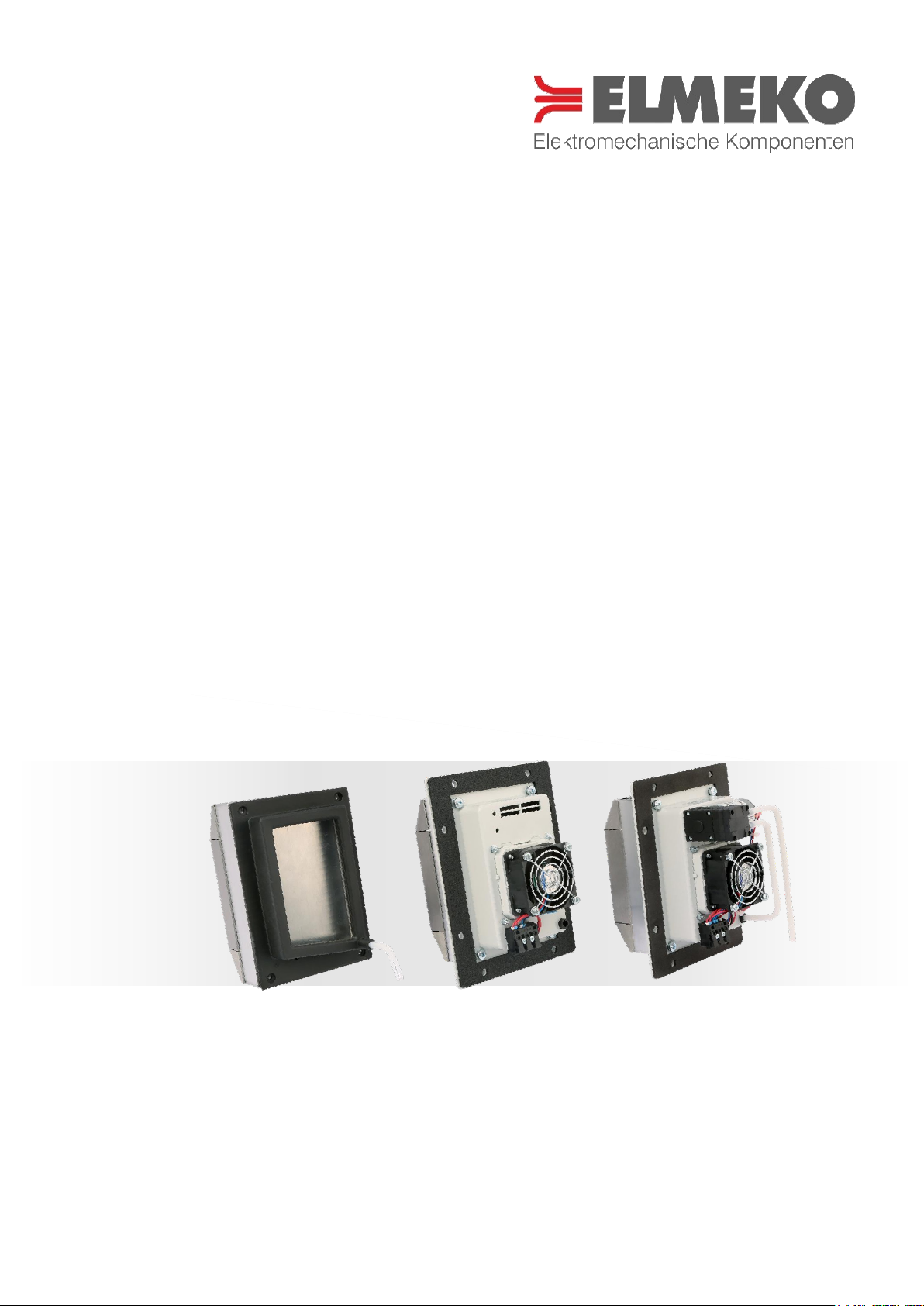
*Abbildung auf der Titelseite zeigt Entfeuchtungsgeräte in den Ausführungen Standard, L und LP
Illustration on the title page shows Dehumidifiers in the performance Standard, L and LP

3
INHALTSVERZEICHNIS TABLE OF CONTENTS
Anwendung ................................................................................................................................................................................................. 4
Technische Daten ...................................................................................................................................................................................... 4
Beschreibung .............................................................................................................................................................................................. 4
Eigenschaften ............................................................................................................................................................................................. 5
Funktion ........................................................................................................................................................................................................ 5
Lieferumfang ............................................................................................................................................................................................... 5
Zubehör ......................................................................................................................................................................................................... 5
Abmessungen ............................................................................................................................................................................................. 6
Montage ........................................................................................................................................................................................................ 7
Montageausschnitt ................................................................................................................................................................................... 8
Montageablauf PSE 30 ............................................................................................................................................................................ 9
Montageablauf PSE 30L / LP ............................................................................................................................................................... 10
Befestigungswinkel (nur PSE 30L / LP) ........................................................................................................................................... 11
Elektrischer Anschluss ........................................................................................................................................................................... 12
Anschlussbeispiel mit HYW 90 .......................................................................................................................................................... 13
Sicherheitshinweise ................................................................................................................................................................................ 14
Wartung und Pflege ............................................................................................................................................................................... 14
Garantieerklärung ................................................................................................................................................................................... 15
Application .................................................................................................................................................................................................. 4
Technical Data ............................................................................................................................................................................................ 4
Discription .................................................................................................................................................................................................... 4
Features ......................................................................................................................................................................................................... 5
Function ........................................................................................................................................................................................................ 5
Delivery contents....................................................................................................................................................................................... 5
Accessories .................................................................................................................................................................................................. 5
Dimensions PSE 30 ................................................................................................................................................................................... 6
Installation ................................................................................................................................................................................................... 7
Mounting cutout ........................................................................................................................................................................................ 8
Assembly procedure PSE 30 ................................................................................................................................................................. 9
Assembly procedure PSE 30L / LP .................................................................................................................................................... 10
Mounting bracket (only PSE 30L / LP) ............................................................................................................................................. 11
Electric installation .................................................................................................................................................................................. 12
Connection example with HYW 90 .................................................................................................................................................. 13
Safety instructions .................................................................................................................................................................................. 14
Care and maintenance .......................................................................................................................................................................... 14
Guarantee bond ....................................................................................................................................................................................... 15

4
ANWENDUNG APPLICATION
Feuchtigkeit in Schaltschränken ist ein großes Problem und wird oft unterschätzt. Bei Temperaturschwankungen
kommt es zu Kondensation und das verursacht Korrosion, Störungen und Ausfall von Steuerungen. Schon ein
Tropfen Wasser an der falschen Stelle kann erhebliche Folgen haben. Deshalb werden Entfeuchtungsgeräte über-
all eingesetzt, wo durch Feuchte oder Temperaturschwankungen Kondensation auftritt. Das ist fast generell bei
Outdooranwendungen der Fall, insbesondere bei tropischem Klima und in verschiedenen Branchen, wie z.B. der
Lebensmittelindustrie.
Moisture in switchgear cabinets is a serious problem - and one that is often underestimated. Fluctuations in temperature lead to condensation, which in turn causes corrosion, electrical faults and control unit failure. Just one
water droplet in the wrong place can have far-reaching consequences. Therefore, Dehumidifiers are installed
wherever moisture or fluctuations in temperature cause condensation. This is generally the case in almost all
outdoor applications – particularly in tropical climates – and in various specific industries e.g. the food and beverage industry.
TECHNISCHE DATEN TECHNICAL DATA
Bezeichnung Type
PSE 30
PSE 30L
PSE 30LP
Artikelnummer Part number
40 PE3 570
40 PE3 57L
40 PE3 57LP
Betriebsspannung
Operating voltage
24 V DC
24 V DC
24 V DC
Eingangs-Spannungsbereich
Input voltage range
18 - 26 V DC
18 - 26 V DC
18 - 26 V DC
Stromaufnahme
Amperage
2,2 A
2,3 A
2,6 A
Anlaufstrom
Starting current
3,4 A
3,6 A
3,6 A
Vorsicherung
Fuse
4 A (T)
4 A (T)
4 A (T)
Kühlleistung bei ∆t = 0 Kelvin
Cooling capacity at ∆t = 0 Kelvin
30 W
30 W
30 W
Nennleistung
Nominal power
47 W
50 W
56 W
Schalldruck
Sound presure
60 dB(A) @1m
64 dB(A) @1m
64 dB(A) @1m
Luftvolumenstrom
Air volume flow
-
20 m³/h
15 m³/h
Schutzart
Degree of protection
IP55 (IP65*)
IP55 (IP65*)
IP65
Lebensdauer
Service life
60.000 h
60.000 h
60.000 h
Gewicht
Weight
1200 gr.
1400 gr.
1600 gr.
Einsatztemperatur
Operating temperature
0 °C … +60 °C
0 °C … +60 °C
-0 °C … +60 °C
Zulassungen
Approval
CE CE CE
BESCHREIBUNG DISCRIPTION
Bezeichnung Type
Beschreibung und Anwendung Description and Applikation
PSE 30
Offene Kondensatwanne - senkrechte Einbauposition im stationären Betrieb (nur als Teileinbau)
Open condensate drip tray - vertical position in stationary operation (only partial internal mounting)
PSE 30L
Geschlossenes Gehäuse, mit Lüfter - senkrechte Einbauposition, möglich im mobilen Betrieb
Closed housing, with fan - vertical position, possible in mobile position
PSE 30LP
Geschlossenes Gehäuse, mit Lüfter und Kondensatpumpe - Senkrechte Einbauposition, möglich im
mobilen Betrieb und Rotation
Closed housing, with fan, with condensate pump - vertical position, possible in mobile and rotation
position
*IP65 bei Verwendung von Kondensatablaufstutzen und Fitting *IP65 when using condensate vent drain and fitting

5
EIGENSCHAFTEN FEATURES
FUNKTION FUNCTION
Entfeuchtungsgeräte arbeiten thermoelektrisch mit Peltiertechnik. Die Schaltschrankluft wird im inneren des Gerätes über eine kalte Fläche geführt, wodurch sich die Feuchtigkeit dort als Kondensat niederschlägt und gesammelt wird. Die Luft im Schrank wird dadurch getrocknet und das Kondensat wird über einen Schlauch nach unten
abgeleitet. Der Schlauch kann über die beigefügte Schottverschraubung nach außen geführt oder an einen Kon-
densatablaufstutzen aus dem Zubehör abgeschlossen werden.
Dehumidifiers operate thermoelectrically with Peltier technology. The air in the switchgear cabinet is passed over
a cold surface inside the device, resulting in precipitation of the airborne moisture as condensation. The resulting
water is then collected and drained off through a hose, leaving the air in the cabinet dry. The hose can be laid
outside via the attached bulkhead fitting or connected to a condensation drainage nozzle from the accessories.
LIEFERUMFANG DELIVERY CONTENTS
ZUBEHÖR ACCESSORIES
Bezeichnung
Type
Beschreibung Description
Artikelnummer Part number
Emparro 5
Netzteil Emparro 5
Power supply Emparro 5
42 05A 500
HYW 90
Hygrostat HYW 90
Hygrostat HYW 90
15 HYW 090
KV 60 - 24 V
Kondensatverdampfer KV 60
Condensate vaporisor KV 60
22 060 50X
AVDR4SS4
Kondensatablaufstutzen Edelstahl
Condensate vent drain stainless steel
AVDR4SS4
AVDR4NM
Kondensatablaufstutzen Kunststoff
Condensate vent drain plastic
AVDR4NM
Fitting
Fitting für Kondensatablaufstutzen
Fitting for condensate vent drain
49 FIT AVD
- Drei verschiedene Ausführungen für diverse Ein-
satzfälle
- Erhebliche Energieeinsparungen gegenüber her-
kömmlichen Heizverfahren
- Anschluss über Zugfederklemmen an 24 V DC
- Teileinbau in die Seitenwand oder Komplettein-
bau innen im Schaltschrank möglich
- Three different versions for various cases of appli-
cations
- Significant energy saving in comparison to conven-
tional heaters
- Spring cage terminals for connection to 24 V DC
- Surface mounting and semi-recessed installation in
the switchgear cabinet are possible as standard
- Entfeuchtungsgerät mit Befestigungsschrauben
- Befestigungswinkel (nur für L / LP)
- Kondensatschlauch mit 1 mtr. Länge
- Schott-Verbinder für Wanddurchführung Schlauch
- Montage- und Betriebsanleitung
- Dehumidifying device with fastening screws
- Mounting bracket (only for L / LP)
- Condensate hose, length 1 mtr.
- Bulkhead connector for feedthrough of the hose
- Installation and operating manual
6
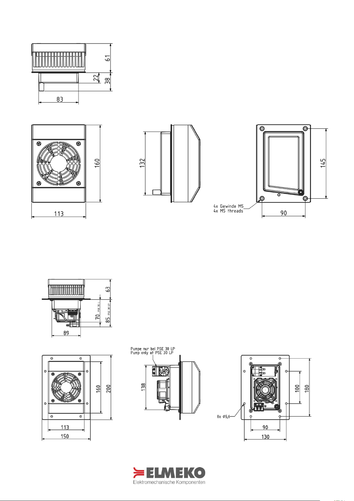
ABMESSUNGEN PSE 30 DIMENSIONS PSE 30
Alle Maße in mm All dimensions in mm
ABMESSUNGEN PSE 30L / LP DIMENSIONS PSE 30L / LP
Alle Maße in mm All dimensions in mm
7
MONTAGE INSTALLATION
Die Montage vom Entfeuchtungsgerät erfolgt entweder
- für die Geräte PSE 30 / PSE 30 L / PSE 30 LP als Teileinbau in der Schaltschrankwand – hierbei ist ein Mon-
tageausschnitt erforderlich,
- oder für die Geräte PSE 30 L / PSE 30 LP als Inneneinbau an der Schaltschrankwand bzw. Schaltschrankbo-
den – mithilfe des Montagewinkels.
Die Montageposition ist so zu wählen, dass dadurch eine Entfeuchtung des gesamten Schaltschranks möglich ist.
Das Entfeuchtungsgerät ist ein einer senkrechten Einbauposition anzubringen. Die Lufteintritts- und Luftaustritts-
öffnungen sind freizuhalten. Nur so kann sichergestellt werden, dass die maximale Reduzierung der Luftfeuchte
erreicht wird. Für welche Montagemöglichkeit Sie sich entscheiden, hängt letztlich vom Platzbedarf innerhalb
und außerhalb des Schaltschranks ab und hat keinen Einfluss auf die abzuführende Luftfeuchtigkeit. Lediglich ein
leichter Anstieg der Innentemperatur ist möglich.
The dehumidifier is installed either
- for the devices PSE 30 / PSE 30 L / PSE 30 LP as a partial mounting in the enclosure wall – this requires a
mounting cutout,
- or for the devices PSE 30 L / PSE 30 LP as an internal installation on the enclosure wall or floor – using the
mounting bracket.
The mounting position should be selected so that dehumidification of the entire enclosure is possible. The dehumidifier must be installed in a vertical position. The air inlet and air outlet openings are to be kept unhindered.
Only in this way can it be ensured that the maximum reduction in air humidity is available. Which mounting option you choose depends ultimately on the space requirement inside and outside of the enclosure and has no
influence on the airborne moisture. Only a slight increase in the internal temperature is possible.
Teileinbau Partial internal mounting
Für die Montage als Teileinbau ist ein Ausschnitt in Türe, Seitenwand oder Rück-
wand des Gehäuses erforderlich. Der Montageausschnitt muss der senkrechten
Montageposition entsprechend sein, mit dem Kondensatablauf nach unten. Das
PSE 30 Standard ist ausschließlich für Teileinbau geeignet.
For installation a cutout is necessary which can be done in door, side or rear of
the enclosure. The mounting cutout must be according to the vertical mounting
position, with condensate drainage downwards. The device PSE 30 standard is
only suitable for partial internal mounting.
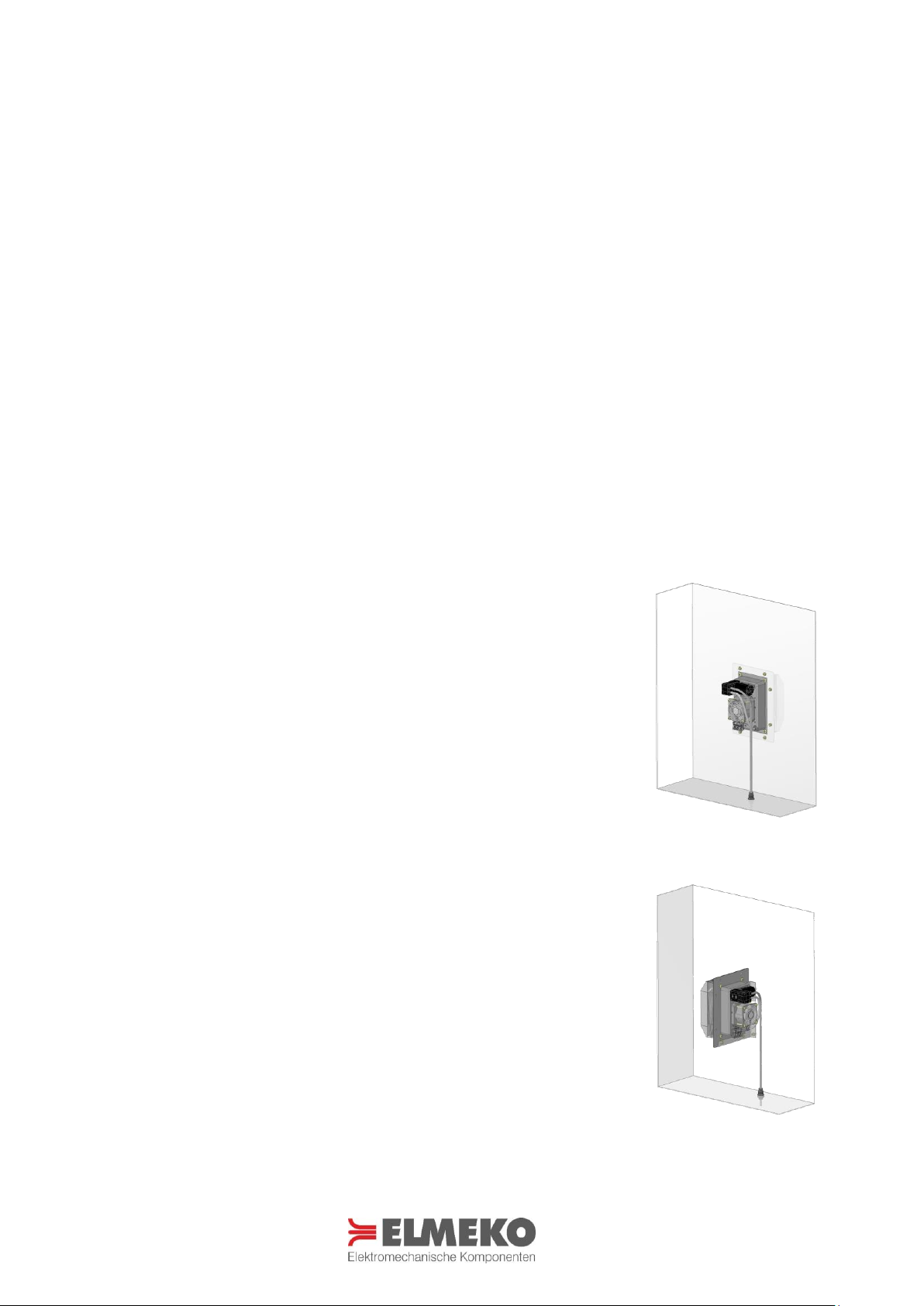
Inneneinbau Internal mounting
Für die Montage im Innenbereich des Schaltschranks benötigt es lediglich zwei
Bohrungen um den bereits im Lieferumfang enthaltenen Befestigungswinkel an
der Seitenwand oder am Schaltschrankboden zu befestigen. Das Lochbild für
den Befestigungswinkel muss der senkrechten Montageposition entsprechend
sein, mit dem Kondensatablauf nach unten.
For installation in the interior of the control cabinet, it only requires two holes to
attach the mounting bracket already included in the delivery on the side wall or
on the cabinet floor. The hole pattern for the mounting bracket must be in accordance with the vertical mounting position, with condensate drainage downwards.

8
MONTAGEAUSSCHNITT PSE 30 MOUNTING CUTOUT PSE 30
Alle Maße in mm All dimensions in mm
MONTAGEAUSSCHNITT PSE 30L / LP MOUNTING CUTOUT PSE 30L / LP
Alle Maße in mm All dimensions in mm
Mit dem QR-Code haben Sie direkten Zugang zur
Homepage www.elmeko.de wo der Montageausschnitt als PDF oder DXF Datei heruntergeladen
werden kann
With the QR code you have direct access to the
homepage www.elmeko.de where the mounting
cutout can be downloaded as PDF or DXF file
Mit dem QR-Code haben Sie direkten Zugang zur
Homepage www.elmeko.de wo der Montageausschnitt als PDF oder DXF Datei heruntergeladen
werden kann
With the QR code you have direct access to the
homepage www.elmeko.de where the mounting
cutout can be downloaded as PDF or DXF file
9
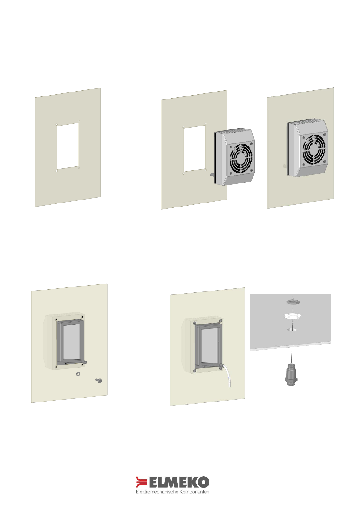
MONTAGEABLAUF PSE 30 ASSEMBLY PROCEDURE PSE 30
Die horizontale Einbauposition (Kondensatablaufstutzen nach unten) ist unbedingt einzuhalten. Der Konden-
satschlauch muss in einen Behälter unterhalb des Gerätes oder durch die Schaltschrankwand nach außen geführt
werden.
The horizontal installation position (condensate drain downwards) must be observed. The condensate hose must
be led into a container underneath the device or outwards through the enclosure wall.
Senkrechten Montageausschnitt mit
Bohrungen nach Zeichnung anfertigen
Make vertical mounting cutout and
drill holes according to drawing
Das Entfeuchtungsgerät in den Ausschnitt einsetzen, so dass der
Kühlkörper mit Lüfter und Anschlussklemme in den Schaltschrank
hineinragen, mit dem Kondensatablauf nach unten.
Put the device into the cutout so that the heatsink with fans and terminals protrude into the enclosure, with condensate drainage downwards.
Ansicht von innen: das Entfeuchtungsgerät mit vier Linsenkopfschrauben
M5x16 mit Unterlegscheibe befestigen
(5 Nm)
View from inside: fasten the device
with four head screws M5x16 with
washers (5 Nm)
Kondensatschlauch einsetzen und mittels der Schottverschrau-
bung durch den Boden oder die Schaltschrankwand nach außen
führen. Beim Einbau vom Dichtring pressen sich die vorstehen-
den Lippen in die Gewindegänge.
Insert the condensate hose and guide it outwards through the
bottom or the cabinet wall using the bulkhead connection.
When installing the sealing ring press the retaining lips in the
threads.

10
MONTAGEABLAUF PSE 30L / LP ASSEMBLY PROCEDURE PSE 30L / LP
Die horizontale Einbauposition (Kondensatablaufstutzen nach unten) ist unbedingt einzuhalten. Bei rotierendem
Betrieb muss sichergestellt werden, dass das Kondensat durch die Drehbewegung in Richtung des Ablaufs fließt.
Der Kondensatschlauch muss in einen Behälter unterhalb des Gerätes oder durch die Schaltschrankwand nach
außen geführt werden.
The horizontal installation position (condensate drain downwards) must be observed. For rotating application
must be ensured that the condensate flows through the rotary movement in the direction of the drain. The condensate hose must be led into a container underneath the device or outwards through the enclosure wall.
Senkrechten Montageausschnitt mit
Bohrungen nach Zeichnung anfertigen
Make vertical mounting cutout and
drill holes according to drawing
Das Entfeuchtungsgerät in den Ausschnitt einsetzen, so dass der
Kühlkörper mit Lüfter und Anschlussklemme in den Schaltschrank
hineinragen, mit dem Kondensatablauf nach unten.
Linsenkopfschrauben M5x16 einsetzen.
Put the device into the cutout so that the heatsink with fans and
terminals protrude into the enclosure, with condensate drainage
downwards. Insert head screw M5x16.
Ansicht von innen: das Entfeuchtungsgerät mit
acht selbstsichernden Muttern M6 mit Unterlegscheiben befestigen (7 Nm)
View from inside: fasten the device with eight selflocking nuts M6 with washers (7 Nm)
Kondensatschlauch einsetzen und mittels der
Schottverschraubung durch den Boden oder die
Schaltschrankwand nach außen führen. Beim Einbau vom Dichtring pressen sich die vorstehenden
Lippen in die Gewindegänge.
Insert the condensate hose and guide it outwards
through the bottom or the cabinet wall using the
bulkhead connection. When installing the sealing
ring press the retaining lips in the threads.
11
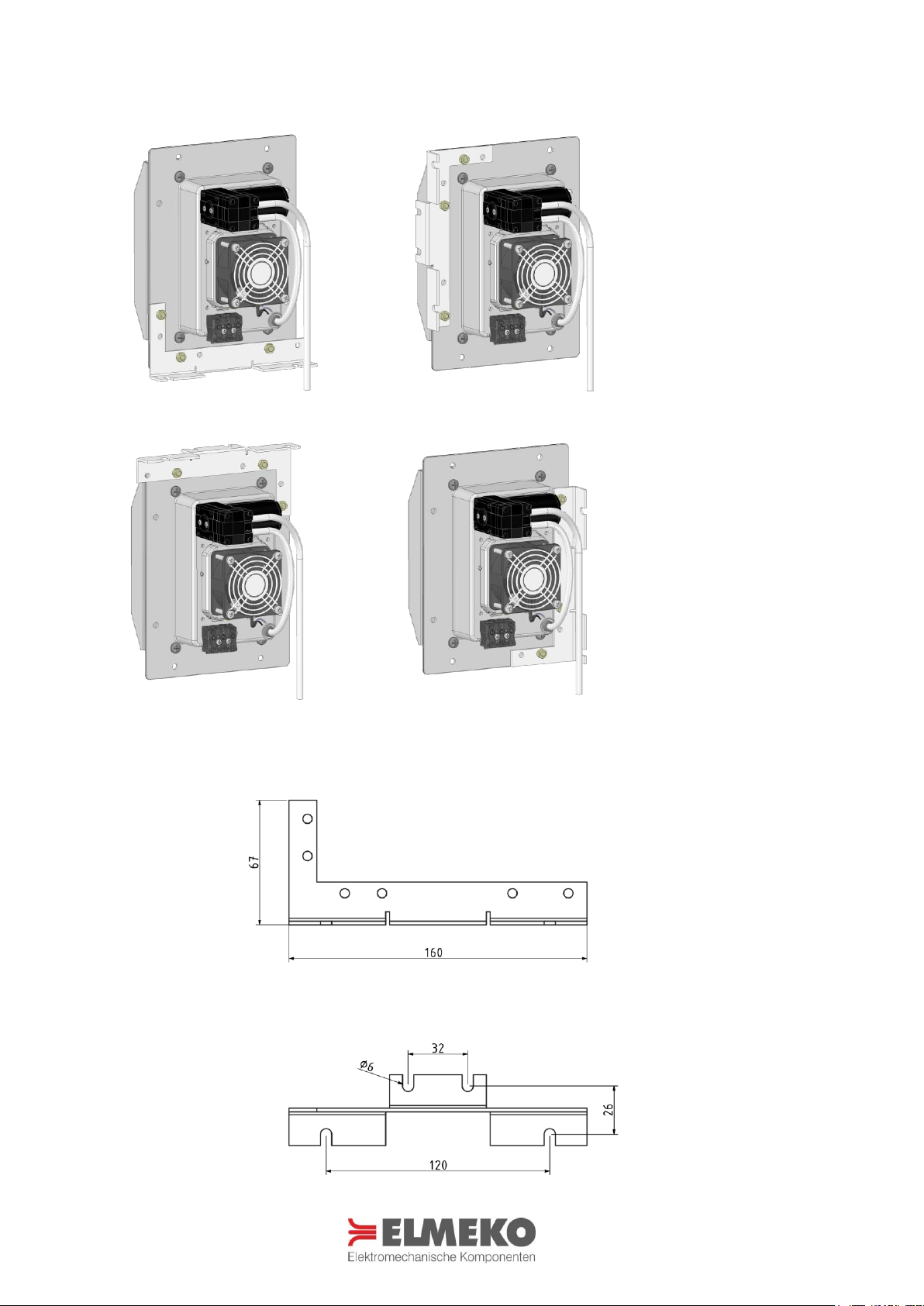
BEFESTIGUNGSWINKEL (NUR PSE 30L / LP) MOUNTING BRACKET (ONLY PSE 30L / LP)
Lochbild Befestigungswinkel Hole pattern mounting bracket

12
ELEKTRISCHER ANSCHLUSS ELECTRIC INSTALLATION
Für den elektrischen Anschluss ist der Schaltschrank vorher vorschriftsmäßig außer Betrieb zu nehmen. Die Spannungsversorgung ist an die Anschlussklemmen bzw. Leitung anzuschließen. Es wird eine Gleichstromspannung
von 24 V DC benötigt. Achtung: Bei Anschluss an Wechselspannung wird das Gerät zerstört.
For the electrical connection, the control cabinet must first be disconnected. Connect the supply voltage to the
terminal or connection cable. The power supply requires an DC voltage of 24 V DC. ATTENTION: AC current will
destroy the cooler.
Schaltbild PSE 30 Wiring diagram PSE 30
Schaltbild PSE 30L Wiring diagram PSE 30L
Schaltbild PSE 30LP Wiring diagram PSE 30LP
Aufgrund der geringen Kondensatmenge sollte die Pumpe nicht dauernd laufen, sondern erst nach dem Abschalten der Entfeuchtung für 30-60 Sekunden eingeschaltet werden.
Due to the small condensate volume the pump should not run continuously. It should be switched on for 30-60
seconds after switching off of the dehumidifying device.
Bezeichnung
Term
Belegung Connection
1+
24 V DC Entfeuchtung (rot)
24 V DC Dehumidification (red)
2-
0V DC (schwarz)
0V DC (black)
Bezeichnung
Term
Belegung Connection
1+
24 V DC Entfeuchtung
24 V DC Dehumidification
2-
0V DC
0V DC
(3+)
Frei
Free
Bezeichnung
Term
Belegung Connection
1+
24 V DC Entfeuchtung
24 V DC Dehumidification
2-
0V DC
0V DC
3+
24 V DC Pumpe
24 V DC Pump

13
ANSCHLUSSBEISPIEL MIT HYW 90* CONNECTION EXAMPLE WITH HYW 90*
PSE 30 PSE 30 PSE 30L PSE 30L
PSE 30 LP PSE 30LP
* Hygrostat und Netzteil sind Zubehör und müssen separat bestellt werden
Hygrostat and power supply are accessories and must be ordered separately

14
SICHERHEITSHINWEISE SAFETY INSTRUCTIONS
- Die Installation darf nur von autorisiertem Fachpersonal vorgenommen werden. Die landesüblichen
Richtlinien sind gemäß IEC 60364 einzuhalten
- Die technischen Daten auf dem Typenschild und in dieser Anleitung sind zu beachten
- Der Anschluss erfolgt an 24 V DC
- Anschlusskabel sind nur als Kupferleitungen zulässig
- Die maximale Umgebungstemperatur von bis zu 60 °C ist zu berücksichtigen
- Die Umgebung des Geräts darf max. Verschmutzungsgrad 2 entsprechen
- Vorschriften des EVU sind zu beachten
- Bei Beschädigung des Gehäuses oder der Anschlussleitung Spannung abschalten und alle Stecker abziehen
- Achtung! Beim Öffnen des Gerätes erlischt die Garantie
- Schutzmaßnahmen nach VDE 0100 sind sicherzustellen
- Bei der Herstellung von Montageausschnitten und Bohrungen ist geeignete Schutzausrüstung zu tragen
- Luftein- und Luftaustrittsöffnungen des Gerätes dürfen nicht abgedeckt werden
- Stellen Sie vor der Montage sicher, dass der Schaltschrank dicht verschlossen ist, ansonsten tritt später wäh-
rend des Betriebs eine erhöhte Kondensatbildung auf
- Bei niedrigen Umgebungstemperaturen kann es zu Eisbildung im inneren des Gerätes kommen. Vor dem Ab-
pumpen muss dann das Auftauen des Kondensats abgewartet werden
- Installation must only be carried out by qualified electrical technicians in observation of the respective national
power supply guidelines (IEC 60364)
- The technical specifications on the identification plate and in this manual, must be observed
- Supply voltage is 24 V DC
- Connection cables only as copper conductors only
- Taking into account the maximum surrounding air temperature rating of 60 °C
- The environment of the device may be maximum with pollution degree 2
- If the housing, or wire is damaged, switch off the voltage supply and disconnect all plugs
- Attention! Opening the case will void guarantee
- The safety measures according to VD 0100 have to be ensured
- Wear protective gear when cutting the mounting cut out and drilling the fastening holes
- The air inlet and outlet openings to the unit must not be covered
- Before mounting, make sure that the enclosure is tightly closed, otherwise condensation will occur later during
operation
- At low ambient temperatures it can come to ice formation inside the device. Before evacuating must be waited
for defrosting of the condensate
WARTUNG UND PFLEGE CARE AND MAINTENANCE
- Das Entfeuchtungsgerät ist wartungsarm.
- Führen Sie in regelmäßigen Abständen eine Sichtprüfung an den Lüftern und dem Aussenkühlkörper durch.
- In staubbelasteter Umgebung kann ein Ausblasen des Kühlkörpers mit Druckluft zur Erhaltung der Leistung
erforderlich sein. Dabei muss das Gerät spannungsfrei geschaltet werden!
- The thermoelectric cooler is low-maintenance
- Regularly perform a visual inspection at the fans and the outer heatsink.
- Dusty environments may require a cleaning of the heatsink with compressed air to maintain the performance.
Before cleaning disconnect the device from the mains!
Die Entsorgung muss gemäß den jeweiligen nationalen gesetzlichen Bestimmungen erfolgen.
The disposal is to occur according to the respective national regulations.
WEEE-Reg.-Nr.: DE 78723147

15
GARANTIEERKLÄRUNG GUARANTEE BOND
Wir gewähren eine Garantiezeit von 24 Monaten ab dem Zeitpunkt der Lieferung des Gerätes bei bestimmungsgemäßen Einsatz und unter den folgenden Betriebsbedingungen:
- Einsatz in Schaltschränken oder Gehäusen für industrielle Anwendungen
- Beachtung der auf dem Typenschild angegebenen Anschlussspannung und Anschlussleistung
Diese Garantie gilt nicht für evtl. Schäden, die dem Gerät zugefügt werden durch:
- Inbetriebnahme in ungeeigneter Umgebung, z. B. in saurer oder ätzender Atmosphäre
- Anschluss an eine andere Spannung, wie auf dem Typenschild angegeben
- Überspannung, z. B. Blitzeinschlag
- Äußere Gewaltanwendung
Die Garantie entfällt bei einer Benutzung, die nicht den Vorschriften in der Betriebsanleitung entspricht.
Im Schadensfall innerhalb der Garantiezeit übernimmt der Hersteller eine Materialgarantie, indem die fehlerhaften Bauteile repariert oder ersetzt werden. Der Hersteller übernimmt keinerlei Verantwortung außerhalb der Reparatur oder dem Austausch defekter Bauteile. Der Hersteller übernimmt keine Aufwendungen für Aus- und Ein-
bau des Gerätes, oder der Folgeschäden. Die reparierten oder ausgetauschten Bauteile verändern den Beginn
oder die Beendigung der Garantiezeit in keiner Weise.
Es liegt in der Verantwortung des Kunden, die richtige Erdung, Installation und Stromversorgung des Gerätes
entsprechend der gültigen Vorschriften sicherzustellen.
Achtung: Alle Eingriffe in das Gerät haben den Verfall der Gewährleistung und den Haftungsausschluss zur Folge!
We grant a guarantee of 24 months starting from delivery and when the operating instructions are fully complied with and when they are used in the following conditions:
- Operation in enclosures or cabinets for industrial applications
- Power supply must be same as indicated on the identification plate
This guarantee does not cover any damage to the product due to:
- Using the product in unsuitable environment, e.g. in acid or corrosive atmospheres
- Connection to a supply voltage different from that indicated on the identification plate
- Electrical overload, e.g. through lightning strike
- Damage caused by external force
The guarantee is void with a use, which does not correspond to the regulations in the operating manual.
For each component found to be faulty during the term of the guarantee, the manufacturer will, according to its
unquestionable judgement, repair, and/or substitute the faulty components free of charge. The manufacturer is
in no way held liable except for repairing or substituting faulty products. The manufacturer is not responsible for
any additional expenses incurred for removing, handling and installation if required. The repaired or replaced
products do not change the time the guarantee starts or ends.
It is the customer’s responsibility to see to the correct protective earth connection, installation, and power supply
of the product in compliance with current standards.
Attention: Tampering with the product in any way will void the warranty and exclude any liability!

16
Rev. 10/2019
ELMEKO GmbH + Co. KG Graf-Zeppelin-Str. 5 56479 Liebenscheid Germany
Tel. +49/2736/509748-0 info@elmeko.de www.elmeko.de
 Loading...