

ELMEKO LLE-400-S, LLE-700-S, LLE-400-B, LLE-700-B, LLE-400-BM Installation And Operating Manual
...
LLE-400/700-S/B
LED SCHALTSCHRANKLEUCHTE
LED ENCLOSURE LIGHT
Montage- und Betriebsanleitung
Installation and Operating Manual

2
INHALTSVERZEICHNIS TABLE OF CONTENTS
Beschreibung ................................................................................................................................................................................................. 3
Anwendung .................................................................................................................................................................................................... 3
Abmessungen ............................................................................................................................................................................................... 3
Technische Daten ........................................................................................................................................................................................ 4
Schaltbild LLE-400/700-B ......................................................................................................................................................................... 5
Schaltbild LLE-400/700-S ......................................................................................................................................................................... 5
Zubehör ........................................................................................................................................................................................................... 6
Montage .......................................................................................................................................................................................................... 6
Sicherheitshinweise .................................................................................................................................................................................... 7
Garantieerklärung........................................................................................................................................................................................ 8
Description ..................................................................................................................................................................................................... 3
Application ..................................................................................................................................................................................................... 3
Dimensions .................................................................................................................................................................................................... 3
Technical Data .............................................................................................................................................................................................. 4
Wiring diagram LLE-400/700B ............................................................................................................................................................... 5
Wiring diagram LLE-400/700-S ............................................................................................................................................................. 5
Accesories ....................................................................................................................................................................................................... 6
Installation ...................................................................................................................................................................................................... 6
Safety instructions ....................................................................................................................................................................................... 7
Guarantee bond ........................................................................................................................................................................................... 8

3
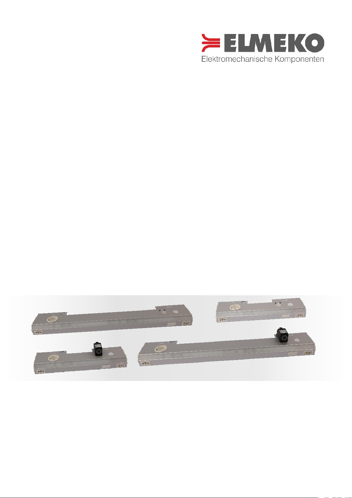
BESCHREIBUNG DESCRIPTION
Die LLE-Serie wurde speziell für den Einsatz in Schaltschränken entwickelt. Besondere Merkmale sind das stabile
Aluminiumgehäuse, der schräge Lichtaustritt über die gesamte Länge der Leuchte, steckbare Anschlüsse und
verschiedene Schaltmöglichkeiten. Außer mit dem eingebauten Türpositionsschalter oder Bewegungsmelder kann
die Leuchte auch von extern geschaltet werden. Die Einschaltdauer des Bewegungsmelders beträgt ca. 5 Minuten
(nur LLE-400/700-B).
The LLE series was specially developed for use in switchgear cabinets. Its distinguished features are a sturdy
aluminium enclosure, the slanted light emission over the entire length of the light, plug-in connectors and various
switching possibilities. Besides the fitted door position switch or motion detector, the light can also be switched
on externally. The switch-on duration off the motion detector is approximately 5 minutes (only LLE-400/700B).
ANWENDUNG APPLICATION
Die LLE-Leuchten dienen zur Ausleuchtung des Innenraums von Schaltschränken und Gehäusen.
Über den eingebauten Türpositionsschalter oder Bewegungsmelder wird die Leuchte beim Öffnen der Türe
eingeschaltet. Die eingebaute Schuko Steckdose dient zum Anschluss von Messgeräten im Servicefall. Die
steckbare Verbindung für die Zuleitung und die Verbindung von weiteren Leuchten vereinfachen die Installation.
Bei der Verbindung von mehreren Leuchten darf die Belastung von allen Steckdosen nicht höher als 16 A sein.
LLE lights are used to illuminate the interior of enclosures and housings.
When the doors are opened, the light can be switched on via the attached door position switch or motion
detector. The built-in socket may be used for power supply of measuring instruments in case of service.
The installation is made easier by the plug-in connectors for power supply and connection to additional lights.
When several lights are connected, the load all outlets should be together no more than 16 A.
ABMESSUNGEN DIMENSIONS
Alle Maße in mm All dimensions in mm
Bezeichnung
Type
A B C
LLE-400
403
250
120
LLE-700
703
550
420

4
TECHNISCHE DATEN TECHNICAL DATA
Bezeichnung Type
LLE-400-S
LLE-400-B
LLE-700-S
LLE-700-B
Artikelnummer Part number
72 400 15S
72 400 15B
72 700 15S
72 700 15B
Betriebsspannung
Operating voltage
230 V AC
230 V AC
230 V AC
230 V AC
Leistungsaufnahme
Power input
10 W
10 W
20 W
20 W
Stromaufnahme
Amperage
50 mA
50 mA
100 mA
100 mA
Lichtleistung
Luminosity
660 lm
660 lm
1300 lm
1300 lm
Beleuchtungsstärke
Illumination
630 lx@0,5m
210 lx@1m
630 lx@0,5m
210 lx@1m
800 lx@0,5m
250 lx@1m
800 lx@0,5m
250 lx@1m
Farbtemperatur
Color temperature
6.000 K
6.000 K
6.000 K
6.000 K
Schutzart
Degree of protection
IP20
IP20
IP20
IP20
Schutzklasse
Protection type
I I I
I
Lebensdauer [Std. bei 20 °C]
Service life [h at 20 °C]
60.000 h
60.000 h
60.000 h
60.000 h
Gehäusematerial
Housing material
Aluminium
Aluminum
Aluminium
Aluminum
Aluminium
Aluminum
Aluminium
Aluminum
Gewicht
Weight
1100 gr.
1000 gr.
1700 gr.
1600 gr.
Max. Luftfeuchtigkeit [% rF]
Max. humidity [% rH]
90 %
90 %
90 %
90 %
Einsatztemperatur [ °C]
Operating temperature [°C]
-20 °C … +60 °C
-20 °C … +60 °C
-20 °C … +60 °C
-20 °C … +60 °C
Umgebungstemperatur (Lager)
Ambient temperature (storage)
-40 °C … +85 °C
-40 °C … +85 °C
-40 °C … +85 °C
-40 °C … +85 °C
Zulassungen
Approval
CE CE CE CE

5
SCHALTBILD LLE-400/700-B WIRING DIAGRAM LLE-400/700B
SCHALTBILD LLE-400/700-S WIRING DIAGRAM LLE-400/700-S

6
LIEFERUMFANG DELIVERY CONTENTS
ZUBEHÖR ACCESORIES
Bezeichnung
Type
Beschreibung Description
Artikelnummer Part number
LL-N-30
Netzanschlusskabel 3 mtr. lang, orange, einseitig mit
GST-Stecker
Mains cable 3 mtr. long, orange, GST plug at one side
72 30N 000
LL-V-06
Verbindungskabel 0,6 mtr. zum Durchschleifen von
weiteren Leuchten, beidseitig mit GST-Stecker
Connection cable 0,6 mtr. for daisy chain connection, GST
plugs at both sides
72 06V 000
LL-V-10
Verbindungskabel 1,0 mtr. zum Durchschleifen von
weiteren Leuchten, beidseitig mit GST-Stecker
Connection cable 1,0 mtr. for daisy chain connection, GST
plugs at both sides
72 10V 000
MONTAGE INSTALLATION
Die Leuchte wird oben oder seitlich am Rahmen des Schaltschranks mit zwei Schrauben befestigt.
Der elektrische Anschluss erfolgt über einen dreipoligen Stecker an der Frontseite an 230 V AC 50/60 Hz. Dazu
sind fertige Anschlusskabel als Zubehör erhältlich. Über einen weiteren dreipoligen Einbaustecker können weitere
Leuchten angeschlossen werden.
The light is fixed to the frame with two screws at the top or side of the enclosure.
The electrical connection is made via a three-pin connector on the front to 230 V AC 50/60 Hz. Prefabricated
cables are available as accessories. Another three-pole female connector is available to connect further lights.
Einbau der Leuchte von unten
Mounting of the light from below
- LED-Leuchte
- Befestigungsschrauben
- LED light
- Fastening screws

7
SICHERHEITSHINWEISE SAFETY INSTRUCTIONS
- Die Installation darf nur von autorisiertem Fachpersonal vorgenommen werden. Die landesüblichen
Richtlinien sind gemäß IEC 60364 einzuhalten
- Die technischen Daten auf dem Typenschild und in dieser Anleitung sind zu beachten
- Der Anschluss erfolgt an 230 V AC 50/60 Hz
- Die maximale Vorsicherung ist 16 A
- Vorschriften des EVU sind zu beachten
- Die eingebaute Steckdose ist bis maximal 16 A belastbar. Bei Verbindung von mehreren Leuchten darf
die Belastung von allen Steckdosen nicht höher als 16 A sein
- Die Leuchte darf nur in Schaltschränken oder Gehäusen eingesetzt und betrieben werden
- Nicht in die Leuchte blicken! Das Sehvermögen kann dadurch beeinträchtigt werden
- Bei Beschädigung des Gehäuses oder der Anschlussleitung Spannung abschalten und alle Stecker abziehen
- Bei defektem Taster oder defekten LED’s muss die Leuchte zum Hersteller zurückgeschickt werden
- Achtung! Beim Öffnen des Gehäuses erlischt die Garantie
- Schutzmaßnahmen nach VDE 0100 sind sicherzustellen
- Die Leuchte muss ortsfest angebracht werden
- Die Leuchte niemals als Handleuchte verwenden
- Installation must only be carried out by qualified electrical technicians in observation of the respective
national power supply guidelines (IEC 60364)
- The technical specifications on the identification plate and in this manual, must be observed
- Supply voltage is 230 V AC 50/60 Hz
- The maximum back-up fuse is 16 A
- The built-in socket is loadable up to 16 A. When several lights are connected, the load of all outlets should
be together no more than 16 A
- The light may only be used and operated in cabinets or enclosures
- Do not look into the light! Eyesight can be impaired
- If the housing or wire is damaged, switch off the voltage supply and disconnect all plugs
- When the switch or LEDs are defective, the light must be sent back to the manufacturer
- Attention! Opening the light will void guarantee
- The safety measures according to VD 0100 have to be ensured
- The light must be installed stationary
- Never use the light as hand lamp
Die Entsorgung muss gemäß den jeweiligen nationalen gesetzlichen Bestimmungen erfolgen.
The disposal is to occur according to the respective national regulations.
WARNUNG
Bei Missachtung der Anschlusswerte
besteht die Gefahr von Personen- und
Geräteschädigung.
WARNING
There is a risk of personal injury and
equipment damage if the connection
values are not observed.

8
GARANTIEERKLÄRUNG GUARANTEE BOND
Wir gewähren eine Garantiezeit von 24 Monaten ab dem Zeitpunkt der Lieferung des Gerätes bei
bestimmungsgemäßen Einsatz und unter den folgenden Betriebsbedingungen:
- Einsatz in Schaltschränken oder Gehäusen für industrielle Anwendungen
- Beachtung der auf dem Typenschild angegebenen Anschlussspannung und Anschlussleistung
Diese Garantie gilt nicht für evtl. Schäden, die dem Gerät zugefügt werden durch:
- Inbetriebnahme in ungeeigneter Umgebung, z. B. in saurer oder ätzender Atmosphäre
- Anschluss an eine andere Spannung, wie auf dem Typenschild angegeben
- Überspannung, z. B. Blitzeinschlag
- Äußere Gewaltanwendung
Die Garantie entfällt bei einer Benutzung, die nicht den Vorschriften in der Betriebsanleitung entspricht.
Im Schadensfall innerhalb der Garantiezeit übernimmt der Hersteller eine Materialgarantie, indem die fehlerhaften
Bauteile repariert oder ersetzt werden. Der Hersteller übernimmt keinerlei Verantwortung außerhalb der Reparatur
oder dem Austausch defekter Bauteile. Der Hersteller übernimmt keine Aufwendungen für Aus- und Einbau des
Gerätes, oder der Folgeschäden. Die reparierten oder ausgetauschten Bauteile verändern den Beginn oder die
Beendigung der Garantiezeit in keiner Weise.
Es liegt in der Verantwortung des Kunden, die richtige Erdung, Installation und Stromversorgung des Gerätes
entsprechend der gültigen Vorschriften sicherzustellen.
Achtung: Alle Eingriffe in das Gerät haben den Verfall der Gewährleistung und den Haftungsausschluss zur Folge!
We grant a guarantee of 24 months starting from delivery and when the operating instructions are fully complied
with and when they are used in the following conditions:
- Operation in enclosures or cabinets for industrial applications
- Power supply must be same as indicated on the identification plate
This guarantee does not cover any damage to the product due to:
- Using the product in unsuitable environment, e.g. in acid or corrosive atmospheres
- Connection to a supply voltage different from that indicated on the identification plate
- Electrical overload, e.g. through lightning strike
- Damage caused by external force
The guarantee is void with a use, which does not correspond to the regulations in the operating manual.
For each component found to be faulty during the term of the guarantee, the manufacturer will, according to its
unquestionable judgement, repair, and/or substitute the faulty components free of charge. The manufacturer is in
no way held liable except for repairing or substituting faulty products. The manufacturer is not responsible for any
additional expenses incurred for removing, handling and installation if required. The repaired or replaced
products do not change the time the guarantee starts or ends.
It is the customer’s responsibility to see to the correct protective earth connection, installation, and power supply
of the product in compliance with current standards.
Attention: Tampering with the product in any way will void the warranty and exclude any liability!
ELMEKO GmbH + Co. KG Graf-Zeppelin-Str. 5 56479 Liebenscheid Germany
Tel. +49/2736/509748-0 info@elmeko.de www.elmeko.de
Rev. 01/2018
 Loading...