

Page 1
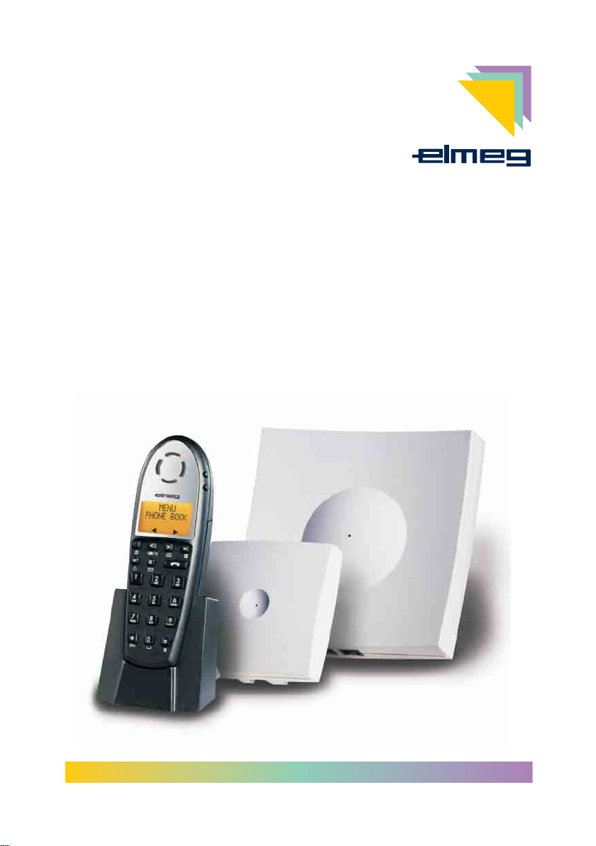
Installation elmeg DECT 300
Page 2

Inhaltsverzeichnis
Systembeschreibung . . . . . . . . . . . . . . . . . . . . . . . . . . . . . . . 1
Positionierung einer Basisstation oder eines Repeaters . . . . . . . . . . . . . 1
Intendend Use . . . . . . . . . . . . . . . . . . . . . . . . . . . . . . . . . . 1
Sicherheitshinweise. . . . . . . . . . . . . . . . . . . . . . . . . . . . . . . . 2
Lieferumfang . . . . . . . . . . . . . . . . . . . . . . . . . . . . . . . . . . . 2
Montage der Basisstation. . . . . . . . . . . . . . . . . . . . . . . . . . . . . 2
Anschlüsse der Basisstation . . . . . . . . . . . . . . . . . . . . . . . . . . . 4
Bedeutung der LED in der Basisstation . . . . . . . . . . . . . . . . . . . . . 5
Repeater . . . . . . . . . . . . . . . . . . . . . . . . . . . . . . . . . . . . . 5
Einbuchen der Repeater . . . . . . . . . . . . . . . . . . . . . . . . . . . . . . 6
Anmerkung zum Repeater: . . . . . . . . . . . . . . . . . . . . . . . . . . . . 6
Programmier-Tools . . . . . . . . . . . . . . . . . . . . . . . . . . . . . . . . 6
Garantieleistungen . . . . . . . . . . . . . . . . . . . . . . . . . . . . . . . . 7
Contents
Description of the System . . . . . . . . . . . . . . . . . . . . . . . . . . . . 1
Positioning of a Base Station or Repeater . . . . . . . . . . . . . . . . . . . . 1
Intendend Use . . . . . . . . . . . . . . . . . . . . . . . . . . . . . . . . . . 1
Safety notes. . . . . . . . . . . . . . . . . . . . . . . . . . . . . . . . . . . . 2
Contents of package . . . . . . . . . . . . . . . . . . . . . . . . . . . . . . . 2
Installing the Base Station . . . . . . . . . . . . . . . . . . . . . . . . . . . . 2
Base Station Terminals . . . . . . . . . . . . . . . . . . . . . . . . . . . . . . 4
Significance of the Base Station LED. . . . . . . . . . . . . . . . . . . . . . . 5
Repeater . . . . . . . . . . . . . . . . . . . . . . . . . . . . . . . . . . . . . 5
Enrolling (Logging on) repeaters . . . . . . . . . . . . . . . . . . . . . . . . . . 6
Note concerning repeater: . . . . . . . . . . . . . . . . . . . . . . . . . . . . 6
Programming Tools . . . . . . . . . . . . . . . . . . . . . . . . . . . . . . . . 6
Warranty . . . . . . . . . . . . . . . . . . . . . . . . . . . . . . . . . . . . . 7
Page 3

Systembeschreibung
Das elmeg DECT300 System ist eine DECT Basisstation mit integriertem Controller für
den Betrieb von max. 8 »elmeg DECT handsets«. Die Basisstation wird über Installa
tionskabel an eineelmegTK-Anlage mit biszu8 analogen Anschlüssenangeschlossen.
Jedem eingebuchten Mobilteil wird ein analoger Anschluss fest zugeordnet. Werden an
der Basisstation 8Mobilteileeingebucht, muss dieBasisstation auch mit8analogen An
schlüssen andie TK-Anlageangeschlossen werden. Die analogen Eingänge der Basis
station sind galvanisch von der Telefonanlage getrennt.
Die Anzeige der Rufnummer des Anrufers (CLIP) ist nur mit elmeg TK-Anlagen möglich,
Hierzu muss eine serielle Verbindung (RS232 / V.24) zwischen der TK-Anlage und der
Basisstation installiert werden.Für diese Verbindungkönnen Sie das »elmeg DECTV.24
CLIP-Kabelset« oder das Programmierkabel der Basisstation nutzen.
-
-
-
Die Entfernung zwischen der Basisstation und der TK-Anlage sollte für die Übertra
gung CLIP-Informationen nicht mehr als 50 Meter betragen.
Der Funkbereich der Basisstation kann durch den Einsatz von max. 6 »elmeg DECT re
peatern« erweitert werden, wobei max. 3 Repeater in einer Reihe angeordnet werden
können. Jeder Repeater erweitert den Funkbereich wiederumum 25-300m, wobei Berücksichtigt werden muss, dass sich die Funkbereiche “überlappen” müssen.
Die Basisstation liefert sechs simultaneSprachkanäle (gleichzeitige Gespräche),ein Repeater lediglich zwei. Repeater dienenlediglich derErweiterung des Funkbereiches und
nicht der Erweiterungum Sprechkanäle. Wirdim Bereich desRepeater ein Kanal belegt,
wird ebenfalls in der Basisstation ein Kanal belegt.
Das System darf nur an internen analogen Anschlüssen von TK-Anlagen angeschlossen werden. Alle Einstellungen der Basisstation sind für den analogen Anschluss an elmegTK-Anlagen vorbereitet (Z.B. Flash Zeit, a/bAnpassungen, usw.).
Veränderungen oder Anpassungen sind nicht notwendig.
Nutzen Sie an einem elmeg DECT300 Systemnur »elmeg DECT handsets«, da die
Funktion anderer Mobilteile nicht sicher gestellt ist.
Positionierung einer Basisstation oder eines Repeaters
Der DECT Sende-/ Empfangsbereich breitet sich kreisförmig um die Basisstation aus
und beträgt im Radius ca. 25 – 300 m. Die Funkausbreitung ist stark abhängig von den
Umgebungsbedingungen. Z. B. schränken mit Stahl bewehrte Beton-Wände und De
cken die Ausbreitung erheblich ein, während Leichtbau- oder auch Steinwände die
DECT Funkstrahlung leichter durchlassen. Für eine optimale Funkausbreitung ist die
Basisstation so zu positionieren, dass möglichst viele Räume im Bereich der Funkab
deckung liegen. Bevor die Basisstation fest montiert wird, sollte der bestmögliche
Standort ermittelt werden. Hierfür kann durch ein Gespräch zwischen zwei Mobilteilen
der Empfang an verschiedenen Standorten überprüft werden.
-
-
-
-
Intendend Use
Das elmeg DECT 300 ist ein schnurloses mehrzelliges DECT-System zur analogen An
schaltung an elmeg TK-Anlagen mit CLIP-Funktion.
1
-
Page 4

Sicherheitshinweise
Umgebungstemperatur für die Lagerung: -25°C ... +70°C.
•
Umgebungstemperatur für den Betrieb: +5°C ... +40°C.
•
Die Basisstation darf erst nach Erreichen der zulässigen Betriebs-Umge
bungstemperatur angeschlossen werden.
Beachten Sie bitte, dass beim Übergang von kalten zu warmen Temperaturen kei
ne Betauung am oder im Gerät entstehen darf.
Entnehmen Sie die Basisstation erst aus der Verpackung, wenn die zulässige Be
triebs-Umgebungstemperatur erreicht ist.
Vermeiden Sie die folgenden Einflüsse:
•
Direkte Sonneneinstrahlung
Wärmequellen (z.B. Heizkörper)
Elektronische Geräte (z.B. HiFi-Geräte, Bürogeräte oder Mikrowellenge
räte)
Eindringende Feuchtigkeit oder Flüssigkeiten
Reinigen Sie die Basisstation nur mit einem leicht angefeuchteten Tuch.
•
Verwenden Sie nur das zugelassene Zubehör.
•
Es ist möglich, dass in bestimmten Fällen medizinische Geräte durch ein-
•
geschaltete DECT-Geräte beeinflusstwerden können. Bittebeachten Sie
daher die Bestimmungen der entsprechenden örtlichen Gegebenheiten.
Während eines Gewitters sollten Sie keine Leitungen anschließen, tren-
•
nen oder telefonieren.
•
Ziehen Sie das Steckernetzgerät, bevor Sie den Gehäusedeckel entfernen und Arbeiten am Anschlussklemmenfeldvornehmen. SetzenSie den
Gehäusedeckel wieder auf, bevor Sie das Steckernetzgerät wieder stecken.
-
-
-
-
Lieferumfang
•
Basis
•
Steckernetzteil (2430)
•
Schrauben / Dübel
•
Kunststoffschelle (Zugentlastung)
•
Installationsanleitung
Montage der Basisstation
•
Beachten Sie die Sicherheitshinweise.
•
Suchen Sie einen Montageort aus, der max. 1,5 Meter von einer 230V~
Netzsteckdose entfernt ist und eine gute Funkausbreitung bietet.
Öffnen Sie das Gehäuse nur im spannungslosem Zustand.
Achtung! Sie könnten elektrostatisch Aufgeladen sein. Bevor Sie die Basisstation
öffnen, müssen Sie sich durch Berühren eines leitenden mit »Erde« verbundenen
Gegenstandes (z.B. Wasserleitung) entladen.
2
Page 5
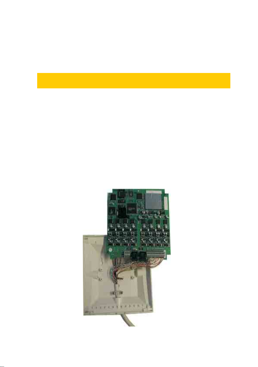
Öffnen Sie die Basisstation.
•
Betätigen Sie unterleichtem Druckdie 4 Rasthakenauf der Rückseite der
Basisstation. Nach Abnahme der Oberschale wird die Platine der Basis
sichtbar.
Lösen Sie die Befestigungsschrauben der Platine und heben diese he
•
raus. Die Unterschale kann jetztan der Wand befestigt werden. Verwen
den Sie hierzu die mitgelieferten Dübel und Schrauben.
Die Basisstation darf nur mit den Anschlüssen nach unten (siehe Bild 1) montiert
werden, da sonst keine optimale Funkabdeckung gegeben ist.
Führen Sie das Installationskabel durch die Unterseite in das Gehäuse
•
ein. Hierzu brechen Sie bitte den vorgestanzten Verschluss aus. Zur Fi
xierung (Zugentlastung) des Installationskabels wird der beiliegende
Kunststoffschelle, wie in Bild 1 dargestellt, festgeschraubt.
Schließen Sie das Installationskabel der analogen Anschlüsse an der
•
16poligen Klemmleiste an (siehe »Anschlüsse der Basisstation«).
Schrauben Sie die Platine wieder an der Unterseite des Gehäuses fest.
•
Achten Siedarauf, dass die Adern des Installationskabel nicht verklemmt
werden.
Setzten Sie nun die Oberschale wieder auf. Unter leichtem Druck rasten
•
die Rasthaken ein.
Stecken Sie den Westernstecker des Steckernetzgerätes in die Buchse
•
(siehe Bild 1). Verwenden Sie ausschließlich das in der Verpackung der
Basisstation mitgelieferte Steckernetzteil mit der Nummer 2430.
• Stecken Sie das Steckernetzgerät in die 230V~ Netzsteckdose.
-
-
-
Bild 1
3
Page 6
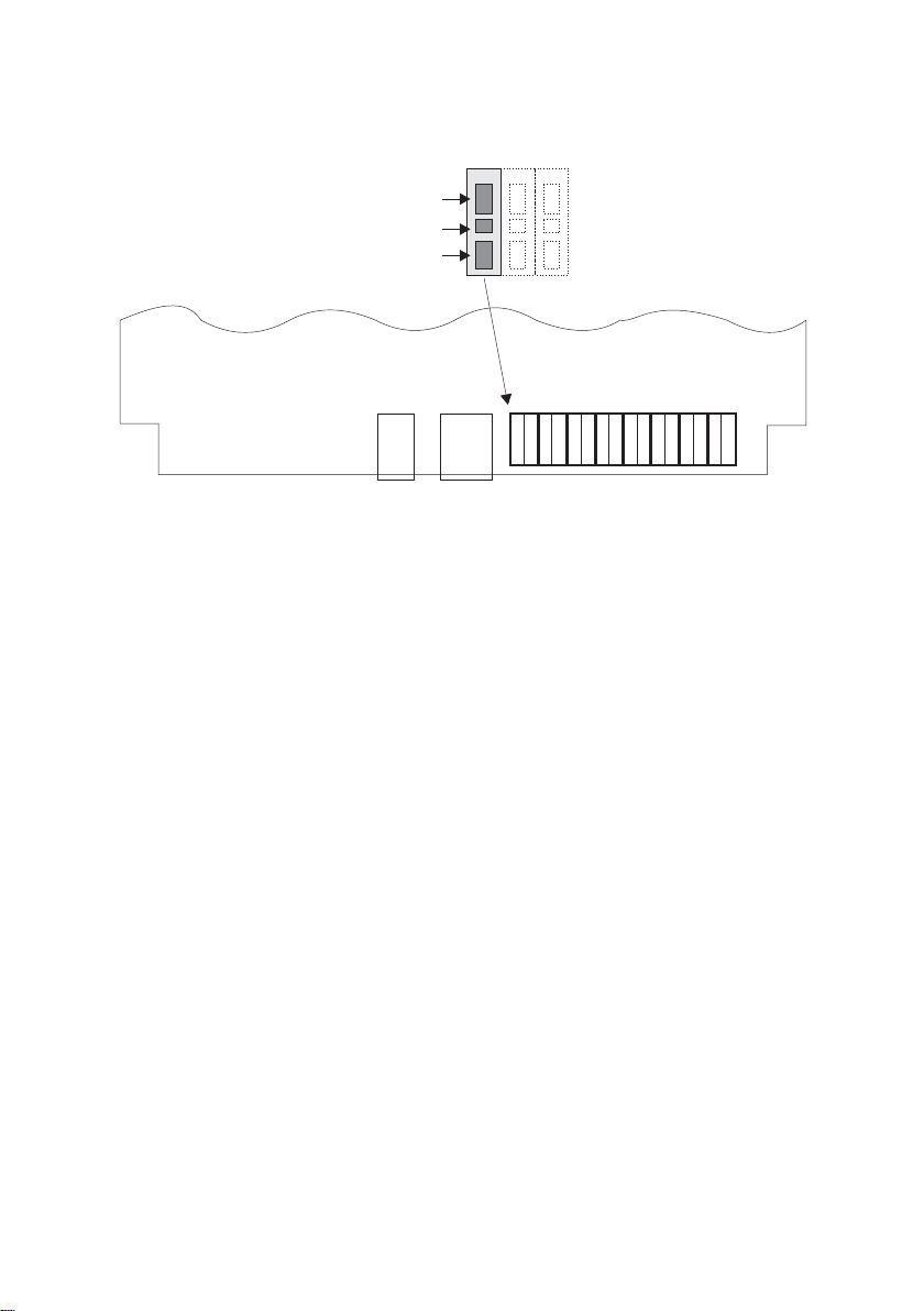
Anschlüsse der Basisstation
K1
K2
K3
Line 7
Line 6
Line 5
Line 4
Line 3
Line 2
Line 1
Line 0
a
b
a
b
a
a
a
b
b
b
12 3
Bild 2
1 Anschluss für Steckernetzgerät(Nummer 2430)
2 seriellerAnschluss (RS232 / V.24)der Basisstation für dieProgrammierungderBa-
sisstation über Software-Tools oder Verbindung zur elmeg-TK-Anlage für die Rufnummernübermittlung (CLIP)
3 16polige Klemmleiste für8 analoge Anschlüsse (Anschluss0 rechts nebenderse-
riellen Schnittstelle)
Die einzelnen Adern des Installationskabels werden an den Klemmen (K3) angeschlossen. Drückenhierzu Sie die Kontaktfedern (K1oder K2) mit einem passenden Schraubendreher herunter und stecken Sie die ca. 7 mm abisolierten Adern
des Installationskabels inden Klemmblock. PrüfenSie bitte denkorrektenHalt der
Drähte durch vorsichtigen Zug.
a
a
a
b
b
b
Beachten Sie bittediefeste Zuordnung vonMobilteilenzu den analogenAnschlüssen:
Mobilteil eingebucht auf Kanal 0 (Masterhandset) Anschluss (Line) 0
Mobilteil eingebucht auf Kanal 1 Anschluss (Line) 1
Mobilteil eingebucht auf Kanal 2 Anschluss (Line) 2
Mobilteil eingebucht auf Kanal 3 Anschluss (Line) 3
Mobilteil eingebucht auf Kanal 4 Anschluss (Line) 4
Mobilteil eingebucht auf Kanal 5 Anschluss (Line) 5
Mobilteil eingebucht auf Kanal 6 Anschluss (Line) 6
Mobilteil eingebucht auf Kanal 7 Anschluss (Line) 7
4
Page 7

Anmerkung zum Masterhandset:
Werden die Mobilteile wie in der Bedienanleitung beschrieben eingebucht, erhält das
Masterhandset als erstes Mobilteil im System die feste Zuordnung zum Kanal 0.
Das elmeg DECT300 System kann jedoch auch mit einem SW-Programm (Program
mierkabel erforderlich) eingerichtetwerden.Über diese Softwarekann das Masterhand
set auch auf anderen Kanälen eingebucht werden.
Bedeutung der LED in der Basisstation
Rote LED
Leuchtet ständig: Fehler oder Programmiermodus.
Leuchtet langsam blinkend: Normalbetrieb, alle Gesprächskanäle belegt.
Leuchtet schnell blinkend: System ist nicht konfiguriert. Anmeldung von Mobilteilen
nicht möglich.
Grüne LED
Leuchtet ständig: Normalbetrieb, keine Gesprächskanäle belegt.
Langsam blinkend: Normalbetrieb, ein –oder mehrere Gesprächskanälesind
belegt.
Leuchtet schnell blinkend: System nicht konfiguriert. Anmeldung von Mobilteilen ist
möglich.
-
-
Repeater
Der »elmeg DECT repeater« erweitert die DECT Funkabdeckung um den Bereich von
25-300 m (Abhängigvonden Umgebungsbedingungen). DerRepeaterstellt gleichzeitig
zwei Gesprächskanäle zur Verfügung. Da diese Kanäle lediglich von der Basis “gelie
hen” sind, dient der Repeater also der Erweiterung der abgedeckten Fläche und nicht
der Erweiterung mit Funkkanälen.
Der Repeater wird drahtlos an der Basis angemeldet und muss daher im Funkbereich
der Basis positioniert werden. Durch ein Steckernetzteil wird der Repeater an eine
230V~ Netzsteckdose angeschlossen. Für die Positionierung des Repeaters beachten
Sie bitte die Hinweise auf Seite 1 dieser Montageanleitung.
Den imLieferumfang des Repeaters enthaltenen Kunststoffwinkel montieren Sie ander
Wand, verbinden das Steckernetzteil und setzten den Repeater in den Halter ein.
Rote LED
Leuchtet ständig: Der Repeater ist an einer Basis angemeldet
(Normalbetrieb),
Leuchtet langsam blinkend: Der Repeater sucht eine Basisstation(Auslieferzustand).
5
-
Page 8

Leuchtet schnell blinkend: Der Repeater befindet sich im Programmier- oder
Einbuchmodus.
Einbuchen der Repeater
Für das EinbuchendesRepeater, muss dieserinden Einbuchmodus gebrachtwerden:
Verbinden Sie den Repeater mind. 1 sec. – max. 5 sec. mit dem Strom
•
netz.
Innerhalb dieser Zeit wieder vom Netz trennen und erneut einstecken
•
Die LED des Repeaters blinkt jetzt langsam. Es wird eine Basis gesucht.
•
Dieser Modus ist für 5 Minuten aktiv.
Wird eine Basis gefunden, blinkt die LED schnell.
•
Um sicherzustellen, dass es sich um die richtige Basis handelt (falls sich
•
mehr DECT Basen in der Umgebung befinden), betätigen Sie die Hörer
Taste am Masterhandset.Die LED mussnun ständig leuchten.Sollte dies
nicht der Fall sein, ist der Repeater an eine andere Basis synchronisiert
und der Vorgang muss wiederholt werden
Nun geben Sie im Masterhandset (Mobilteil ist noch im abgehobenen Zu-
•
stand) die Position des Repeaters ein, indem Sie auf der Tastatur des
Masterhandsets eine Ziffer zwischen 2-7 wählen (für jeden Repeater ist
eine eigene Position zu vergeben). Die LED des Repeaters blinkt nun im
Rhythmus der eingegebenen Ziffer (bei Eingabe 2, blinkt die LED 2x)
Wenn der Repeater sich sowie beschriebenverhalten hat, bestätigen Sie
•
die Einbuchprozedur mit der * Taste.
•
Nun startet der Repeater neu und die LED wird ständig leuchten.
-
Anmerkung zum Repeater:
Die beschriebene Vorgehensweise sollte nur genutzt werden, wenn der / die Repeater
direkt an der Basisstation angemeldet werden. Für den Aufbau einer Repeater-Reihe,
muss die Programmierung der Repeater über ein SW Tools erfolgen.Hierzu ist das »el
meg DECT repeater programming kit« erforderlich.
Programmier-Tools
Die oben beschriebenen SW Tools, sowie weiterführende Dokumentation finden Sie in
Kürze auf unseren elmeg Anwender CD’s der modularen TK-Anlagen.
6
-
Page 9

Garantieleistungen
1. Für dieses Gerät übernimmt die Firma ELMEG GmbH & Co.KG gemäß den nachste
henden Bestimmungen eine Garantie von 24 Monate, gerechnet ab dem Datum des
Kaufes vom Händler, welches durchOriginalrechnung odersonstige -unterlagen zu be
legen ist.
2. Die Garantieansprüche sind über den Fachhändler geltend zu machen, bei welchem
das Gerät gekauft wurde.
3. Die Garantie umfasst die Behebung aller innerhalb der Garantiezeit auftretenden
Schäden oder Mängel des Gerätes, die nachweislich auf Material- oder Fertigungsfeh
lern beruhen. Nicht unter dieGarantie fallenSchäden oder Mängel aus nichtvorschrifts
mäßigem Anschluss, unsachgemäßer Handhabung sowie Nichtbeachtung der Pro
grammier- und Gebrauchsanweisungen und höherer Gewalt. Es ist dem Hersteller frei
gestellt, anstelleder Reparatur auch einen Umtausch in eingleichwertiges Gerät vorzu
nehmen. Weitergehende Schadenersatzansprüche bestehen nicht.
4. Die Garantie umfasst nichtdiejenigen Mängel, die den Wertoder dieGebrauchstaug
lichkeit des Gerätes nur unerheblich beeinträchtigen. Weitergehende Kosten, wie z.B.
für Installation, Wegezeiten und Anfahrt, werden ausdrücklich ausgeschlossen.
5. Diese Herstellergarantie entfällt, wenn Veränderungen am Produkt vorgenommen
worden sind oder das Produktin einem Land betrieben wird,für welcheses nicht entwickelt und hergestellt wurde.
6. Die Garantieleistung setzt voraus, dass das Gerät vollständig, bruch- und stoßsicher
verpackt (möglichst in der Originalverpackung) mit dem Garantienachweis übersandt
wird. Der Versand erfolgt auf Gefahr und Kosten des Kunden.
7. Ergibt diePrüfung,dass kein Garantiefallvorliegt oder das Produktfehlerfrei ist, sogehen die Reparatur- und Untersuchungskosten zu Lasten des Kunden.
8. Garantieleistungen bewirken weder eine Verlängerung der Garantiefrist noch setzen
sie eine neue Garantiefrist in Gang. Die Garantiefrist für eingebaute Ersatzteile endet mit
der Garantiefrist des Gerätes.
-
-
-
-
-
-
-
-
© 2002 ELMEG GmbH & Co.KG-Alle Rechte vorbehalten.
Ein Nachdruck dieserDokumentation - auchauszugsweise - istnur zulässig mitZustim
mung des Herausgebers und genauer Nennung der Quellenangabe, unabhängig von
der Art und Weise oder den Medien (mechanisch oder elektronisch), mit denen dies er
folgt.
Funktionsbeschreibungen dieser Dokumentation, die sich auf Softwareprodukte ande
rer Hersteller beziehen, basieren auf der zur Zeit der Erstellung oder Drucklegung ver
wendeten Software. Die in dieser Dokumentation verwendeten Produkt- oder Firmen
namen sind unter Umständen über die Eigentümer geschützte Warenzeichen.
Änderungen vorbehalten / 02-2002 / 10x1
7
-
-
-
-
-
Page 10

8
Page 11

Description of the System
The elmeg DECT300System is aDECT base station with anintegrated controller foruse
with up to 8»elmeg DECThandsets«. Connect the base station to an elmeg PABX sys
tem equipped with up to 8 analog ports using an installation cable.
An analog port is permanently assigned to each handset that is logged in to the system.
If 8 handsets are logged on at the base station the base station must alsobe connected
to the PABX system via 8 analog ports. The base station analog inputs are electrically
isolated from the telephone system.
-
Display of thecaller’s number(CLIP) isonly possiblewith elmeg PABX systems, To utili
ze this function there must be aserial link (RS232 / V.24) between thePABX system and
the base station. You can use the »elmeg DECT V.24 CLIP cable set« for this connecti
on, or the programming cable for the base station.
To ensure reliabletransmission of CLIPdata, the distancebetween the basestation
and the PABX system should not exceed 50 meters.
The range of the base station can be extended using a maximum of 6 »elmeg DECT re
peaters«, with a maximum of 3 repeaters arranged in series. Each repeater extends the
range by a further 25-300 m, while taking into account that the cells must “overlap”.
The base station provides six simultaneous speech channels (simultaneous calls), a repeater only two. Repeaters are therefore used primarily for extending the range of the
system and not for providingmore speech channels. If a channelis occupied in a repeater cell, a channel is likewise occupied at the base station.
The system may only be connected at internal, analog ports of PABX systems. All
settings for the base station are preconfigured for analog connection to elmeg
PABX systems (e.g. flash time, a/b adaptations, etc.). No modifications or adaptations are required.
With elmeg DECT300 systems, please use »elmeg DECT handsets« only, as other
handsets may not be supported.
Positioning of a Base Station or Repeater
The DECT transmitting/receivingrange extends out in circularform around thebasesta
tion, with a radius of around 25 - 300 m. Radio propagation depends greatly on the am
bient conditions and structures. For example, steel reinforced concrete walls and cei
lings restrict radio propagation considerable, whereas lightweight structures, or even
masonry walls allowfor greater DECT propagation.To ensure optimalradio propagation
position the base station such that the greatest possible number of rooms lie within the
immediate range.You should determine the best possible location priorto installing the
base stations permanently. You can do this by conducting callsbetween two handsets
and testing the reception at various locations.
-
-
-
-
-
-
Intendend Use
The elmegDECT 300 is a cordless, multi-cell DECT system for analog connection to el
meg PABX systems equipped with a CLIP function.
1
-
Page 12

Safety notes
Storage temperature:-25°C ... +70°C.
•
Operating temperature:+5°C ... +40°C.
•
Only connect the base station when the permissible ambient operating
temperature has been reached.
Please note that condensation on or in the unit must be prevented when moving
from cold to warm surroundings.
Only remove the base station from the package when the ambient operating tem
perature has been reached.
Avoid the following:
•
Direct sunlight
Sources of heat (e.g. radiators)
Electronic devices (e.g. stereo components, office equipment or micro
wave devices)
Ingress of moisture or liquids
Clean the base station using a slightly dampened cloth.
•
Only use approved accessories.
•
Under certain circumstances, medical equipment may be affected when
•
DECT devices are switched on. Please observe all corresponding regulations or act as appropriate for the given conditions.
Do not connect or disconnect any lines, or make any calls during thun-
•
derstorms.
•
Unplug the plug-in power unit before removing the cover to work on the
terminal bay. Replace the cover before plugging the power unit back in.
Contents of package
-
-
•
Base station
•
Plug-in power supply unit (2430)
•
Screws / dowels
•
Plastic clip (strain relief)
•
Installation guide
Installing the Base Station
•
Please observe the safety instructions.
•
Select an installation location that is a maximum of 1.5 meters away from
a 230 ~ outlet and which offers favorable conditions for radio propagati
on.
Only open the enclosure when the unit is de-energized.
Caution! You may be electrostatically charged. Before opening the base station,
touch a conductingobject connected to“Ground”(such as awater line) todissipate
this charge.
2
-
Page 13

Open the base station.
•
Press lightly onthe 4 catches on theback of thebasestation. You cansee
the base circuit board after you remove the top cover.
Loosen the fixing screws forthe circuit board and removeit. You can then
•
attach the bottom half of the enclosure to the wall using the anchors and
screws supplied with the unit.
Only install the base station with the terminals facing the bottom (see Figure 1), as
this ensures optimal coverage.
Route the installationcable through thebottom into theenclosure. Do this
•
by breaking out the prepunched cover piece. Screw the enclosed plastic
web into place to fix the installation cable in place (strain relief), as shown
in Figure 1.
Connect the installation cable for the analog connections to the 16-pin
•
terminal strip (see »Base station terminals«).
Screw the circuitboard securely backto the bottom of thehousing, ensu
•
ring that the wires for the installation cable are not pinched.
Replace the topcover and press downon it lightly untilthe catcheslock in
•
place again.
Plug the connector for thepower unit into the jack(see Figure 1). Only use
•
the plug-in power unit supplied in the package with the base station (ID
number 2430).
Plug the power unit into the 230V~ outlet.
•
-
Fig. 1
3
Page 14

Base Station Terminals
K1
K2
K3
Line 7
Line 6
Line 5
Line 4
Line 3
Line 2
Line 1
Line 0
a
b
a
b
a
a
a
b
b
b
12 3
Fig. 2
1 Terminal for plug-in powerunit(number 2430)
2 serial port (RS232 / V.24) for base station for programming the base station using
softwaretools, or forconnectionto an elmeg PABX systemforcaller ID (CLIP)
3 16-pinterminalstripfor8 analog ports (terminal0ontheright,nexttothe serial port)
Connectthe individual wires of the installation cable tothe terminals(K3). Todo this,
use a suitable screwdriver topress the contact springs (K1or K2)down and insert
thewiresoftheinstallationcable(strippedoveralengthofaround7mm)intotheterminal block. Gently pullonthe cable toensurethatthe connections are secure.
a
a
a
b
b
b
Please take the set assignment of handsets to analog terminals into account:
Handset enrolled on channel 0 (master handset) Line 0
Handset enrolled on channel 1 Line 1
Handset enrolled on channel 2 Line 2
Handset enrolled on channel 3 Line 3
Handset enrolled on channel 4 Line 4
Handset enrolled on channel 5 Line 5
Handset enrolled on channel 6 Line 6
Handset enrolled on channel 7 Line 7
4
Page 15

Note concerning master handset:
When the handsets are logged in as described in the operating instructions, the master
handset is given a set assignment as the first handset to channel 0.
The elmeg DECT300 System can, however, also be configured using a software pro
gram (programming cable required). Using this software, you can then enroll the master
handset at other channels.
Significance of the Base Station LED
Red LED
Always lit: Error or programming mode.
Flashing slowly: Normal operation, all channels busy.
Flashing rapidly: System is not configured. Handset enrolment not
possible.
Green LED
Always lit: Normal operation, all channels available.
Flashing slowly: Normal operation, one channel - or several busy.
Flashing rapidly: System is notconfigured.Handset enrolment ispossible.
Repeater
-
The “elmeg DECTrepeater” extendsthe DECTradio rangeby 25-300m (dependingon
ambient conditions). Atthe sametime, the repeateralso provides two speech channels.
Since these channels are only “on loan” to the base station, the repeater serves only to
extend the range covered, and does not provide an extension for radio channels.
The repeater is logged in remotely at the base and must therefore be located within the
range of the base station. The repeater is connected to a 230V~ outlet using a plug-in
power unit. Pleasereferto the instructionson Page 1ofthese instructions forpositioning
of the repeater.
Mount the plastic angles included with the repeater on the wall, plug in the power unit
and place the repeater in the receptacle.
Red LED
Always lit: Repeater logged in at a base
Flashing slowly: Repeater searching for a base station (as-delivered
Flashing rapidly: Repeater in programming or enrollment (log-on) mode.
(Normal operation),
status).
5
Page 16

Enrolling (Logging on) repeaters
You must put the repeater in the enrollment mode before it can be logged on:
Connect the repeater for a minimum of 1 and maximum of 5 seconds to
•
the mains power supply.
Disconnect it within this time period and then reconnect it again.
•
The LED on the repeater will now flash slowly - the repeater is searching
•
for a base. This mode is active for 5 minutes.
The LED begins to flash rapidly when a base is located.
•
Press the handset key on the master handset to ensure that a proper
•
base hasbeen found(in theevent that several DECT bases are located in
the same vicinity). The LED must then light up permanently. If not, the re
peater has beensynchronized at adifferent base andyou must repeatthe
procedure.
Now, enter the position of the repeater in the handset (handset still lifted
•
from charger) byselectinga digit between2-7 on themasterhandset key
pad (assign a dedicated position for each repeater). The LED on the re
peater will now begin to flash in rhythm with the digit that has been input
(for 2 the LED will flash 2x)
When the repeater responds as described here, conclude and confirm
•
the log-on procedure by pressing the * key.
The repeater will then restart and the LED will light up continuously.
•
Note concerning repeater:
The procedure described here should only be used when the repeater(s) is(are) to be
logged on directly at the base station. Programming for the repeaters must be carried
out using a software tool if the repeaters are to be connected in a series array. The »elmeg DECT repeater programming kit« is required for this.
-
-
-
Programming Tools
The software toolsdescribed above, andother detailed documentation,will be available
soon on our elmeg user CDs for modular PABX systems.
6
Page 17

Warranty
1. On thebasis of the termsexplained below, ELMEGGmbH & Co.KGshallhonor a war
ranty period of24 months,starting fromthe dateof purchase at the dealership, with the
original receipt or other, similar documents, for this device.
2. Anywarranty claims shall be made against the specialized dealerat which the device
was purchased.
3. Thewarranty includesrectification of any damage or deficiencies during the warranty
period due to demonstrable material or production faults. Not included under the war
ranty is damage or deficiencies resulting from improper connection or handling, from
non-observance of the programming instructions and instructions for use or from force
majeure. It isupto the discretionof the manufacturertoreplace the devicewith an identi
cal one, insteadofrepairing the deficientone.Further claims fordamagesare excluded.
4. The warranty does not include deficiencieswhich havea negligible effect on the value
or usability ofthe device. Furthercosts, such asfor installation ortravel and transport ex
penses, are expressly excluded.
5. This manufacturer warranty shall be nullified if changes are made to the product, or if
the product is used in a country for which it was not designed or produced.
6. The warrantyassumes that the deviceis packed withthe warranty receiptforshipping
(in the original packaging whereat all possible)in sucha manner soas to protect against
damage and impacts.Thecustomer shall beartheresponsibility and costsforshipping.
7. In the event that an examination determines that the warranty is void, or that the product is not deficient, the customer shall bear the costs for the repair work/tests.
8. Warranty service provided neither extends the existing warranty period, nor does it
mark the beginning of a new warranty period. The warranty period for spare parts that
are installed is terminated on expiration of the warranty period for the device.
-
-
-
-
© 2002 ELMEG GmbH & Co. KG - All rights reserved.
Reprinting of this document - including excerpts - is permitted only with the permission
of the publisher and with precise designation of sources, irrespective of the type and
manner or media (mechanical or electronical) used for this purpose.
Function descriptions for this documentation which refer software products of other
manufacturers are basedonthe software inuseat the timeofpreparation or printing.
Sublect to changes / 02-2002 / 10x1
7
Page 18

8
Page 19

Konformitätserklärung / Declaration of conformity
Dieses Gerät erfülltdieAnforderungen der EU-Richtlinien:
1999/5/EG R & TTE
This device meets the requirements of the following EC
directives:
1999/5/EG R & TTE
Page 20

ELMEG GmbH & Co.KG
Kommunikationstechnik
Vöhrumer Str. 30
D-31228 Peine
http://www.elmeg.de
http://www.elmeg.com
1408 5600
7102 038427.5 / 02-2002 / 10x1
Endkunden-Hotline
für Deutschland
01 90/51 01 10
pro Minute 0,62 EURO
Montag bis Freitag
08.00 Uhr bis 12.00 Uhr
13.00 Uhr bis 17.00 Uhr
Installation elmeg DECT 300
 Loading...