

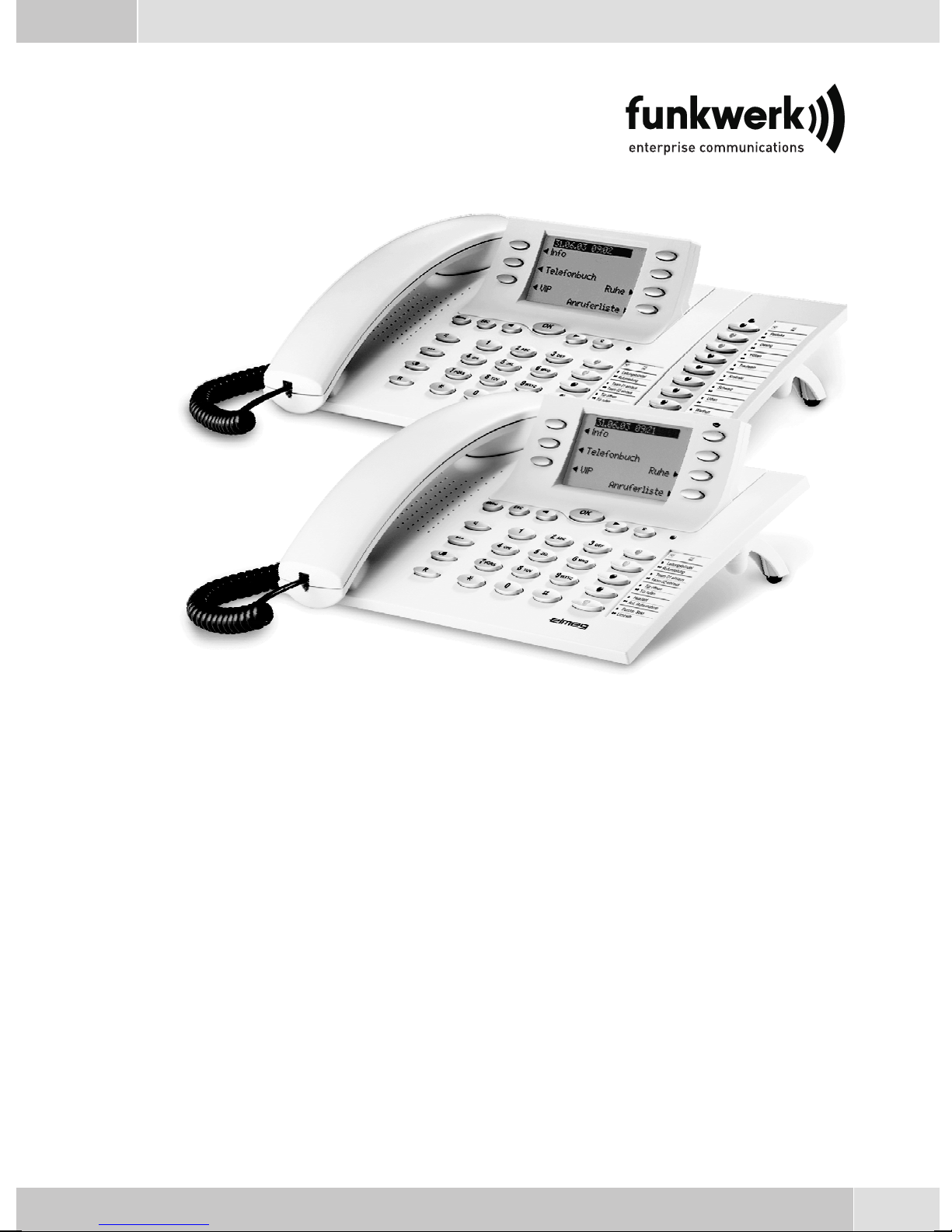
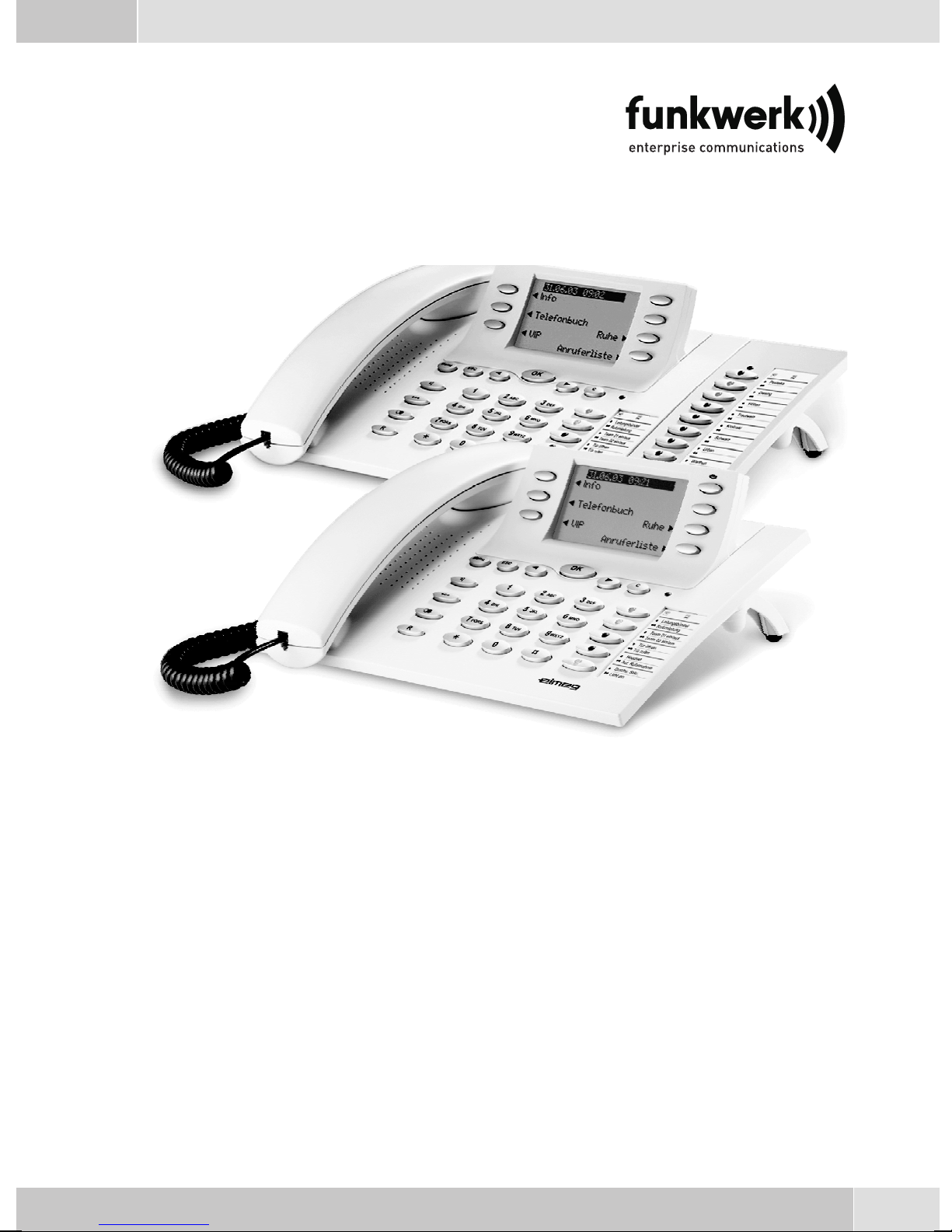
elmeg CS410, CS410-U, CS400xt, IP-S400 Operating Instructions Manual
Operating instructions
Bedienungsanleitung
Notice d'utilisation
Istruzioni per l'uso
Instrucciones de servicio
Bruksanvisning
Brukerveiledning
егчейсЯдйп чсЮузт
Betjeningsvejledning
Instrukcji obslugi
Handleiding
Manual de instruções
elmeg CS410 / CS410-U / CS400xt / IP-S400
English - Deutsch - Français - Italiano - Español - Svenska
Norsk - ЕллзнйкЬ - Dansk - Polski - Nederlands - Português


English . . . . . . . . . . . . . . . . . . . . . . . . . . . . . . . . . . . . . . 1
Telephone display and buttons . . . . . . . . . . . . . . . . . . . . . . . . . . . . . . . . . . . . . . . . . 2
Description and Installation . . . . . . . . . . . . . . . . . . . . . . . . . . . . . . . . . . . . . . . . . . . 3
Making Calls . . . . . . . . . . . . . . . . . . . . . . . . . . . . . . . . . . . . . . . . . . . . . . . . . . . 11
Telephone operation. . . . . . . . . . . . . . . . . . . . . . . . . . . . . . . . . . . . . . . . . . . . . . . 15
Configuration settings. . . . . . . . . . . . . . . . . . . . . . . . . . . . . . . . . . . . . . . . . . . . . . 17
Declaration of conformity and CE mark . . . . . . . . . . . . . . . . . . . . . . . . . . . . . . . . . . . 19
Deutsch . . . . . . . . . . . . . . . . . . . . . . . . . . . . . . . . . . . . . . 1
Display und Tasten des Telefons . . . . . . . . . . . . . . . . . . . . . . . . . . . . . . . . . . . . . . . . 2
Beschreibung und Installation . . . . . . . . . . . . . . . . . . . . . . . . . . . . . . . . . . . . . . . . . . 3
Telefonieren . . . . . . . . . . . . . . . . . . . . . . . . . . . . . . . . . . . . . . . . . . . . . . . . . . . 11
Telefon bedienen. . . . . . . . . . . . . . . . . . . . . . . . . . . . . . . . . . . . . . . . . . . . . . . . . 16
Einstellungen in der Konfigurierung . . . . . . . . . . . . . . . . . . . . . . . . . . . . . . . . . . . . . 17
Konformitätserklärung und CE-Zeichen . . . . . . . . . . . . . . . . . . . . . . . . . . . . . . . . . . . 19
Français . . . . . . . . . . . . . . . . . . . . . . . . . . . . . . . . . . . . . . 1
Afficheur et touches du téléphone. . . . . . . . . . . . . . . . . . . . . . . . . . . . . . . . . . . . . . . . 2
Description et installation . . . . . . . . . . . . . . . . . . . . . . . . . . . . . . . . . . . . . . . . . . . . 3
Téléphoner . . . . . . . . . . . . . . . . . . . . . . . . . . . . . . . . . . . . . . . . . . . . . . . . . . . . 11
Utilisation. . . . . . . . . . . . . . . . . . . . . . . . . . . . . . . . . . . . . . . . . . . . . . . . . . . . . 16
Réglages dans la configuration . . . . . . . . . . . . . . . . . . . . . . . . . . . . . . . . . . . . . . . . . 17
Déclaration de conformité et marque CE . . . . . . . . . . . . . . . . . . . . . . . . . . . . . . . . . . . 19
Italiano . . . . . . . . . . . . . . . . . . . . . . . . . . . . . . . . . . . . . . 1
Display e tasti del telefono . . . . . . . . . . . . . . . . . . . . . . . . . . . . . . . . . . . . . . . . . . . . 2
Descrizione e installazione . . . . . . . . . . . . . . . . . . . . . . . . . . . . . . . . . . . . . . . . . . . . 3
Telefonare. . . . . . . . . . . . . . . . . . . . . . . . . . . . . . . . . . . . . . . . . . . . . . . . . . . . . 11
Rubrica telefonica . . . . . . . . . . . . . . . . . . . . . . . . . . . . . . . . . . . . . . . . . . . . . . . . 16
Impostazioni nella configurazione. . . . . . . . . . . . . . . . . . . . . . . . . . . . . . . . . . . . . . . 17
Dichiarazione di conformità e marcatura CE. . . . . . . . . . . . . . . . . . . . . . . . . . . . . . . . . 19
Español . . . . . . . . . . . . . . . . . . . . . . . . . . . . . . . . . . . . . . 1
Pantalla y teclas del teléfono . . . . . . . . . . . . . . . . . . . . . . . . . . . . . . . . . . . . . . . . . . . 2
Descripción e instalación . . . . . . . . . . . . . . . . . . . . . . . . . . . . . . . . . . . . . . . . . . . . . 3
Telefonear. . . . . . . . . . . . . . . . . . . . . . . . . . . . . . . . . . . . . . . . . . . . . . . . . . . . . 11
Programar guía telefónica. . . . . . . . . . . . . . . . . . . . . . . . . . . . . . . . . . . . . . . . . . . . 16
Ajustes en la configuración . . . . . . . . . . . . . . . . . . . . . . . . . . . . . . . . . . . . . . . . . . . 17
Declaración de conformidad y símbolo CE . . . . . . . . . . . . . . . . . . . . . . . . . . . . . . . . . . 19
Svenska . . . . . . . . . . . . . . . . . . . . . . . . . . . . . . . . . . . . . . 1
Display och telefonens knappar . . . . . . . . . . . . . . . . . . . . . . . . . . . . . . . . . . . . . . . . . 2
Beskrivning och installation . . . . . . . . . . . . . . . . . . . . . . . . . . . . . . . . . . . . . . . . . . . 3
Telefonera. . . . . . . . . . . . . . . . . . . . . . . . . . . . . . . . . . . . . . . . . . . . . . . . . . . . . 11
Telefonkatalog programmering . . . . . . . . . . . . . . . . . . . . . . . . . . . . . . . . . . . . . . . . 16
Inställningar i konfigureringen. . . . . . . . . . . . . . . . . . . . . . . . . . . . . . . . . . . . . . . . . 17
Konformitetsförklaring och CE-märken . . . . . . . . . . . . . . . . . . . . . . . . . . . . . . . . . . . 19
I

Norsk . . . . . . . . . . . . . . . . . . . . . . . . . . . . . . . . . . . . . . . 1
Telefonens display og taster . . . . . . . . . . . . . . . . . . . . . . . . . . . . . . . . . . . . . . . . . . . 2
Beskrivelse og Installation . . . . . . . . . . . . . . . . . . . . . . . . . . . . . . . . . . . . . . . . . . . . 3
Telefonering . . . . . . . . . . . . . . . . . . . . . . . . . . . . . . . . . . . . . . . . . . . . . . . . . . . 11
Betjening av telefonen . . . . . . . . . . . . . . . . . . . . . . . . . . . . . . . . . . . . . . . . . . . . . . 16
Innstillinger i konfigureringen . . . . . . . . . . . . . . . . . . . . . . . . . . . . . . . . . . . . . . . . . 17
Konformitetserklæring og CE-merker. . . . . . . . . . . . . . . . . . . . . . . . . . . . . . . . . . . . . 19
ЕллзнйкЬ .....................................1
Пиьнз кбйРлЮкфсб фзт фзлецщнйкЮт ухукехЮт ................................2
РесйгсбцЮ кбй егкбфЬуфбуз...........................................3
ЧсЮуз фзлецщнйкюн ухукехюн.........................................12
Чейсйуµьт фзлецюнпх ..............................................17
ЕрйлпгЭт фщн схиµЯуещн ............................................19
ДЮлщуз ухмцщнЯбт кбй уЮмб CE........................................21
Dansk . . . . . . . . . . . . . . . . . . . . . . . . . . . . . . . . . . . . . . . 1
Display og telefonens taster . . . . . . . . . . . . . . . . . . . . . . . . . . . . . . . . . . . . . . . . . . . 2
Beskrivelse og installation . . . . . . . . . . . . . . . . . . . . . . . . . . . . . . . . . . . . . . . . . . . . 3
Telefonering . . . . . . . . . . . . . . . . . . . . . . . . . . . . . . . . . . . . . . . . . . . . . . . . . . . 11
Betjening af telefonen . . . . . . . . . . . . . . . . . . . . . . . . . . . . . . . . . . . . . . . . . . . . . . 16
Indstillinger i konfigurationen . . . . . . . . . . . . . . . . . . . . . . . . . . . . . . . . . . . . . . . . . 17
Konformitetserklæring og CE-mærke . . . . . . . . . . . . . . . . . . . . . . . . . . . . . . . . . . . . . 19
Polski . . . . . . . . . . . . . . . . . . . . . . . . . . . . . . . . . . . . . . . 1
Opis i instalacja ..................................................2
Opis i instalacja ..................................................3
Wykonywanie po³¹czeñ .............................................11
Obs³ugiwanie telefonu..............................................16
Ustawienia w konfiguracji ...........................................17
Deklaracja zgodnoœci i symbol CE .......................................19
Nederlands . . . . . . . . . . . . . . . . . . . . . . . . . . . . . . . . . . . . 1
Display en toetsen van de telefoon . . . . . . . . . . . . . . . . . . . . . . . . . . . . . . . . . . . . . . . 2
Beschrijving en installatie . . . . . . . . . . . . . . . . . . . . . . . . . . . . . . . . . . . . . . . . . . . . 3
Telefoneren . . . . . . . . . . . . . . . . . . . . . . . . . . . . . . . . . . . . . . . . . . . . . . . . . . . . 11
Telefoon bedienen . . . . . . . . . . . . . . . . . . . . . . . . . . . . . . . . . . . . . . . . . . . . . . . . 16
Instellingen in de configuratie . . . . . . . . . . . . . . . . . . . . . . . . . . . . . . . . . . . . . . . . . 17
Conformiteitsverklaring en CE-teken . . . . . . . . . . . . . . . . . . . . . . . . . . . . . . . . . . . . . 19
Português . . . . . . . . . . . . . . . . . . . . . . . . . . . . . . . . . . . . . 1
Display e teclas do telefone . . . . . . . . . . . . . . . . . . . . . . . . . . . . . . . . . . . . . . . . . . . . 2
Descrição e instalação. . . . . . . . . . . . . . . . . . . . . . . . . . . . . . . . . . . . . . . . . . . . . . . 3
Telefonar . . . . . . . . . . . . . . . . . . . . . . . . . . . . . . . . . . . . . . . . . . . . . . . . . . . . . 11
Operar o telefone. . . . . . . . . . . . . . . . . . . . . . . . . . . . . . . . . . . . . . . . . . . . . . . . . 16
Ajustes na configuração . . . . . . . . . . . . . . . . . . . . . . . . . . . . . . . . . . . . . . . . . . . . . 17
Declaração de conformidade e o símbolo CE . . . . . . . . . . . . . . . . . . . . . . . . . . . . . . . . . 19
II
Operating instructions
elmeg CS410 / CS410-U / CS400xt / IP-S400
English
1
English
7
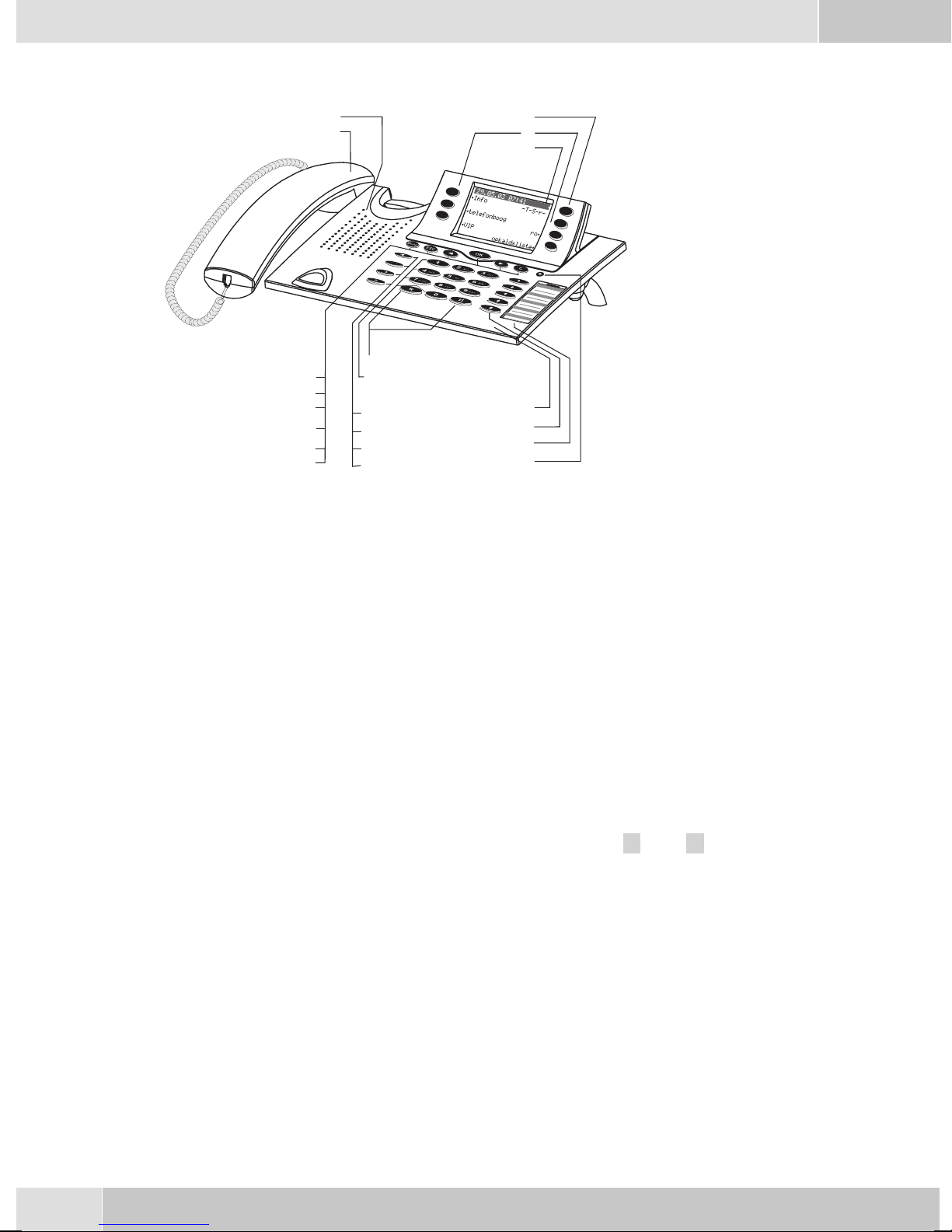
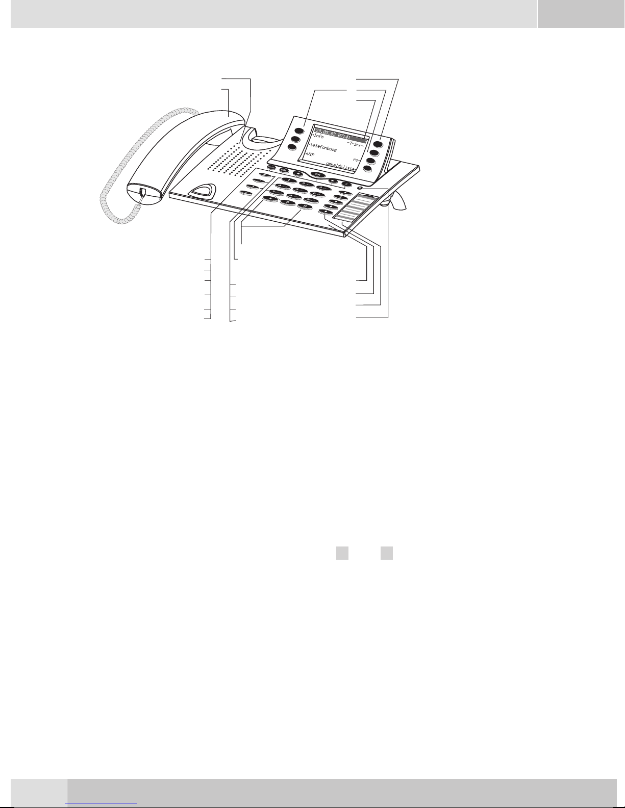
Telephone display and buttons
Figure 5
1 Speaker
10
11
1
2
3
4
5
12
6
7
8
9
13
14
15
16
1
18
19
20
21
2 Handsetwith connectingcord
3 Answering machine buttonon thetelephone (optionalmodule) or »PABXmenubut-
ton
4 6Softkeys
5 Seven-linebacklit display
6 Menukey:Thiskeyopenstheprogrammingmenu. Ifyouarealready locatedinamenu
and then press the key, eithermenu-specific functions are shown, or you are moved
backone programmingstep.
7 ESCkey: PressingtheEsc button duringprogrammingreturnsthetelephoneto itsidle
status.
8 / 10
9 OKkey: Pressingthis buttonconfirmsan entryor storesa settinginthetelephone.
11 Ckey:Pressthisbuttontomovebackonemenustep inthemenu. Ifyouare currentlyin
12 Asteriskkey/ hashkey
13 Dialbuttons
14 Openlistening/ hands-freebutton
Arrowbutton »Totheleft« /»To theright«:Thearrows » {«and »} «inthe rightcor
neronthetoplineofthedisplayindicatethatyoucancallupfurtherfunctionsonthelo
werlines usingthearrow buttons.
theinput mode,this buttoncan beused todelete individualcharacters.
-
-
15 Endinga call
16 Redialbutton
17 Enquirybutton
18 Microphone
2
English
19 Five programmable function keys with LED: Eachbutton hasan insettwo-color LED
(level1 -red /level2- yellow).TheseLEDs can beusedto indicatecertain functions.
20 Labelpanel forfunction keys
21 Callsignaling (red)and answeringmachine(yellow) LED
Description and Installation
These operating instructions describe onlythe most important routines for using the telephone.
Detailed information and documentation can be found on the CD-ROM.
CS410
This systemtelephone isdesigned for connectionto an internal S0-port(4 wires) of anelmeg pabxsystem.
If youwish toconnect the telephoneto aninternal Up0-port, besure toinstall the internal Up0/S0-module
into the telephone or use the external Up0/S0-converter.
CS410-U
This system telephone is designed for connection to an internal Up0-port (2 wires) of an elmeg pabx sys
tem. The internal Up0/S0-module or the external Up0/S0- converter are then no longer required.
CS400xt
Thissystem telephoneisdelivered withakey extensionmodule(T400/2), providingyouwith 10additional,
freely configurable keys.
Itis designedfor connectionto aninternalS0 port(4-wire cable)ofa PABXsystem. Thesystem telephoneis
not equipped witha USB or serial portfor configuration or other uses. This phone must be configured via
the internalISDN port usingthe WinToolsProfessional Configurator.There arealso no»Audio functions«
implemented and you can not use the Answering machine or Up0 modules or functions. None of the
functions for this module are shown in the display, nor can they be used.
Thistelephone isequipped withthe function»Emergency operation«,mea
OFF
ON
ning it can be operated at NT via the PABX system on a loss of 230 V~ po
wer.Please notethat yourPABX systemsupports thisfeature andthat itcan
not be used via a Up0/S0 converter.
elmeg IP-S400
-
-
-
Connectthis systemtelephoneto thecorresponding LANport(or network)ofthe PABXsystem usingaCat.
5cable. Thesystemtelephone isequippedwith aPC outputthatcan beusedto connectotherIP terminalde
vices.
Setting up/ Configuring the system telephone
On the system telephoneitself you can only carry out a limitedconfiguration of the supported features. A
fullconfiguration isonly possiblewithan elmegtelephonesystem usingthe professionalWINtool configu
rator via the corresponding system telephone interface.
You will find additional information on the configuringof the system telephones in the detailed
instruction manual on the CD-ROM.
-
-
3

English
System telephone extension modules
Modul Up0/S0(CS410)
•
Answeringmachine module(CS410)
•
Additional »T400«,»T400/2«keyboard (CS410,IP-S400)
•
Safety notes
Mind the storage and operation temperatures for the devicelisted inthe technicalspecifications.
•
Only connectthe devicewhen thepermissible ambientoperating temperaturehas beenreached.
Please notethat condensation onor in theunit must beprevented whenmoving from coldto warm
•
surroundings.Only removethe unitfrom thepackage whenthe permissibleambientoperating tem
perature hasbeen reached.
You should not make calls or connect or disconnect any linesduring thunderstorms.
•
Only attach theconnecting cordsat the connectionsprovided.
•
Make surephone cablesare installedin asafe mannerto preventtripping.
•
Avoid the following:
•
Direct sunlight
Sources ofheat (forexample radiators)
Electronic devices (for examplestereo components,office equipmentor microwavedevices
Ingress of moistureor liquids
Aggressive fluids or vapors
Dusty environment
-
• Do not usethe unitin excessivelyhumid roomsor hazardous locations.
• Only openthose sectionsof thedevice specified in theassembly /operating instructions.
• Do not touch plug connectors withpointed, metal, or moist objects.
• Ifyou donot permanentlymount thedeviceor anyaccessories, besureto placeit/them ona non-slip
surface.
•
When required, clean theunit witha slightlymoistened cloth.
•
Only useapproved accessories.
•
Onlyterminals withSELV and/orwhich complywithETS 300047may beconnectedto theunit. This
regulation is fulfilled whenapproved terminal devices are used as intended.
Plug-in power supply
•
Use only approved power plug-inunits (DSA-0101F-05 UPor L15D52 ABDDLAWO).
•
Do not usepower plug-inunits withvisible defectsor damage(fissures, cracks, etc.)
Elektrostatic charges
The telephone is supplied with enhanced ESD protection against theeffects of electrostatic discharge that
exceeds theprotection level cited in theapproval specification. Elevated ESDlevels should neverthelessbe
avoided to the greatest possible extent. In some cases, electrostatic discharge levelscan far exceed the ap
proval limitsor the resistance levelsalready implementedin your telephones.Eliminate the causes orcon
ditions that promote these elevated ESD levels, such as insufficient humidity or carpeting. The telephone
manufacturer does not assume any liability for damage caused under such circumstances.
-
-
4
Unpacking and placing the telephone
Unpacking
ISDN system telephone
•
Handset with handset connecting cord
•
2 feet
•
ISDN connectingcord (approx.6 m)
•
PC-Connection cable(USB, ca. 3M), (notwithCS400xt)
•
PC-audio cable(3.5mm stereo plug, ca. 2.5m), (notwithCS400xt)
•
Adapter cordfor headsetswith a4 pinconnecting cord(8 pin/ 4pin)
•
Cable holder (self-adhesiveafter removingthe film), (not withCS400xt)
•
Operating instructions and labels for functionkeys
•
WIN-Tools CD-ROM with:
•
Professional Configurator, telephone, Download and Sound Manager,
TAPI-, USB-, CAPI-and NDISWAN-drivers, AdobeAcrobat Reader,
Operating instructions and Adobe Acrobat filefor theprinting ofindividual labels
English
Placing the telephone
Before placing the telephone, mount the rear feet at the positions (6) shown in figure 6.
Please notethat theplastic feetof your ISDNsystem telephonemay leavemarks on sensitivesurfaces, such
as furniture. The manufacturer of the ISDNsystem telephoneis notliable forany suchdamage. Therefore,
use appropriate non-skidding pads under the phone.
Cleaning the telephone
The ISDN system telephone has been manufactured for normal, everyday use. When required, clean the
ISDN system telephone witha slightly moistened cloth, or with an anti-static cloth. Never use a solvent to
clean thephone! Neveruse a drycloth. Electrostatic chargescould damagethe electronics inthe system. It
is essentialthat no liquidspenetrate into the insideof the ISDN systemtelephone, as this coulddestroy the
phone.
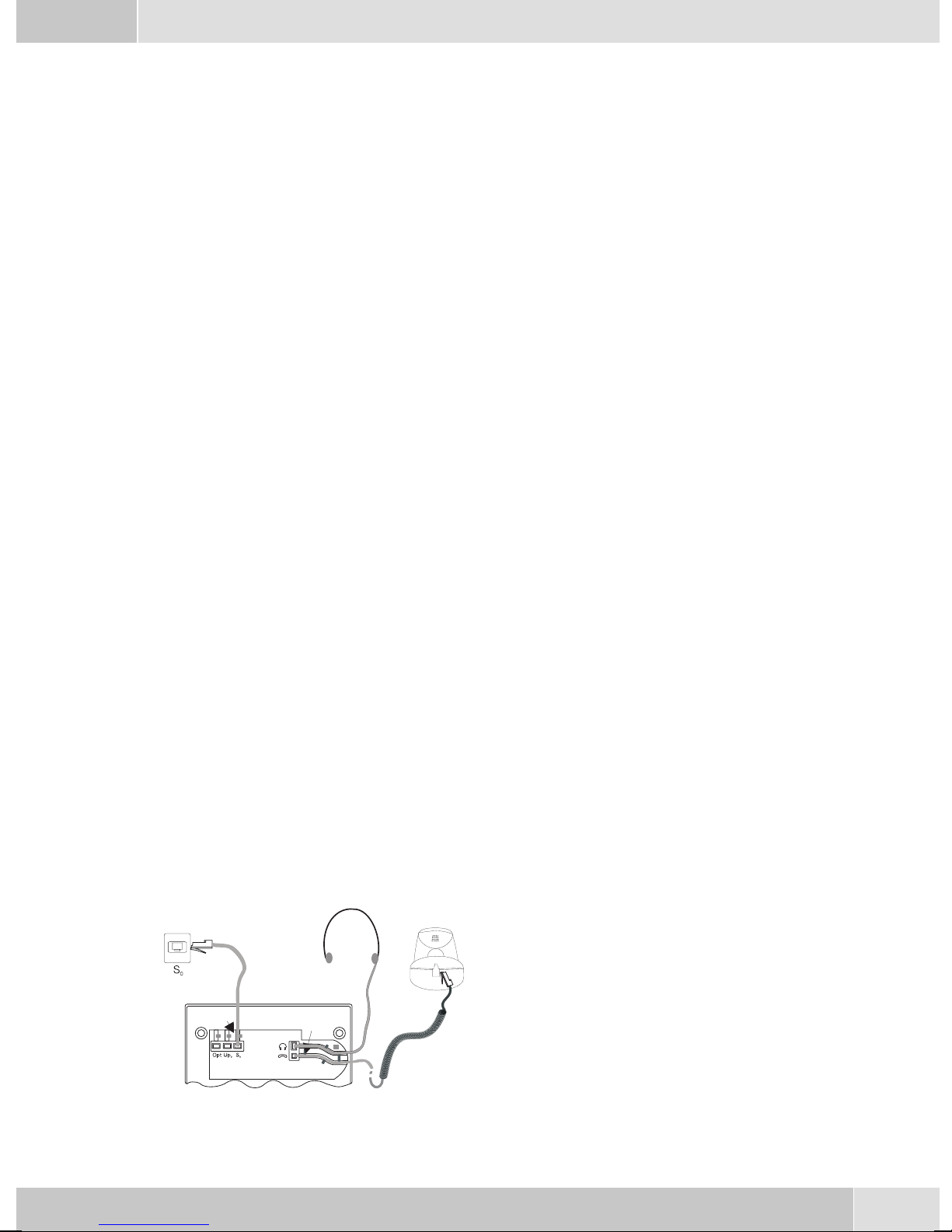
Connecting the telephone (ISDN and handset cords)
Pleaseconnect theISDNcable andthe handsetcable.Otherwiseyou willnotbe abletooperate thephone.
Connecting the handset connecting cord
Connect the handset cord (1) as shown in figure 6.
Lay the handsetcord inthe cordgroove (4)and lock
it below the two cord retainers (5).
2
4
6
5
5
4
Figure 6
3
6
4
7
1
5
English
Connecting the ISDN cord
Connection to the S0 (CS400xt CS410)
Connect the ISDN cord (2) as shown in figure 6 (S0-connector). Ensure that thelonger ISDN connector is
plugged into theISDN socket and theshorter ISDN connectorinto theISDN socket onthe telephone. Then
lay the ISDN cord in the cord groove (4) and lock it below the two cord retainers (5).
Connection to the Up0 (CS410-U)
Connect the ISDN cable (2) as shown in figure 3
(Up0-socket). Ensurethat the longerISDN connec
tor is plugged into the ISDN outlet and the shorter
ISDN connector into the ISDN socket on the tele
phone. Then lay the ISDN cord in the cord groove
(4) and lock it below the two cord retainers (5).
Figure 3
2
1
3
5
4
-
-
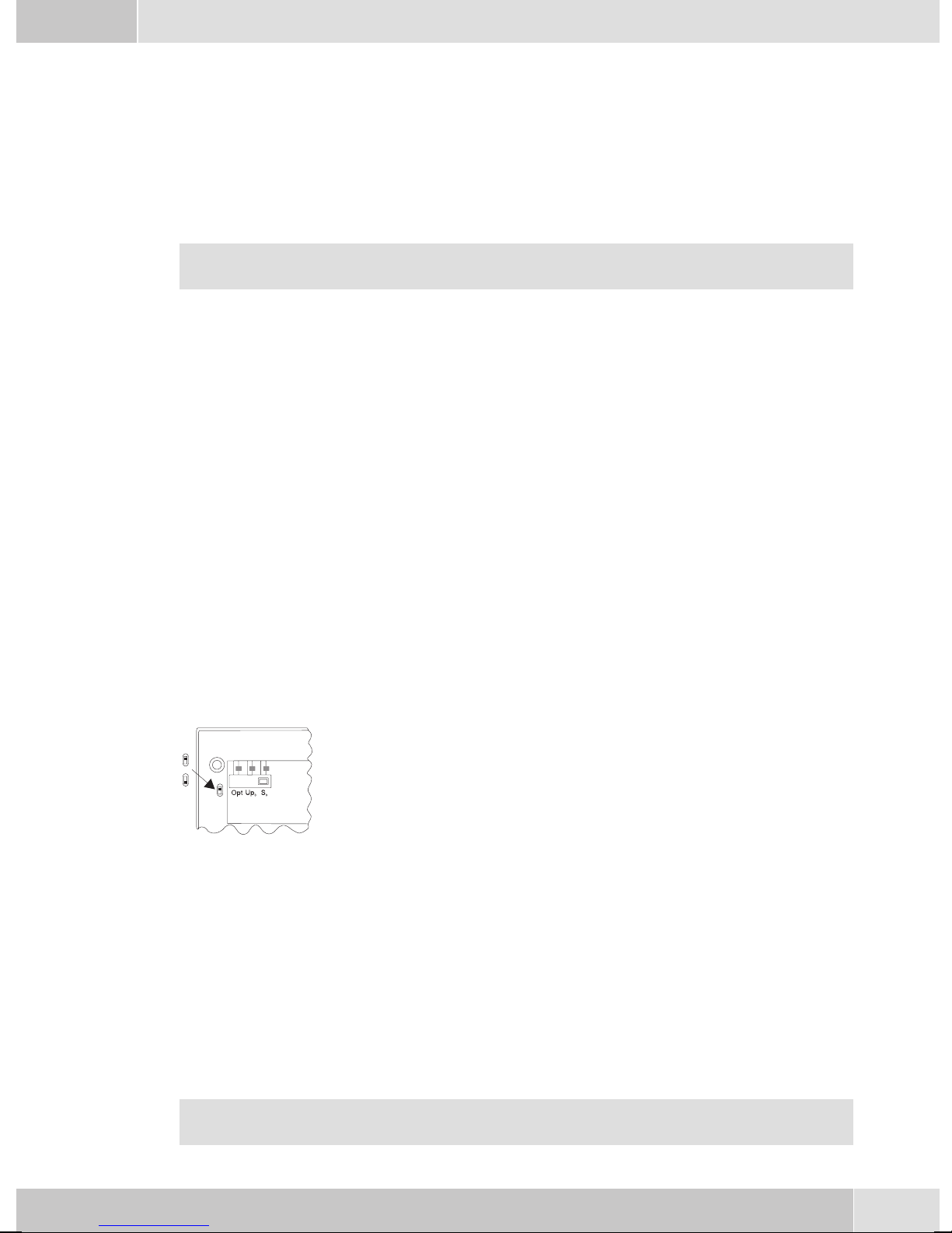
CS410 telephones equipped with a Up0/S0 module or CS410-U phones may not be connected
through the S
Important notes for the UP0-connection
• An ISDN terminaldevice equipped with S0-port can beconnected to thephone's S0-jack.
• The maximumline distance betweenthe elmeg CS410-Uand anydownstream ISDN terminal devi-
ces may not exceed 10 meters.
• Terminatingresistors may not beconnected.
0-socket (3) to the ISDN connection (e.g. internal ISDN port of the PABX) .
elmeg IP-S400 at the Ethernet-port
1
-
Connection for plug-in power
supply unit
2
-
Plug-in power supply unit
3
-
Ethernet PC-Connection
4
-
PC or other IP-telephone
5
-
Ethernet-port of the pabx
Figure 4
6
6
-
elmeg pbx

English
Connecting to and operating the system telephone at the pabx system (basic function including
DHCP)
Consult theinstallation instructionsfor the PABXsystem todetermine which port can beused forconnec
ting the IP-S400. Connect this port with the Ethernet PABX port on the system telephone.
Configure your PABXsystem for usewith IPsystem telephones.
•
Define the MSNs for the IP system telephones withinthe PABXsystem.
•
Switch on the power(plug-in power supply unit)to the IP system telephoneand wait until thetele
•
phone has been initialized.
Oncethe IPsystem telephonehasbeeninitialized youwillbe requestedtoselect thelanguage inthe display.
Select the display language.
•
Press the buttons to view the available langua
ges.
-
Italiano
Deutsch
Française
Which Country? }
Español
®English
Nederland
• Enter one ofthe MSNs that has beeninput tothe PABXsystem (inthe exampleshown here,12) .
Confirm your entry by pressing
. Programm dial number
O
-
-
MSN-1>12
If no PIN has been entered in the system configuration, press button
again after being requested to do so.
O
O
and button
IPS login PIN for sys
server
MSN-1>
• Swtich to UseDHCP.
Select »on«. Use automatic IP
adress setting
off
on®
•
The telephoneand PABXsystem are synchronized.
If there is no connection tothe PABX system (noLAN link, or the telephone has not beenlogged
in),the symboll» -----/ /----‰ «willbe shownin thedisplay insteadofthe time.
You can now use the IP system telephone at the ISDN or UP0 port.
Changing the label
Thelabels forthe functionkeys areprovided onthe lastpage ofthis operatingmanual. Cutout thelabel you
wish to use.
To changethe label panel,press the flexiblecover together between your indexfinger and thumband lift it
out. The label panel can now be changed.
You can fillin thelabel panelvia yourPC yourself.The CDROM suppliedwith thesystem containsan Ado
be Acrobat file with templates.
-
7

English
Pictograph
The pictographs (symbols)described asfollows havebeen usedin these operating instructions to illustrate
some petting and using the telephone.
b Liftup thehandsetorstart initializingselection.
a Replacehandset. Thetelephoneisidle.
l Acall issignaled.Theringing tonemelody sounds.
g Youare conductingacall.
d Athree-party conferencecallisinitiated.
q Youhear thepositiveornegative acknowledgementsignal.
t Selectthe number,code, characteror text.
09
Pressthe appropriatebutton onthepush-buttonset.
*#
Country-specific settings
Certain specificparameters need to be setif the telephoneis to beused in a country other than thecountry
configured as default.
This includes setting the language, the currency and certain default specific parameters for a country’s
ISDN network.
Check as describedas followswhether youneed toset country-specificparameters forthe countryin which
the telephone is to be used.
Begin as follows:
a
Ms s
Konfigu
ration
-
Service
s Press the arrow keys to view the countries, for
which specific settings are available.
Press the softkey for the desired country. For
example: »English«.
t
Telephone PIN
O>s
Country
Which Country? }
Italiano
Español
Deutsch
®English
Française
Nederland
All country-specific settings take effect imme
diately. The telephone data will not be dele
ted.
8
-
29.05.06 07:41 }
-
Tel. drctry
Quiet
VIP
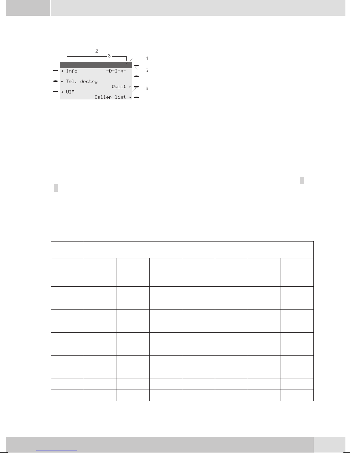
Telephone display
English
1
2
3
09.03.06 07:00
4
5
6
Figure 5
The telephone is equipped with a seven-line backlit display. Backlighting is automatically switched on or
off.
After you connect the system to the internal ISDN connection of your pabx system, the date and time are
shown on thetop line of the display. The date and time are imported automaticallyfrom the pabx system.
The text displayed for a function is always located next to the corresponding softkey. Whenyou press the
softkey, thenext level isdisplayed. If not allinformation fit intothe screen, thiswill be indicatedby »««or
»««. To view further characters, press the R key and then use the corresponding arrow key.
Date
-
Time
-
21 characters per line
-
Arrow: Further menu items accessible by using the ar
-
row keys.
Answering machine button on the telephone (optional
-
module) or »PABX menubutton
Arrow: Indication of the softkey that can be used in the
-
current menu.
-
Various telephone display shots are illustrated in this operator’s manual to help explain the different settingsand useofthe system.A wavyline atthetop orbottom ofan illustrationindicates thatnot allof the 7lines of that particular display are shown (only pertinent lines shown).
Use the buttons as follows when entering texts, letters digits or special characters:
Key Press
Key
1
2
3
4
5
6
7
8
1234567
1
ABC2ÄÅÆ
DEF3 €
GH I 4
JKL5
MNO 6 ÖØ
PQRS 7 ß$
TUV8Ü
9
*
#
WX Y Z 9 ¥
*
#
9
English
0 Several special charactersare assignedto thebutton »0«.For specialcharacters, press
the0 key.
Forexampe.: »!«, »&«, »?«,»+«,»-«, »=«,»(«,»)«,»@«, »$«, ...
Input mode for entering letters
You havevarious possibilitiesfor enteringletters. The currentlyset inputmode is displayed on thetop half
of the display on the right-hand side (no display, »Abc« or »ABC«).
»Abc« Thenextletterthatyouenterisshownasacapital,all othersassmallcaseletters.Exam
ple:»Dean, James«.
no display Everyletter thatyouenteris showninsmall case.
Example:»dean, james«.
»ABC« Everyletter thatyouenteris shownascapitals.
Example:»DEAN, JAMES«.
When you startentering texts,the input mode is always»Abc«. Pressthe Rkey to changethe in
put mode. To insert a character while in »Abc« mode, press the C key.
Displays for programmed features
s When the telephone is in the idle state, addi-
tional information about functions that have
been configured are shown on »Info« line
of the display. In this example:
»-D-I-q-«.
Press the softkey next to »Info« if you wish
to get more information about the configured
functions.
If you have programmed several features,
press the arrow buttons to view the various
settings.
29.05.03 07:21 }
Info -D-I-q-
Tel. drctry
Quiet
VIP
Caller list
ªªªªªªªªªªªªªªªªªªªªªª
Inhibit/Menu:
Guard for modificatio
¬¬¬¬¬¬¬¬¬¬¬¬¬¬¬¬¬¬¬¬¬¬
-
-
Display Configured function
»-D-«
»-I-«
Active appointment reminder set.
Dial ranges or call filter active,
Access to telephone menus is protected.
»-q-«
»-Q-«
Function »Station guarding« (only brief signal) active.
Function »Station guarding« (complete) active.
(All call signals are switched off)
»-U-«
» -i- «
Call forwarding active.
Information about programmed function keys
For example: Message enabled / inhibited.
» --«
Answering machine,time control, call forwardingsignaling orremote controlare ac
tivated (optional module).
10
-
English
Making Calls
Starting a call
Dial number - no correction possible
btg
Dial number
Dial number - correction possible
atbg
Dial number
To changethe numberor tocorrect awrong entry,select thewrong figurewith thearrow buttonsand press
C key to delete it. Now enter the correct number.
If youwish to conduct the callusing the handset,just lift it up afterdialing the number. Any time during a
call you can switch back and forth between hands-free calling, speaker function and use of the handset.
After you have dialed the number you can also press the speaker button to have the number dialed and to
use hands-free calling.
If a call can not be put through(e.g. number is inhibited via the dial ranges control, or the account for the
number/MSN isempty), a correspondingmessage will appear inthe display. Forexample: »Inhibit.
: MSN ext.«, when the dial range filter is active.
Other options for dialing without lifting the handset
The option ofdialing withoutlifting thehandset andof correcting or addingto anumber alsoexists during
dialing:
• from the redialing memory.
• from the caller/ memolist.
•
from the telephone directory.
•
from the VIP memory.
•
from the direct dialing memory.
•
via CTI, TAPI (CS 410) features.
Ifyou areusing oneof theseoptions, youcan makefurther entriesprior toinitiating thecall. You candefine
which number (MSN), if any, is to be transmitted to the party being called.
Dialing from the pabx telephone directory
When you use this telephone witha system telephony supportingpabx system, you can dial from the tele
phone directory of the pabx.
a
Rs
drctry
Tel.
t
Enter first
letter
O<>O
Select
entry
-
b
11
English
Dialing from the phone’s directory
You can store up to 250 names and numbers in the telephone directory. To select a name, you can page
through the directory using the arrow buttons, or enter the specific first letter(s) of the name using the
push-button set.
a
For informationon how to program andconfigure the telephonedirectory, please refer to page 15 ofthese
operating instructions.
Dialing from the VIP memory
Youcan programVIP numbersfor eachofthe tenbuttons1 …0 includinga name(20characters max.) and
a telephone number (26 digits max.).
a
For information on how to program VIP entries, please refer to page 16 of these operating instructions.
Direct dialing with function keys
Direct dialing is initiated using the direct dialing keys. Each of the keys can be programmed with two
functions or direct dialing numbers.
s
Tel. drctry
s
VIP
t
Enter first letter Select entry
O<> O
or
Select
VIP
destina
tion
-
Select VIP
destination
bg
tbg
a
Use the function keys to select the desired number.
Ifyou wishtodial anumberfrom thesecond level,press thecorrespondingkey twotimes. This mustbeexe
cuted at a short interval.
You canprogram thedirect dialing/ functionkeys viathe PCconfiguration programor theextended confi
guration of the telephone.
Dialing from the caller/memo list
The phone has a combinedcaller andmemo list. A maximum of 30 entries (calls, memosSMS messagesor
UUS1- messages) are stored in this list. Entries in thecaller or memo list are indicated by the »Caller
list« softkey.
a
Further functions
Accepting/rejecting a call
Z
Press the function key
s
Caller list
bg
b
Select entry
albg
-
-
12
Rejecting a call
English
al
Forwarding a call (call deflection)
al
Calling line identification (anonymus call) restriction
at
Dial number
OM s
al
Starting a call with a set number (MSN)
at
Dial number
OMs s
s
transfer
s
Concealed
MSN MSN-1 ...
t
Dial number
Concealed
bg
MSN-10
s
reject
O
bg
bg
Extended redialing
In the extended redialing the numbersof the last 20 calls, connections (conversations) and text messages
are stored. You can view these by pressing the redial button or the arrow buttons and subsequently have
them redialed automatically.
a
Automatic redialing
If youplaced acall to asubscriber whosenumber isbusy or whodoes notanswer, you can thenactivate au
tomatic redialing which will call that same subscriber again after about 10 seconds.
btg
Dial number Subscriber
Deactivating automatic redialing
a
WWO
Select entry
or
W
busy
ss
Autom.repeat request Yes
bg
s
Autom.repeat
request
a
-
Activating/ muting the microphone
g
s
Mute speak
Room enquiry
s
g
13
English
Speaker function
g
Hands Free Calling
a
Begin hands free calling Dial number End hands free calling
Headset use
For headsetoperation, oneof thefunctions buttonsmust beconfigured asa headsetkey. TheLED assigned
to this key indicates, whether the headset in switched on or off (LED on or off).
a
Message
a
Intercom
z
activate headset Dial number Call via headset deactivate headset
Ms>s
LL
Begin open listening End open listening
L
tg
Acou
stic
t
Message
tg
Dial internal
number
g
L
z
message
a
Automatic completion of call
Ms>s
btg
Dial number Subscriber busy or
Keypad
g
Tone Frequency Dialing (DTMF dialing)
g
Conducting calls with several parties
Call waiting
Acou
stic
does not answer
s
Keypad
s
dtmf
tg
Inter-
com
Dial internal
number
s
Clbckbusy
t
Input of character strings and digit
sequences
t
Input of character strings and digit
sequences
intercom
a
g
Call with subscriber 1
14
waiting call
(subscribers 2)
s
accept
g
Call with subscriber 2;
Party 1 is put on hold
Enquiry Call
English
g
Call with subscriber Party 1 is put on hold Dial number Call with subscriber 2
Call transfer (switching)
g
Call with subscriber 1 Party 1 is put on hold Dial number Call with subscriber 2
Broker’s call
g
Call with sub
scriber
Three-party conference
g
Call with subscriber
1
>s
-
>s
R
Connection 1
Connection 4
R
...
Connection 2
Call with desi
red subscriber
tg
g
Call with subscriber
tg
transfer
>s
-
g
Connection 1
Connection 4
...
s
Conferen
2
ce
-
Call with desi
red subscriber
Conference with
subscribers 1 and 2
s
g
-
d
Telephone operation
Telephone directory
You can store up to 250 names and numbers in the telephone directory. To select a name, you can page
through the directory using the arrow buttons, or enter the specific first letter(s) of the name using the
push-button set.
If the nameof the caller is to be shown in the displayinstead of the caller’s number, this number
mustbe enteredinthe telephonedirectory withthat name(includingprefixand, whenused witha
PABX, the line access digit).
Display ofthe callername isonly madewhen thetransmitted numbercorresponds tothe number
stored in the phone directory.
Ifthe telephoneisdisconnected fromthe ISDN networkand thenreconnected,or ifthedata forthe telepho
ne directory are transferred tothe systemtelephone viathe PCprogram, thedirectory mustbe reorganized
internally. This processtakes place automatically andmay requirea fewminutes. During thistime, thete
lephone directory of your telephone is not available for use.
Settings for telephone book entries
•
Name and number
•
Outgoingnumber (MSNassignment)
-
-
•
Special dial (VIP tone)tone
•
Info text
15
English
Adding an entry to the telephone book
Begin as follows:
a
t Enter the name.
In this example: »Dean«.
Confirm your entry by pressing
t Insert a number.
In this example: »0123456«.
Confirm your entry by pressing
Msss
Program nos. Tel. drctry New
Input telephone book
.
O
O
.
Name>Dean_
¬¬¬¬¬¬¬¬¬¬¬¬¬¬¬¬¬¬¬¬¬¬
Input telephone book
Number>0123456_
¬¬¬¬¬¬¬¬¬¬¬¬¬¬¬¬¬¬¬¬¬¬
VIP Memory
Youcan programVIP numbersfor eachofthe tenbuttons1 …0 includinga name(20characters max.) and
a telephone number (26 digits max.).
Making an entry into the VIP memory
Begin as follows:
a
t Enter the name of the VIP target. In this ex-
t Insert a number.
Station guarding
Ifyou donot wishcallsto besignaled withthe programmedmelodyand volume,you canactivethe »Station
guarding«feature. Dependingonthe specificsetting, allcallswill bedisplayed opticallyor alongwith abrief
acoustic signal. In theidle state an »q«or»Q« in thedisplay shows that thefunction »Station guarding« is
activated.
»No« Thefunction »Stationguarding« isdeactivated.
M s s s <> O
Program nos. VIP New
ample: »Dean«.
Confirm your entry by pressing OK.
In this example: »012345«.
Confirm your entry by pressing OK.
Program VIP name
V0>Dean_
¬¬¬¬¬¬¬¬¬¬¬¬¬¬¬¬¬¬¬¬¬¬
Program VIP number
V0>012345_
¬¬¬¬¬¬¬¬¬¬¬¬¬¬¬¬¬¬¬¬¬¬
Select VIP
destination
»Ringing
signal off«
»ok« Calls are signaled first by a brief acoustic signal and then only optically displayed
16
Callsare signaledopticallyonly(»Q« showninthedisplay).
(»q«).

English
a
ss
Quiet No/Ringing signal off/ok
Configuration settings
Telephone numbers (MSN extension numbers)
Up to 10 MSN (extensionnumbers) can beconfigured on your telephone. When you enter anMSN or ex
tensionnumber inyour ISDNsystemtelephone youare essentiallydefiningthat yourISDN systemtelepho
ne iscalled using this MSNor extension numberwhen a call ismade. If youenter more than oneMSN ex
tension numberin your telephone,your phone willring each timeone of theseMSN extension numbersis
called.
Ifyou areusingyour telephoneonthe externalISDNport ofa pabx,enter itsinternalextension numberinto
the pabx. Please observe the instructions in the PABX manual.
When you calla subscriber,you can selecta certainnumber (MSN) thatis transmittedto the subscriber(e.
g. for separate charges). If you do notselect any number,the number (MSN) thathas been enteredfirst in
the phone (MSN-1) is used.
How to configure an MSN (extension number) is described as follows for »MSN-1«.
Begin as follows:
-
-
-
a
Entering or viewing an MSN extension number (MSN)
You can only enter the MSN extension numbers with the Professional Configurator supplied on the
WIN-Tools CD-ROM. However, you can have the programmed number displayed at the phone.
In the »Program MSN-1« menu, press the »MSN ext.« softkey.
O The programmed number is displayed.
Press OK to leave this menu.
You can onlymake further settings (e.g. call signalingmelody, volume, name) if the numberhas
already been previously configured.
Msss
Configurati-
on
Program MSN-1 }
transfer
MSN Name
MSN ext.
Program MSN-1 }
MSN-1:222
¬¬¬¬¬¬¬¬¬¬¬¬¬¬¬¬¬¬¬¬¬¬
MSN MSN-1
Volume
Sound
More settings for each MSN extension number (MSN)
s »Sound« Setting the melody
17

English
s »Volume« Setting the volume
s »transfer« Programming a default call forwarding number
s »MSN name« Assign a name to the MSN extension number
s »Charge« Programming a charge limitation for a specific extension number
(MSN)
s »PIN« Assign a specific PIN for an externsion number (MSN)
Reset - Resetting to default state
You canreset the telephoneto its initial state usingthe procedure described as follows. All of thedata that
you have entered previously will be deleted.
If you have connected the elmeg T400, T400/2 key extension module to your phone all of the data for the
module will also be deleted when this procedure is executed.
Please note: Settings for the answering machine and any texts that have been stored will not be deleted.
Please refer also to the instruction manual supplied with your answering machine.
Begin as follows:
a
Ms s
Configu
ration
-
Service
s Press »ok« to reset the telephone to its initial
state. If you do not wish to have the data dele
ted press »No«.
When you press the »ok« softkey, the tele
phone is reset to the default state. All data are
deleted.
t
Telephone
PIN
-
-
Oss
Data ok
Sure to delete all?
No
^ok
¬¬¬¬¬¬¬¬¬¬¬¬¬¬¬¬¬¬¬¬¬¬
Which language }
Italiano
Español
Deutsch
English
Française
Nederlands
18
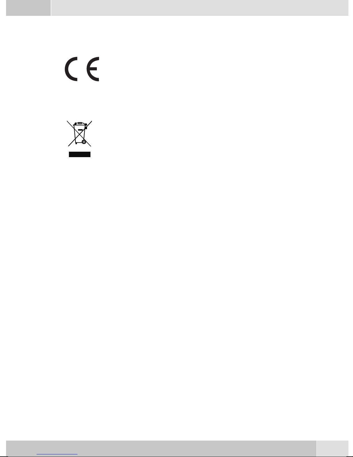
Declaration of conformity and CE mark
This device meets the requirements of the following EC directive R&TTE 1999/5/EG:
»Directive 1999/5/EC of the European Parliament and of the Council of 9 March
1999 onradio equipmentand telecommunications terminalequipment andthe mu
tual recognition of their conformity«.
You can also request this EC declaration of conformity at the following Internet
URL: http://www.funkwerk-ec.com.
The waste container symbolwith the "X" through it onthe device indicates that the
devicemust bedisposedof separatelyfrom normaldomestic wasteatan appropriate
waste disposal facility at the end of its useful service life.
© 2006 Funkwerk Enterprise Communications gmbH - All rights reserved.
English
-
Reprintingof thisdocument, evenexcerpts, ispermitted onlywith theexpress consentof thepublisher and
with precise source information, regardless of the media used (mechanical or electronic).
Function descriptionsincluded in thisdocumentation which referto software productsof other manufacturers are based on the softwareused and valid at the datethe documentation was prepared or published.
The product and company names used in this documentation may be protected by trademarks.
19

Repair Service
Tonfunk GmbH
Repair Service
Unternehmenspark 2 / Halle D
Woltorfer Str. 77
31224 Peine
Funkwerk Enterprise Communications GmbH
Südwestpark 94
D-90449 Nürnberg
http://www.funkwerk-ec.com
Subject to modifications
20
010806

Bedienungsanleitung
elmeg CS410 / CS410-U / CS400xt / IP-S400
Deutsch
1
Deutsch
Display und Tasten des Telefons
1
2
6
7
8
9
10
11
Bild 1
1 Lautsprecher
12
13
14
15
16
1
3
4
5
18
19
20
21
2 Hörermit Anschlussschnur
3 Anrufbeantwortertaste des Telefons (optionales Modul) oder Taste »TK-Anla-
gen-Menü«
4 6Softkeys
5 7zeiligesDisplay mitHintergrundbeleuchtung
6 Menu-Taste: Mit dieser Taste öffnen Sie das Programmier-Menü. Befinden Sie sich
bereits in einemMenü und betätigen dann die Taste , stehen Ihnen menüabhängige
Funktionenzur Verfügungoder SiegeheneinenProgrammierschritt zurück.
7 ESC-Taste: Durch Betätigen der Escape-Taste wird während des Programmierens
wiederder RuhezustanddesTelefonserreicht.
8 / 10
9 OK-Taste:MitBetätigendieserTaste wirdeineEingabebestätigtodereineEinstellung
11 C-Taste: Mitdieser Tastekönnen Sieim Menü jeweils einenMenü-Schritt zurückge
12 Sterntaste/ Rautetaste
Pfeiltaste »links« / »links«: Die Pfeile » {« und »} « in der rechtenEcke der oberen
Displayzeile zeigenIhnen an, dass Siemit den Pfeiltasten weitereFunktionen in den
unterenZeilen aufrufenkönnen.
imTelefon abgespeichert.
hen.Befinden Siesichin einemEingabe-Modus,können Siemitdieser Tasteeinzelne
Zeichenlöschen.
-
13 Wähltasten
14 Lauthör-/ Freisprechtaste
15 Trenn-Taste
16 Wahlwiederholungs-Taste
17 Rückfrage-Taste
2
Deutsch
18 Mikrofon
19 5 frei programmierbare Funktionstasten mit Leuchtdioden: Jede Taste verfügt über
einezweifarbige Leuchtdiode(Ebene 1- rot/ Ebene2 -gelb). DieseLeuchtdiode kann
zurAnzeige vonbestimmtenFunktionen genutztwerden.
20 Beschriftungsfeldfür Funktionstasten
21 Leuchtdiodefür Anrufsignalisierung(rot) undAnrufbeantworter(gelb)
Beschreibung und Installation
In dieser Bedienungsanleitung sind nur die wichtigsten Bedienabläufe für die Inbetriebnahme
des Telefons und das Telefonieren beschrieben.
Ausführliche Informationen finden Sie in der Dokumentation auf der beiliegenden CD-ROM .
CS410
Dieses Systemtelefon ist für den Anschluss an einem internen S0-Anschluss (4adrige Verkabelung) einer
elmegTK-Anlage vorgesehen.Möchten Siedas Telefonan eineminternen Up0-Anschlussnutzen, müssen
Sie im Telefon das interne Modul Up0/S0 installieren oder den exteren Up0/S0-Converter verwenden.
CS410-U
Dieses Systemtelefonist fürden Anschlussan eineminternen Up0-Anschluss(2adrige Verkabelung)einer
elmegTK-Anlage vorgesehen.Siebenötigen dannnichtmehr dasinterne ModulUp0/S0 oderden externen
Up0/S0-Converter.
CS400xt
Dieses Systemtelefon wird mit einer Tastenerweiterung (T400/2) ausgeliefert und verfügt damit über 10
zusätzliche einrichtbare Tasten.
Es istfür denAnschluss aneinem internenS0-Anschluss (4adrigeVerkabelung) einerTK-Anlage vorgesehen. DasSystemtelefon verfügt über keinen USB-oder seriellen Anschlusszur Konfigurierung oder anderer Nutzung. Es muss über den internen ISDN-Anschluss mit dem Professional Configurator der
WIN-Tools eingerichtet werden. Weiterhin sind alle »Audio-Funktionen« nicht implementiert und die
Moduleund FunktionenAnrufbeantworter undUp0können nichtgenutztwerden. AlleFunktionen dieser
Module werden nicht im Display angezeigt oder können nicht genutzt werden.
Dieses Telefon verfügt über die Funktion »Notbetrieb«. Damit kann es bei
OFF
ON
einem 230 V~ Netzausfall weiterhin über die TK-Anlage am NT betrieben
werden. Bitte beachten Sie, dass Ihre TK-Anlage dieses Leistungsmerkmal
unterstützt und dass es nicht über einem Up0/S0-Converter zu nutzen ist.
elmeg IP-S400
Dieses Systemtelefon wird andem entsprechenden LAN-Anschluss (oder Netzwerk) der TK-Anlageüber
ein Cat. 5Kabel angeschlossen.Das Systemtelefonverfügt übereinen PC-Ausgang,an denweitere IP-End
geräte angeschlossen werden können. Das Systemtelefon verfügt über die Funktion Freisprechen.
Einstellen / Konfigurieren des Systemtelefons
Am Systemtelefon selbst können Sie nur eineeingeschränkte Konfigurierungder unterstützten Leistungs
merkmale vornehmen.Eine vollständige Konfigurierung ist nur mit dem Professional Configurator der
WIN-ToolsCD-ROM überdie USB-Schnittstelledes Systemtelefonsoder den internenISDN-Anschluss ei
ner elmeg TK-Anlage möglich.´
-
-
-
3

Deutsch
Eine weitere Beschreibung zum Konfigurieren der Systemtelefone finden Sie in den ausführli
chen Bedienungsanleitungen auf der CD-ROM
Erweiterungen für das Systemtelefon
Modul Up0/S0(CS410)
•
Modul Anrufbeantworter( CS410)
•
Tastenerweiterung »T400«,»T400/2« (CS410, IP-S400)
•
Sicherheitshinweise
Beachten Sie die Umgebungstemperatur für Lagerung und Betrieb des Gerätes in den technischen
•
Daten. Das Gerät darf erst nach Erreichen der zulässigen Betriebs-Umgebungstemperatur ange
schlossen werden.
Beachten Siebitte, dass beimÜbergang von kaltenzu warmenTemperaturen Betauungam oder im
•
Gerät entstehen kann. Entnehmen Sie das Gerät erst aus der Verpackung, wenn die zulässige Be
triebs-Umgebungstemperaturerreicht ist.
Während eines Gewitterssollten Sie keineLeitungen anschließen odertrennen und nichttelefonieren.
•
SchließenSie dieAnschlussschnüre nuran dendafür vorgesehenenAnschlüssen an.
•
VerlegenSie dieAnschlussschnüre unfallsicher.
•
• VermeidenSie die folgenden Einflüsse:
Direkte Sonneneinstrahlung
Wärmequellen (z.B. Heizkörper)
Elektronische Geräte (z.B. HiFi-Geräte, Bürogeräteoder Mikrowellengeräte)
Eindringende Feuchtigkeitoder Flüssigkeiten
Aggressive Flüssigkeiten oder Dämpfe
Starker Staub
-
-
-
• BenutzenSie das Gerät nichtin Feuchträumenoder explosionsgefährdetenBereichen.
• Öffnen Sie nur die Bereiche des Gerätes, die in der Montage- / Bedienungsanleitung vorgegeben
sind.
•
Berühren Sie die Steckkontakte nicht mitspitzen, metallischenoder feuchtenGegenständen.
•
Wird das Gerät nicht fest montiert, stellen Sie das Gerät oder das Zubehörs auf einer rutschfesten
Unterlage auf.
•
ReinigenSie dasGerät nur miteinem leichtangefeuchteten Tuch.
•
Verwenden Sienur das zugelasseneZubehör.
•
An das Gerät dürfen nur Endgeräte angeschlossenwerden, dieSELV-Spannung (Sicherheits-Klein
spannungs-Stromkreis) liefern und/oder der ETS 300047 entsprechen. Die bestimmungsmäßige
Verwendungvon zugelassenenEndgeräten erfülltdiese Vorschrift.
Stecknetzgerät
•
Verwenden Sie nur das im Lieferumfang enthaltene oder als Zubehör erhältliche Steckernetzge
rät(DSA-0101F-05 UPoder L15D52 ABDDLAWO).
•
VerwendenSie keineSteckernetzgeräte,die sichtbareBeschädigung aufweisen (Brücheoder Sprün
ge imGehäuse).
Elektrostatische Aufladungen (ESD-Schutz)
Das Telefon wirdbereits mit einem überdie Zulassungswerte erhöhten ESD-Schutz gegenAuswirkungen
von elektrostatischen Aufladungen ausgeliefert. Vermeiden Sie trotzdem erhöhte statische Aufladungen.
Die elektrostatische Aufladungkann bei verschiedenen Ursachen Werteerreichen, die weit über den not
wendigen Zulassungswerten und der bereits realisierten Störfestigkeit des Telefons liegen. Die Ursachen
-
-
-
-
4

Deutsch
oder Umstände, wie zum Beispiel zu geringe Luftfeuchtigkeit oder Teppichböden sind zu beseitigen. Der
Hersteller des Telefons übernimmt keine Gewährleistung bei Schäden, die auf diese Ursachen zurückzu
führen sind.
Telefon auspacken und aufstellen
Auspacken
ISDN-Systemtelefon
Hörer mit Hörerschnur
•
2 Gerätefüße
•
ISDN-Anschlussschnur (ca.6m)
•
PC-Anschlussschnur (USB, ca. 3m), (nichtCS400xt)
•
PC-Audioschnur (3,5mm Stereo-Klinkenstecker, ca. 2,5m), (nichtCS400xt)
•
Adapterschnur fürHeadsets mit4poliger Anschlussschnur(8polig /4polig)
•
Schnurhalter (nach Abziehen derSchutzfolie selbstklebend), (nichtCS400xt)
•
Bedienungsanleitungund Beschriftungschilderfür Funktionstasten
•
-
• WIN-Tools CD-ROM, enthaltend:
Professional Configurator, Telefonbuch,Download und Sound-Manager,
TAPI-, USB-, CAPI- undNDISWAN-Treiber, Adobe Acrobat Reader,
Bedienungsanleitungund Adobe-Acrobat-Dateifür denAusdruck eigenerBeschriftungsschilder
Reinigen des Telefons
Das Telefon wurdefür normale Gebrauchsbedingungen gefertigt. ReinigenSie, wenn nötig, das Gerät mit
einem leicht feuchten Tuch oder verwenden Sie ein Antistatiktuch. Benutzen Sie niemals Lösungsmittel.
VerwendenSie niemalsein trockenesTuch; dieelektrostatische Aufladungkönntezu Defektenin derElektronik führen. Achten Sieauf jeden Fall darauf, dass keine Feuchtigkeit eindringenkann und dadurch das
Telefon Schaden nimmt.
Aufstellen des Telefons
Vor dem Aufstellen des Telefons müssen die hinteren Gerätefüße des Telefons an den in Bild 4 gekenn
zeichneten Stellen (6) montiert werden.
Beachten Siebitte, dass die Kunststofffüße IhresTelefons auf empfindlichenOberflächen z.B.von Möbeln,
Spurenhinterlassen können.Der HerstellerdesTelefons kannfür solcheSchädennicht haften.Verwenden
Sie daher eine rutschfeste Unterlage für Ihr Telefon.
Telefon anschließen (ISDN-Anschluss- und Hörerschnur)
-
Damit Sie Ihr Telefon in Betrieb nehmen können, müssen Sie die Anschlussschnüre für den Telefonan
schluss und den Hörer einstecken.
-
5

Deutsch
Anschließen der Hörerschnur
Schließen Sie die Hörerschnur (1) wie in Bild 4 ge
zeigt an. Legen Sie die Hörerschnur in die Schnur
führung (4)und klemmenSie sieunter denSchnur
haltern (5) fest.
2
4
6
5
5
4
4
3
6
7
1
Bild 4
Anschließen der ISDN-Anschlussschnur
S0-Anschluss (CS410,CS400xt)
Schließen Sie die ISDN-Anschlussschnur (2) wie in Bild 4 gezeigtan (Buchse S0). Bitte beachten Sie, dass
der längere ISDN-Stecker in die ISDN-Anschlussdose und der kürzere ISDN-Stecker in die ISDN-Buchse
des Telefons gesteckt wird. Anschließend legen Sie die ISDN-Anschlussschnur in die Schnurführung (4)
und klemmen Sie sie unter den Schnurhaltern (5) fest.
Up0-Anschluss (CS410-U)
-
-
-
2
1
3
5
4
Bild 3
Die Telefone CS410 mitModulsUp0/S0 und CS410-U dürfen nicht mehr über die S0-Buchse (3)
aneinen ISDN-Anschluss(z.B. internerISDN-Anschlussder TK-Anlage)angeschlossenwerden.
Wichtige Hinweise für den UP0-Anschluss
•
An die S0-Buchse des Telefons lässt sichein ISDN-Endgerätmit S0-Schnittstelleanschließen.
•
Die Leitungslänge zwischen dem elmeg CS 410-U und dem nachgeschalteten ISDN-Endgerät be
trägt max. 10 Meter.
•
Abschlusswiderstände dürfen nichtangeschaltet werden.
Schließen Sie die ISDN-Anschlussschnur (2)wie in
Bild 3 gezeigt an (Buchse Up0). Bitte beachten Sie,
dass der längere ISDN-Stecker in die ISDN-Anschlussdose und der kürzere ISDN-Stecker in die
ISDN-Buchse desTelefons gesteckt wird.Anschließend legen Sie die ISDN-Anschlussschnur in die
Schnurführung (4) und klemmen Sie sie unter den
Schnurhaltern (5) fest.
-
6
 Loading...