

Page 1

Description
Installation
Commissioning
Operation
elmeg C46e/ elmeg C48m/ elmeg C88m
Page 2

Congratulations!Andthankyouforpurchasingan elmeg PABX. Yournew ISDN
PABX is equipped with many useful and easy-to-use features to make ISDN
communication with your network service provider more simple.
These operating instructions can be a helpful guide to assist you in using your
new elmeg ISDN PABX.
Nomatter whether your elmegPABXisforuseonthejoborforyourpersonal
use, ease of use and enjoyment while using the phone are guaranteed.
Please take a little time and try out the functions that arepacked into this ISDN
PABX so that you can learn to take advantage of the full range of features
provided with your elmeg PABX.
Reprinting of this document - including excerpts - is permitted only with the
permission of the publisher and with precise designation of sources.
Page 3

CONTENTS
1 Description ..........................1
1.1 Instructions...........................1
1.2 PABXDescription .......................2
1.3 HowdoIstartupthePABXsystem? .............3
1.4 As-DeliveredConditionofthePABXSystem .........4
1.5 LED Functions for the PABX Systemselmeg C48m and
elmegC88m ..........................7
1.6 Symbols,Dialtonesandcallingcycles ............8
2 Installation .........................13
2.1 InstallationofthePABX ...................13
2.2 Connections .........................17
2.3 Connecting the PABX to the ISDN network of the network
serviceprovider .......................28
2.4 TypesofconnectiontointernalISDNconnections .....29
2.5 Additionalmodules......................38
2.6 Modules ...........................47
3 Commissioning.......................53
3.1 CommissioningInstructions.................53
4 Operation ..........................59
4.1 elmeg CS100 system telephones ..............59
4.2 Internalandexternalconnections..............62
4.3 Call-by-CallManagement ..................68
4.4 Teamcall...........................68
4.5 Groupcall ..........................71
4.6 Forwardingacall.......................71
4.7 Automaticcall-back .....................75
4.8 ReservinganexternalISDNconnection...........78
4.9 Threepartyconference ...................80
4.10 Centralspeeddialingmemory................81
4.11 Callwaiting..........................81
4.12 Service-specificswitchablecallmodes(AVA)........83
4.13 Callrerouting.........................88
4.14 FollowMe ..........................91
Page 4

4.15 Projectnumbers.......................94
4.16 Callforwarding(AWS)byserviceattheexchange .....96
4.17 Answeringmachines.....................97
4.18 Door intercom module (TFE) .................97
4.19 Calendar...........................99
4.20 Parkingattheinternalbus................. 101
4.21 Multifunctionaldevice ................... 101
4.22 Connection/Callcharges.................. 102
4.23 KeypadFunction...................... 106
4.24 ExternalLineAccessDigitforCallerList ......... 107
4.25 ConfigurationofthePABXviatheInternalBus ...... 108
4.26 Remote Management Access ............... 108
5 ProgrammingInstructions................ 111
5.1 ProgrammingthePABX .................. 111
5.2 TechnicalData....................... 113
Page 5

1 Description
1.1 Instructions
1.1.1 Instructions for using the PABX system
Unauthorized opening of the PABX and improper repairs may result in risk of
injury for the user.
Caution! Unplugthe230VAC connectorplug beforeremoving the
enclosurecoverandworking onthecable terminalbay.
Replace the enclosure cover before plugging the 230
VACconnectorplugbackin.
Do not expose the inside of the PABX to any liquids; this can result in electric
shock and can destroy the PABX.
You should not connect or disconnect any lines to/from the PABX during
thunderstorms.
Description
Only terminals with SELV and/or which comply with ETS 300047 may be
connected to the PABX system. The normal use of authorized terminals fulfills
this regulation.
1.1.2 Loss of Power
On loss of power (230V~power supply) the PABX is not operational, meaning
that you can make neither inhouse nor external calls. An ISDN terminal with
emergency power capabilities can be operated via the additional emergency
power module (NSP module).
On return of power, functions which have been configured by the user, e.g.
internal and external connections, are not active.
The features configured using setup programming are unaffected by a loss of
power.
1
Page 6

Description
1.2 PABX Description
ThePABXisanISDNtelecommunicationssystem(PABX)forinterfacingwith
the Euro ISDN (DSSI). The PABX is provided with external ISDN connections,
which are configured for interfacing to the ISDN connections of the network
service provider. Depending on the type of PABX, ISDN connections can be
setas requiredasinternalorasexternalISDNconnections,Inaddition, module
slots for expansion of the ISDN and a/b ports are also provided. You can
program the type of connection for the external ISDN connection either as a
multipoint connection, or as a point-to-point connection. Depending on the
type of PABX, up to eight (8) analog terminals can be connected. It is also
possibletouse doorphoneunits andimplementexternalmusic onhold.Internal
numbers (the destination for theextension number with point-to-point connection)between00 ... 99 can be freelyassigned.Thefeaturesprovidedfor analog
terminals can only be used with terminals which use DTMF calling and which
are equipped with a flash button. Analog terminals which use pulse calling can
only use features which operate without the flash button being pushed. Please
note that the pushbuttons for some of the ISDN terminals available on the
market may limit the use of the features provided by the PABX system.
All terminals connected to the PABX must be certified.
1.2.1 Cleaning
Please observe the following points:
You can clean your PABX system without any problems. Use a slightly
moistened cloth or an anti-static cloth for this. Do not use any solvents! Never
use a dry cloth; electrostatic charges could result in faults or malfunctions in
the electronics. Alwaysensure, however, that nomoisture penetrates intoyour
PABX,asthiscouldresultisdamagetothePABX.
2
Page 7

1.3 How do I start up the PABX system?
Packaging
• Remove the PABX system and the enclosedpackages from
thepackaging materialand compare withthelist intheinstallationinstructionsto ensure that nopartsare missing.
Description
• Firstread the description for the PABX.
Installation
• Please read the installation instructions.
• Establish an appropriate installation location.
• Installthe PABX.
• Installthefunctionalgrounding for the PABX.
• Installthe required ISDN jacks foreachinternalISDN bus.
• Installthe required jacks foryouranalogterminals.
Description
• Connect your ISDN and analog terminalsand have the ope-
ratinginstructions for bothclose athand.
Commissioning
• Now, begin with commissioning for multipoint connection
(seeCommissioning,Page55)
orfor
point-to-pointconnection(seeCommissioning,Page54).
Programming
• ProgramthePABX according to your own requirements.
Operation
• Usetheoperatinginstructionstochecktheprogrammedfea-
tures(seeOperatingInstructions,Page59).
You have now installed, programmed and tested your PABX system.
We wish you many successful ”connections” with your PABX system.
3
Page 8

Description
1.4 As-Delivered Condition of the PABX System
•
Thepassword has been set as 0000.
• Thefirst external ISDN connection has beenset to”point-to-
pointconnection DSS1".
• AnexternalISDN connection is assignedusing9 or*80 .
• TheinternalISDNconnectionsaresetas ”shortpassivebus”.
• Nosystem number has been entered.
• For point-to-point connection, the two-digit extension has
beenset.
• Externalcalls (extension0)aresignaled at the terminals in the
switchablecall mode ”service-specific”.
• The MSN is transmittedfor external connections.
• Theswitchable callmode”Day”is active.
• Numbersin the call modes:
Callmode”Day”:
10 = Telephony
11 = Data
12 = Fax Group 3
13 = Fax Group 4
Callmode”Night”:
14 = Telephony
15 = Data
16 = Fax Group 3
17 = Fax Group 4
• Noteamisconfigured.
• The group call is setfor”simultaneous”.
• The switching authorization for switchable call modes (AVA),
teams and door intercom (TFE) has been configured for no
terminal.
• Allextensionsbelongto group 00.
• Accepting a call is possiblefor all terminals.
• The analog connections have beenconfigured for telephone
multifrequency calling and flash button.
4
Page 9

• The activated terminalsare authorized for international calls.
• Thenumber of the caller is displayed.
• The B number is displayedfor the caller.
• Callwaiting for a/b terminalhas been configured.
• Automaticseizurehas notbeen configured.
• Thedoor intercom modulehasnotbeenconfigured.
• Noentryhasbeenmade for the TFE switchable callmode.
• Noterminalhas TFE authorization.
• Nospeeddialing destinationshavebeenentered.
• Musicon hold:Youwill hear internalmusicon holdmelody 1.
• Callcontrol has not been configured.
• The timeis set as the date when the software version is deli-
vered.
• The charge rate unitcounterfor calls is set to 0.
• Printout of the call chargerecords is not activated.
• Upto 2000 charge records can be stored for the terminals.
• Thenumbers in the call recordsareshownintheirentirety.
• Callrecordsforincomingconnectionsarestoredonly whena
client number is allocated.
Description
• Analogcharge forwarding is not activated.
• Analogcall number transmission is deactivated.
• The keypad function for the external ISDN connection is not
enabled for any terminals.
• Remote configuration canbe initiated fromany terminal.
• Remoteswitchingauthorization(externalfollowme)isdeacti-
vated.
• The switchover times are entered as follows in the calendar
forall days of theweek:
SwitchoverNight/Day: 8:00AM
SwitchoverDay/Night: 4:00PM
• A calendar is not assigned to the switchable call modes, the
teamsor TFE modes.
• The internal servicenumberis 59.
• Internalnumbers in the initial state
5
Page 10
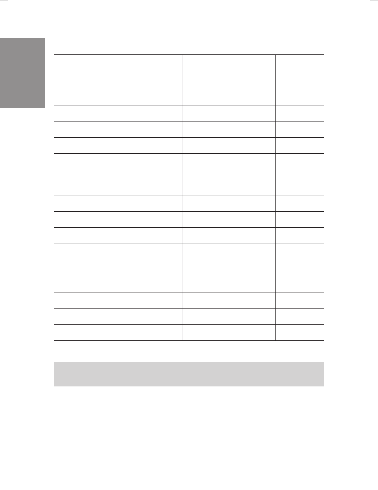
Description
Module
Slot
PABX
Connection
Internal
numbers
in the
initial
state
0
0
0
0
1*)
1
1
1
1*)
2*)
2
C46e, C48m, C88m
C88m
C88m
C46e
C48m, C88m
C46e, C48m, C88m
C48m, C88m
C48m, C88m
C48m, C88m
C46e, C48m, C88m
C46e, C48m, C88m
C48m, C88m
ISDN connection 1
ISDN connection 2
ISDN connection 3
6 Analog connections
8 Analog connections
4 Analog connections
ISDN connection 1
ISDN connection 2
ISDN connection 3
ISDN connection 4
4 Analog connections
ISDN connection 1
10...19
20...29
30...39
40...45
40...47
48...51
60...64
65...69
70...74
75...79
52...55
80...84
2
2
2*)
C48m, C88m
C48m, C88m
C46e, C48m, C88m
*) Only one module of this type can be used in each of the elmeg C46e.
Numbers are skipped when the modules are only partially implemented.
ISDN connection 2
ISDN connection 3
ISDN connection 4
6
85...89
90...94
95...99
Page 11

1.5 LED Functions for the PABX Systems
elmeg C48m and elmeg C88m
Two function indicator LEDs are located on the back of the cover (Installation
Instructions, Figure 1) of the PABX. They are located on the right side under
the cover and are visible from the outside. There are no LEDs on the elmeg
C46e PABX.
Green LED lights up: PABX in operation.
Green LED off: Hardware error.
Red LED lights up: Error indicators.
Both LEDs light up: Runup phase (initialization)
after switch-on.
Both LEDs off: Hardware reset or no
power supply to the PABX.
Green LED flashes: An internal ISDN connection is overloaded.
The Intelligent Power Management system
will quickly deactivate the ISDN connection.
Description
When the PABX is switched on, all the LEDs will light up for around 6...10
seconds. After this, the red LED will go out when the system is in operation.
The green LED indicates correct operation.
7
Page 12

1.6 Symbols, Dial tones and calling cycles
Please note: Some terminals may not produce the same dial tones, calling
cycles and operating procedures.
Description
1.6.1 Symbols used
b Thissymbolpromptsyoutoliftupthereceiverofyourphone.
g Thissymbolindicatesthecurrentcallstatus.Here:youhavelif-
tedupthereceiverofyourphone.
a Thissymbolpromptsyourtohangupthereceiverofyourpho-
neorthetelephoneisidle.
l This signal indicates signaling ata certain terminal, e.g. your
telephoneisringing.
t Thissymbolpromptsyoutodialanumber.
1x0,
Oneofthesesymbolsprompts you to select a certaindigitor
character.
*,#
=x),
Oneofthesesymbolsprompts you to select a certaindigitor
character(e.g.atelephonenumber).
~
R Thissymbolpromptsyoutopresstheflashbutton(signalbut-
ton).
q Thissymbolindicatesthatanacknowledgementsignalcanbe
heardinthereceiver.
d Thissymbolindicatesaconferencecall.
ISDN
a/b
C/CS
CS100
Thissymbolindicates:Theavailablefeaturescanbeusedwith
ISDNterminals.
Thissymbolindicates:Theavailablefeaturescanbeusedwith
analogtwo-wire terminals(a/bterminals).
Thissymbolindicates:thisfeaturecanbeusedwiththespecial
functionsofthesystemtelephoneCS1 00,C90andC100.
Thissymbolindicates:thisfeaturecanbeusedwiththespecial
functionsofthesystemtelephoneCS100.
8
Page 13

1.6.2 Dial tones a/b
The following dial tones describe signaling for the PABX system when
telephones are used.
//////////////////////////////////////////
Internal dial tone (440 Hz)
Internaldial tone. After lifting the receiver of yourphone, you willhear thisdial
tone signaling that you are free to make a call. After 30 seconds this tone
changes to the busy signal. Replace the receiver and lift it up again. You will
again hear the internal dial tone.
//____//____//____//____//____//____//____
Busy signal and negative acknowledgement signal (440 Hz)
Busy signal. When you hear this signal the externalor internal subscriberyou
are calling can not be reached.
Negative acknowledgement signal. When you hear this signal the function
you have selected can not be used, or the feature has not been configured or
has been deleted.
Description
//////////________________________________
Acknowledgement signal (440 Hz)
This signal indicates that your entry has been accepted.
Time intervals of the signals
/////_____/////_____/////_____/////_____/////
0,5s 1s 1,5s 2s 2,5s 3s 3,5s 4s
//////////______________________________///
9
Page 14

Internal ringing signal (440 Hz)
This signal indicates that the telephone is ringing at the party being called
(external or internal).
Description
//___//___//________//___//___//________//_
Special dial tone (both 440 Hz and 500 Hz)
This signal indicates, for example, that call rerouting is activated for your
telephone.
///////////////////////////////////////////
External dial tone (425 Hz)
A continuous tone you hear when you have seized the external ISDN connec-
tion.
/__/_______________________________/__/____
Call waiting signal (440 Hz)
Call waiting signal (only for a/b terminals). When you hear this signal during a
call with another party it indicates that an external caller is calling you. The call
waiting signal lasts a maximum of 30 seconds.
Time intervals of the signals
/////_____/////_____/////_____/////_____///
0,5s 1s 1,5s 2s 2,5s 3s 3,5s 4s
10
Page 15

1.6.3 Calling cycles a/b
Thefollowingillustrationsareintended toshowtheduration ofthecalling cycles.
//__//_______________//__//_______________/
Internal call,Call-back, internal Return call
Internal call: You are called directly by an internal caller or by enquiry call.
Call-back:Youare calledautomaticallywhentheparty youwishto talktohangs
up the receiver of his/her phone.
Return call: You activate an enquiry call,but hang up the receiver beforedialing.
The held first call is indicated by the return call signal 3 minutes at your phone.
/////___________________/////______________
External call, external return call, call-back of the reserved ISDN connection
External call: You receive a cal from an external party.
Return call: You activate an enquiry call,but hang up the receiver beforedialing.
The held first call is indicated by the return call signal 3 minutes at your phone.
Call-back of the reserved ISDN connection: The noted busy external ISDN
connection becomes available again; this is signaled by the call-back at your
phone.
Description
//////////__________ >8s___________________//
Door phone call
Door phone call: The doorbell button of your door phone is pressed, resulting
inringingof the phones entered in the activated TFEcallmodesattheindicated
rate for about one (1) minute.
Time intervals of the cycles
/////_____/////_____/////_____/////_____/////
1s 2s 3s 4s 5s 6s 7s 8s
11
Page 16

Description
12
Page 17

2 Installation
2.1 Installation of the PABX
Please check to ensure that all items are in the package before beginning
installation.
Contents:
• 1PABX
• 1ISDNconnectioncord
• 1PCconnectioncable9/9-pin (RS232)
• 1Setof operating instructions
• 1CD-ROM for setup programming under
Windows3.1,Windows95andWindowsNT
• Bagwith connector terminals
• 1Drilling template
• 3Dowels
• 3screws
2.1.1 Installation location
Your PABX has been designed for operation at ambient temperatures above
0 and below +40 °C.
Therefore, we recommend that you avoid installing your PABX in the following
locations:
• above or in frontof sources ofexcessive heat,e.g.radiators
Installation
• inplaces exposedtodirectsolar radiation
• behindcurtains
• insmall, non-ventilated rooms
• inrooms with excessive humidity
• onornearflammable
materials
• in the vicinityof high-frequency devices, such asradio trans-
mitters,radiotherapy systems, etc.
The PABX is powered via a 230 V AC utility outlet. Please ensure that the
electrical outlet (grounding outlet) for the PABX (and for additional devices
13
Page 18

Installation
where required) is installed such that it is freelyaccessible atall times and that
it is installed by a qualified electrician to prevent personal and material risks.
We recommend installing separate supply circuit for 230 V AC power to your
PABX.ThisprotectsyourPABXfromshort-circuitsthatmayoccurinother
inhouse equipment.
Also install functional grounding. For this, connect the grounding terminal FE
to ”Ground”. Metallically bright partsof water orheating linescan beused here
as ”ground”. Ensure that these lines are continuously conductive and that they
are connected to the grounding circuit connector of your house service
connection.
We recommend installing our fine overload protection module (FSM) for overvoltage protection of your PABX which can sometimes occur during thunderstorms.
The distance from the PABX system and the 230 VAC outlet and the ISDN
connection should not be more than 1.3 meters due to the length of the
connecting lines.
2.1.2 Wall-mounting the PABX
•
•
DonotinstallyourPABX during a thunderstorm.
• Place the drilling template on the selected mounting location
andensure thatitisperfectlyperpendicular.
• Markthe drilling points on thewall using thedrilling template.
• Ensurethatall thecontactsurfaceshavefirmcontactwiththe
wall and that there are no concealed supply cables or other
wiringatthe drilling points you haveselected.
• Drill the mounting holes at the marked positions (when using
dowels,use a 6 mm masonry drill).
• Screwthe screwssuppliedw ith thesystemintothe wallsuch
that there is a gap of about 5 mm between the head of the
screwand the wall.
• Hang the PABX on the screws by inserting the screw heads
intotherearpanelmounting holes.
• Then secure the PABX by screwing in the third screw at the
markedposition.
• Install the function ground.
14
Page 19

2.1.3 Intelligent Power Management for the
elmeg C48m and elmeg C88m
Your PABX is equipped with the Intelligent Power Management system. This
system protects the ISDN connections of the PABX against overload. The
current load is continuously monitored at each internal ISDN connection.
If too manyterminalsare connected tothe PABX, thisis indicated by aflashing
green LED (elmeg C48m and elmeg C88m). Power supply to the mounted
modules is also switched off. The PABX then attempts to reactivate the power
supply automatically after a set time. If, for some reason, the cause for the
overload is not eliminated (e.g. removal of a terminal), the ISDN connection
concernedisdeactivated.ThedeactivatedISDNconnectionisre-activatedonly
on a reset of the PABX and after elimination of the overload. Please contact
your dealer if the same ISDN connection continues to be deactivated.
Installation
15
Page 20
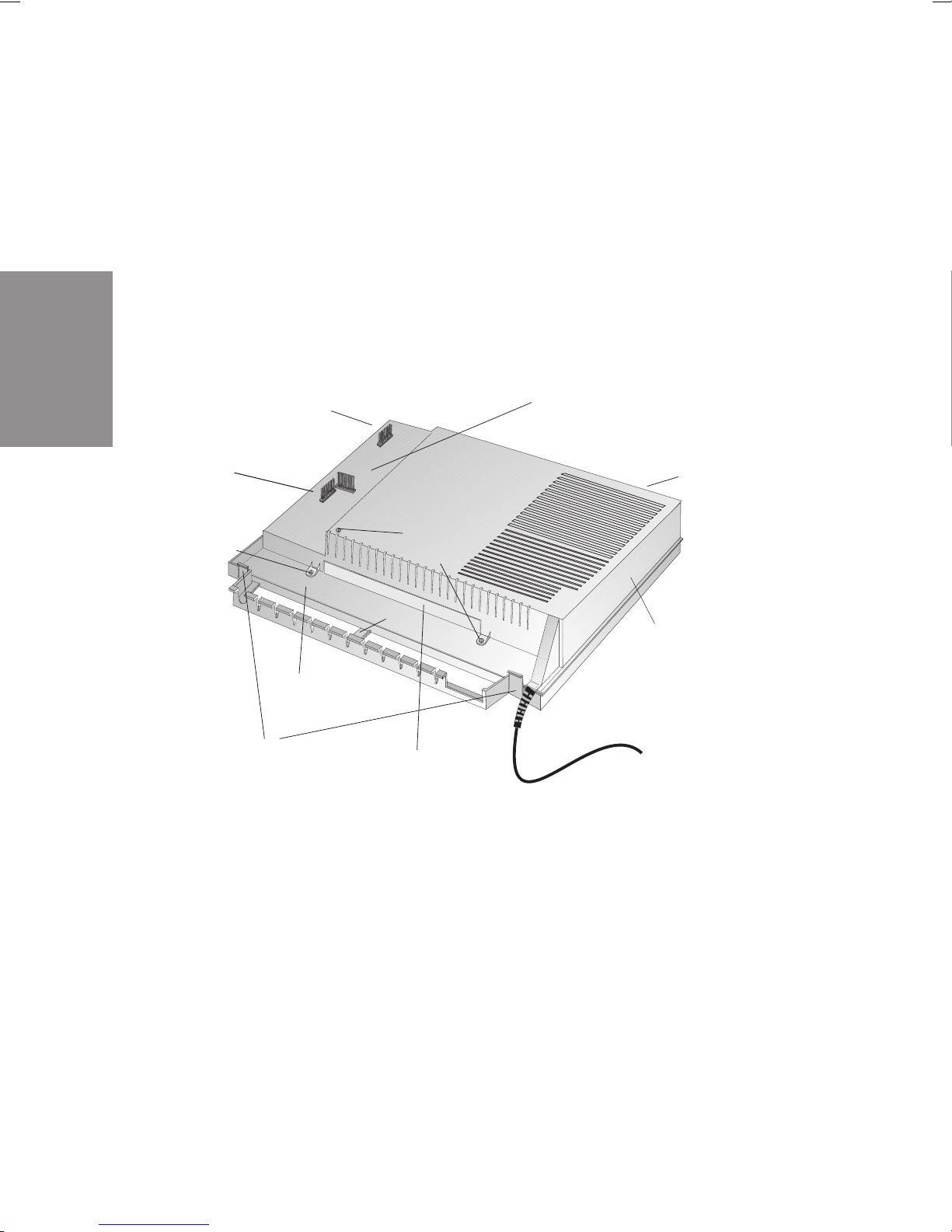
2.1.4 Opening and closing of the PABX
)
Unplug the connector plug before opening the PABX.
To open the PABX, press in on the two catches and lift the cover at the front
until it comes free. It can then be easily lifted off to access the cable terminal
bay below.
To close the PABX,place the lockingpins (backof the cover) intothe openings
in the enclosure of the PABX. Press down on the cover at the front until it
catches.
Installation
Slot for TFE 1 module
Slot for TFE 2 module
(elmeg C48m and elm eg
C88m) or NSP
module
Fixing screw s
Term inal b ay
Catches
Fixing
screws
Screws for modules
Slot for modules
Opening for TFE/NSP module
LEDs (elmeg C48m
and elmeg C88m only
Inner cover (elmeg C 48 m
and elmeg C88m only)
Fig. 1: PABX opened (in the example here: elmeg C48m/ elmeg C88m)
16
Page 21
2.2 Connections
Before installing your PABX at an ISDN connection, you must first decide what
type of connection (multipoint or point-to-point) you wish to configure as your
ISDN connection. This connection mustbe applied for at your network s ervice
providerand thenconfiguredin the PABX as describedinthesectionProgramming.
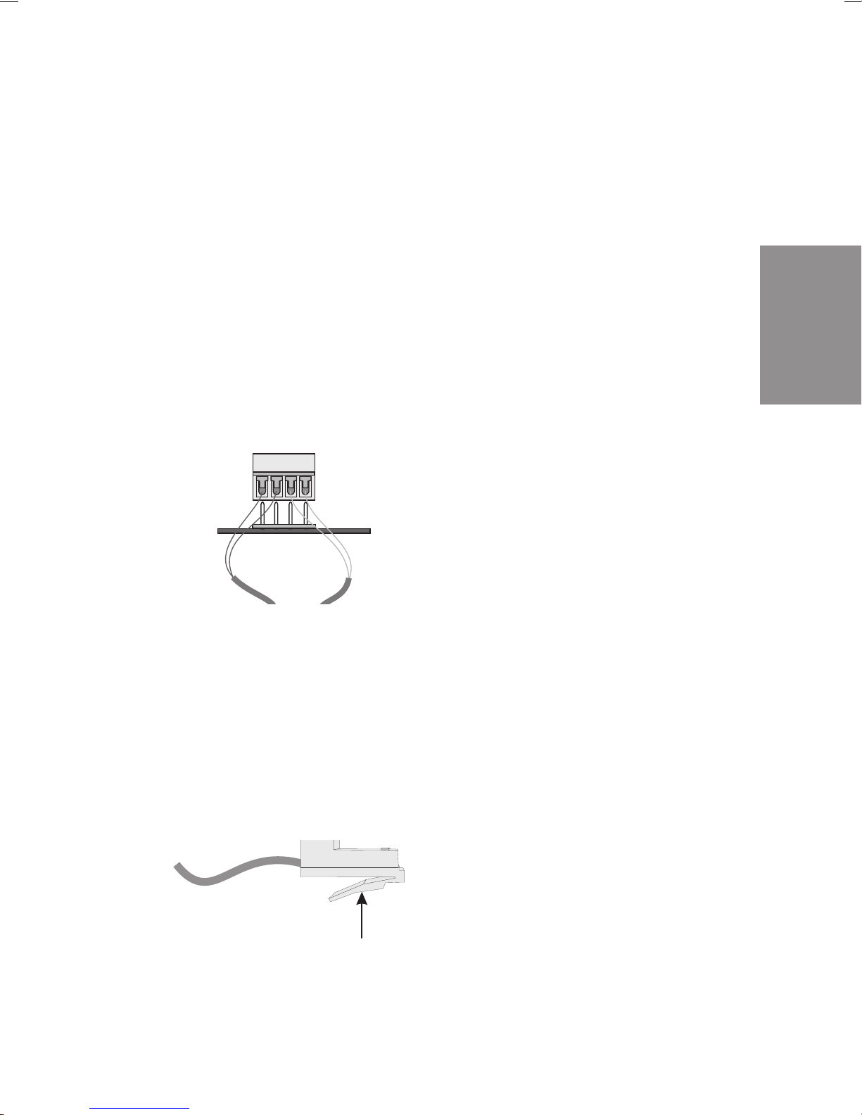
2.2.1 Terminals
The terminals can be removed from the soldered pins on the printed circuit
board (pcb). This allows you, for example, to switch user connections without
disconnecting the cables. In the as-delivered state of the PABX, the terminals
arenotconnected;theyareincludedinaseparatebag. Todisconnectterminals
which are set, lift the terminal block up carefully using a small screw driver and
then remove the terminal. Ensure that you do not bend the pins.
Te rm i na l b lo c k
Pins
Installation
Fig. 2: Plugging in the terminal block
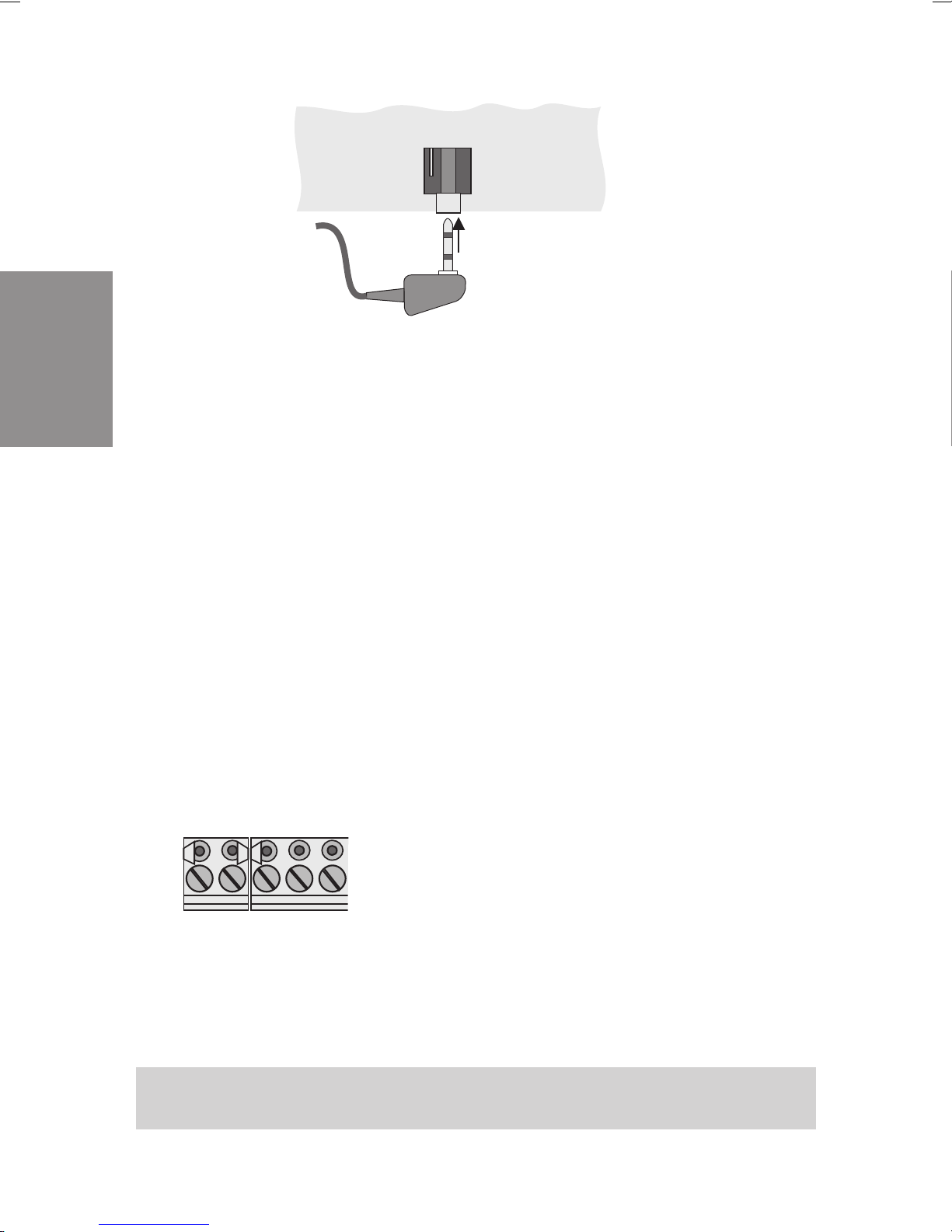
2.2.2 ISDN connectors
The ISDN connectors(Western connectors, RJ45 connectors)are lockedafter
being plugged into the ISDN jack to prevent them from being pulled out. The
lever points in the direction of the pcb after being plugged into the PABX. To
unlock these connections (Figure 3) press on the small lever on the ISDN
connector while pulling the ISDN connector out.
Lever
Fig. 3: ISDN connector
17
Page 22
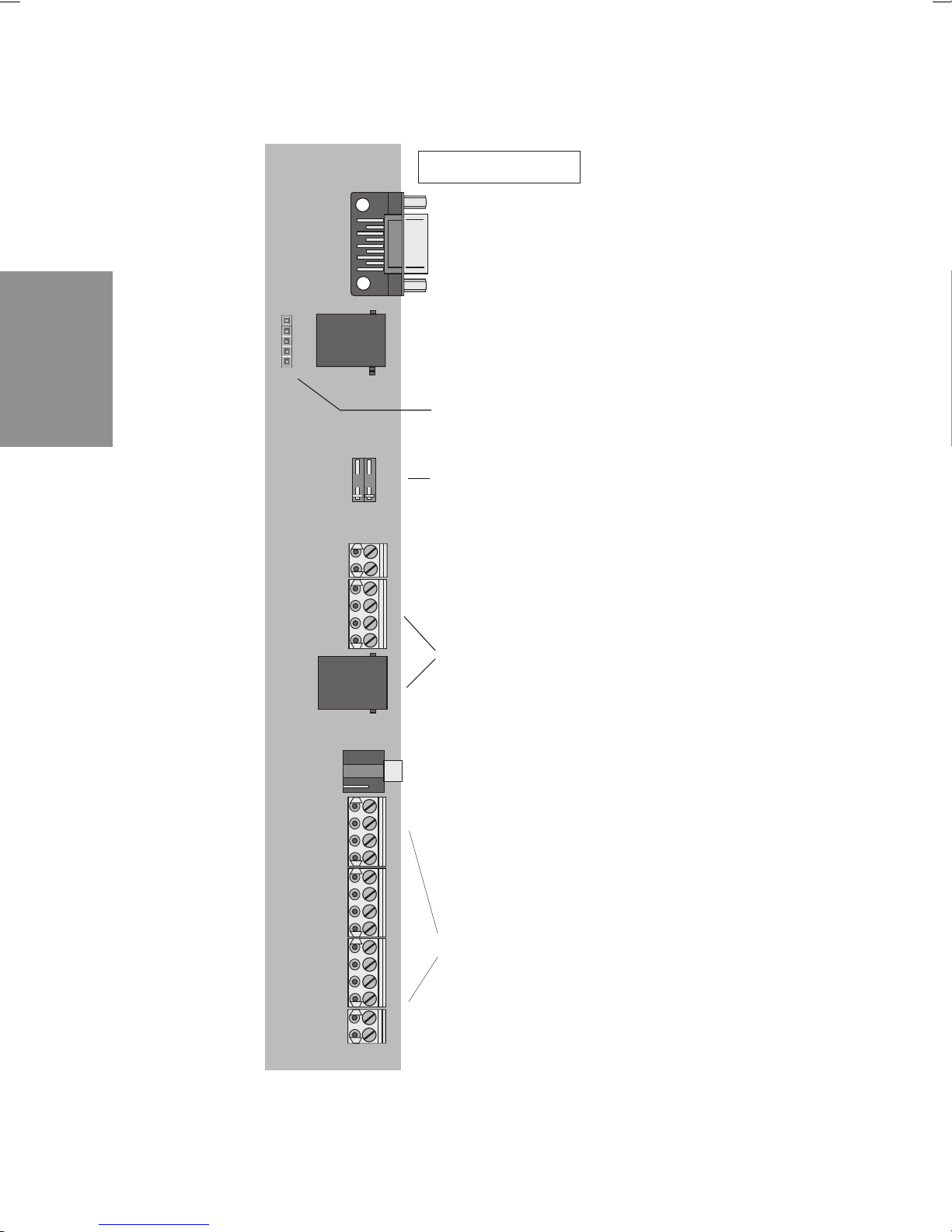
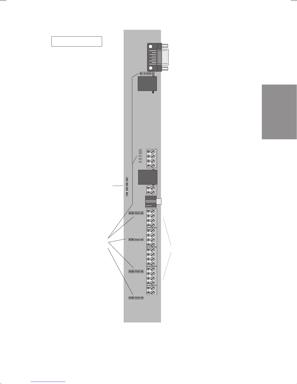
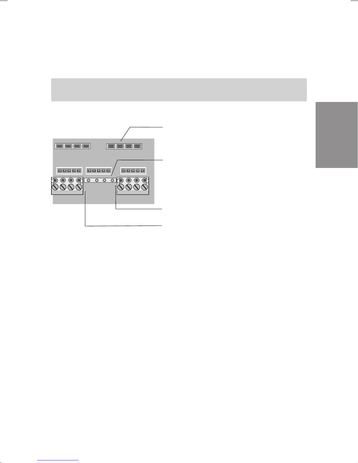
2.2.3 Connection elements of the cable terminal bay
elmeg C46e
V24
V.24 connection
External ISDN connection 2
S0 Ext.
Installation
MOH
Socket connector for the fine overload
protection module FSM
Socket connector for
external terminators
FE
S0 Int.
Connection for functional grounding
(ground)
Internal ISDN connection 1
(Connection for NSP)
Connection for
external music on hold
Fig. 4: Cable terminal bay of the elmeg C46e
Analog connections
ab1...ab6
RWS ab1 ab2 ab3 ab4 ab5 ab6
Call a.c. voltage for
central alarm
18
Page 23
elmeg C48m
Jumper for switchover
from internal to external
ISDN connection
V24
V.24 connection
External ISDN connection 4
S04:E XT
Installation
Internal ISDN connection 1
or
External ISDN connection 1
S01:INT/EXT
Internal ISDN connection 1
(Connection for NSP)
S01:INT
Functional grounding connection
FE
(Ground)
Connection for
MOH
external music on hold
Socket connector for
the fine overload
protection module FSM
Fig. 5: Cable terminal bay of the elmeg C48m
19
Analog connection
a/b1...a/b8
Call a.c. voltage for
R W S a /b 1 a /b 2 a /b 3 a /b 4 a /b 5 a /b 6 a /b 7 a /b 8
central alarm
Page 24
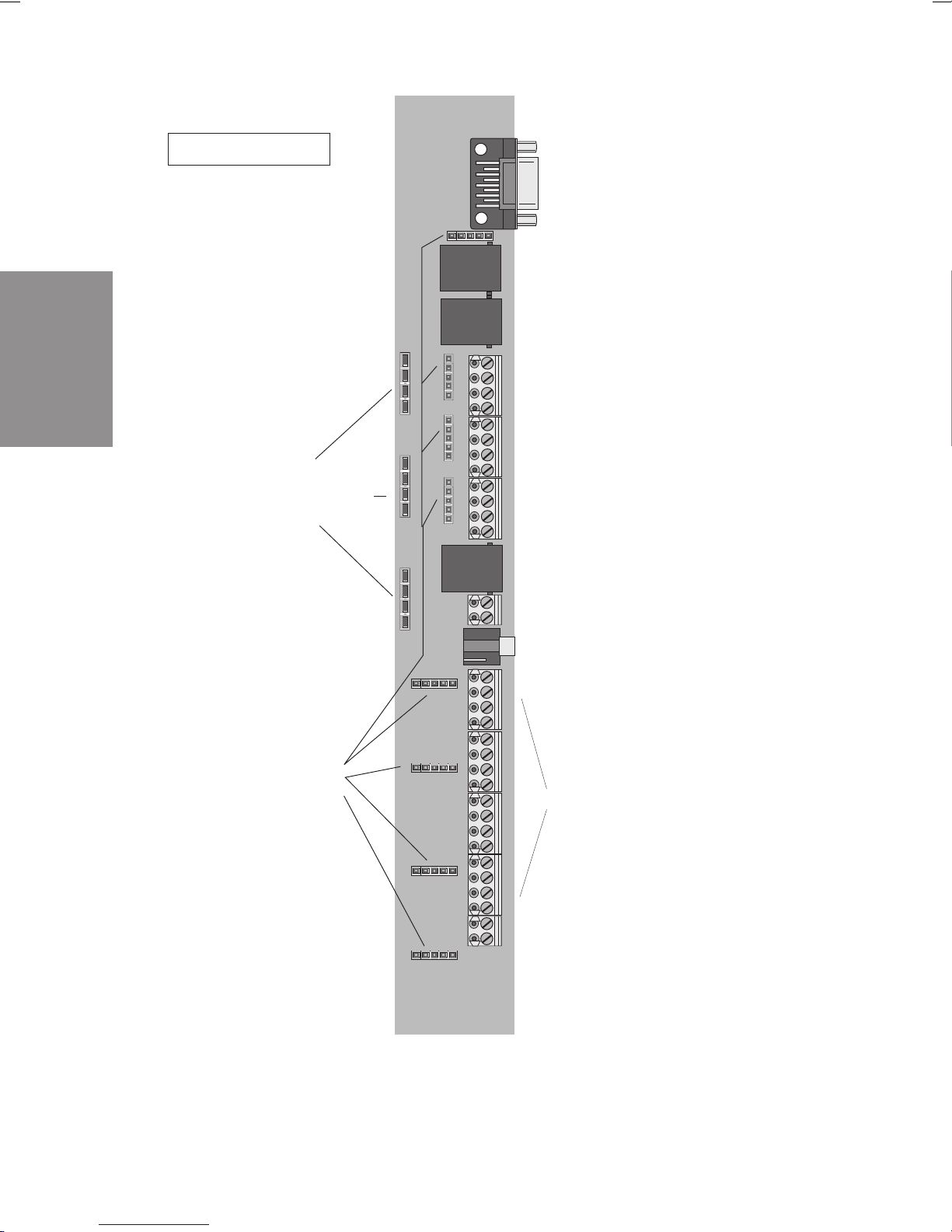
Installation
elmeg C88m
Jumpers for switchover
from internal to external
ISDN connection
V24
V.24 connection
External ISDN connection 4
S04:E XT
External ISDN connection 3
S03:E XT
Internal ISDN connection 3
or
External ISDN connection 3
S03:INT/EXT
Internal ISDN connection 2
or
External ISDN connection 2
S02:INT/EXT
Internal ISDN connection 1
or
External ISDN connection 1
S01:INT/EXT
Internal ISDN connection 1
(connection for NSP)
S01:INT
Functional grounding connection
FE
(ground)
Connection for
MOH
external music on hold
Socket connector for
the fine protection
module FSM
Fig. 6: Cable terminal bay of the elmeg C88m
20
Analog connections
a/b1...a/b8
Call a.c. voltage for
R W S a /b 1 a /b 2 a /b 3 a /b 4 a /b 5 a /b 6 a /b 7 a /b 8
central alarm
Page 25
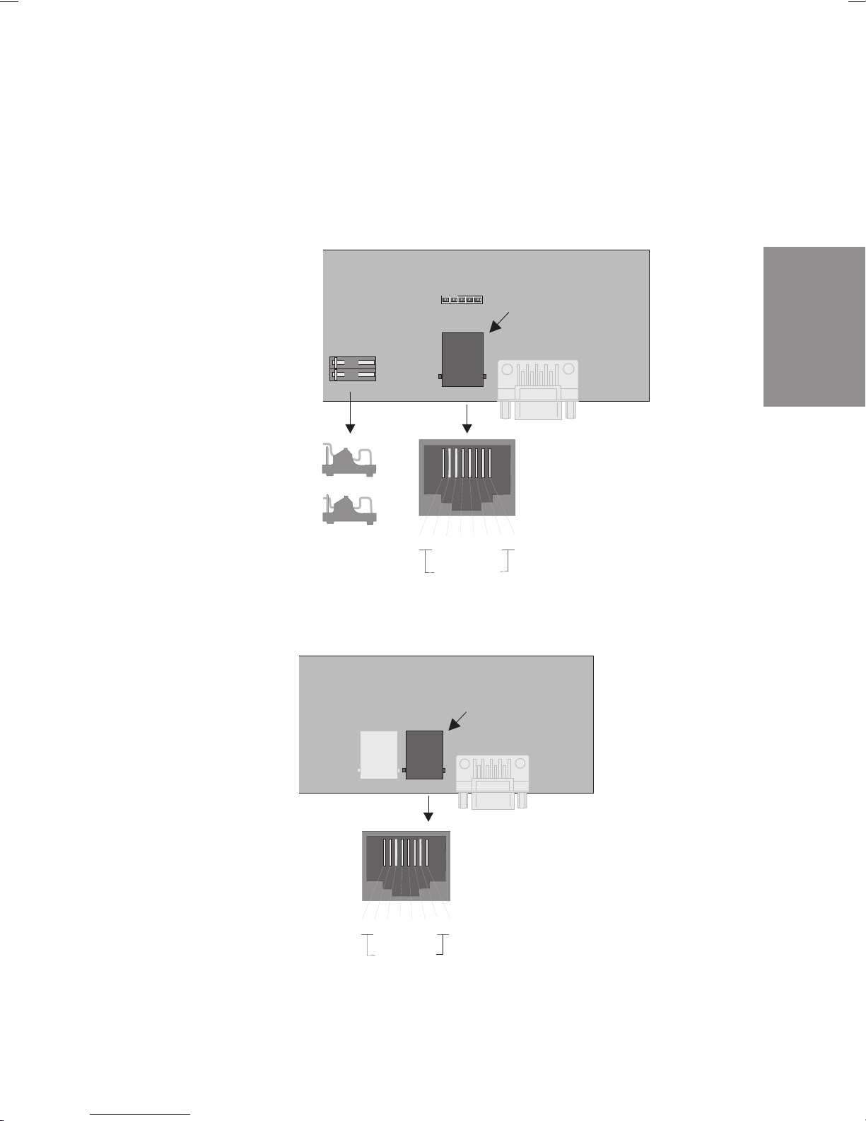
2.2.4 External ISDN connection
The external ISDN connection is routed to an 8-pin RJ45 jack (Western jack)/
The four (4) middle terminalconnections of the RJ45 jack are connected.Hard
wiring is not possible. You can also install the PABX elmeg C46e in the bus
system. For this, you can deactivate the terminators.
External ISDN connection
(S0 ex t.)
S0 Ext.
Terminators
deactivated
Terminators
activated
1234
no connected
a2a1 b1b2
5
front view
678
Fig. 7: elmeg C46e: External ISDN connection 2
Installation
Fig. 8: elmeg C48m /elmeg C88m: External ISDN connection 4
External ISDN connection 4
(S04:EXT)
S03:E XT
1234
S04:E XT
5
a1a2 b2b1
no connected
678
21
Front view
Page 26
Installation
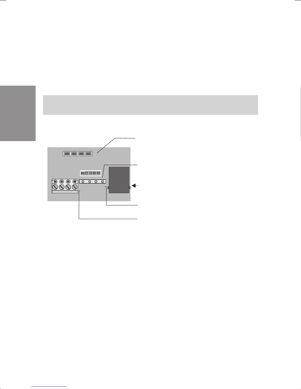
2.2.5 elmeg C88m: Internal/external ISDN connection 3
The internal ISDN connection 3 can be switched to an external ISDN connection. In the initial state this connection is set to an internal ISDN connection.
When the jumpers for the ISDN connection 3 are removed and programming
isperformedappropriately,theconnectioncanbeswitchedtoanexternalISDN
connection. The internal ISDN connection is effected at terminal block S03:
INT/EXT; the external ISDN connection at ISDN jack S03: EXT.
First remove the jumper for switchover for external connection (see Fig. 9)!
Jumper for switchover
installed : Int ernal ISD N c onne ct ion
open: external ISDN connection
ISDN t erm inal blo ck
for the internal and external ISDN connection
ISDN terminal block removed
S02:INT / EX T
a2 a1 b1 b2
a1 a2 b2 b1
S03: INT / EXT
S03:E XT
ISDN ja ck fo r ex tern al
ISDN c on nec tio n
Assignment for S03: External ISDN connection 3
Fig. 9: elmeg C88m: Internal/ external ISDN connection 3
3Assig nm ent fo r S 03: In tern al ISDN c onn ec tio n 3
22
Page 27
2.2.6 elmeg C88m: Internal/external ISDN connection 2
Figure 10 illustrates the connection circuit for the internal ISDN connection 2.
This connection is provided with fixed interfacing to the terminals.
First remove the jumper for switchover for external connection (see Fig. 10)!
Jumper for switchover
insta lled : Intern al ISDN co nnec tio n
open: external ISDN connection
ISDN term inal b loc k
for the internal and external ISDN connection
ISDN terminal block removedn
a2 a1 b1 b2
a1 a2 b2 b1
S01: INT / EX T
S02:INT / EX T
S03: INT / EX T
Assign m ent fo r S02 : Intern al ISDN co nnec tio n 2
Installation
Assignment for S02: External ISDN connection 2
Fig. 10: elmeg C88m: Internal/ external ISDN connection 2
23
Page 28
2.2.7 Internal/ external ISDN connection 1
c
t
2.2.8 Internal/external ISDN connection 1
elmeg C46e:
Can be used only as an internal ISDN connection.
When the NSP (emergency power supply) module is used, it is imperative on
the elmeg C48 m and the elmeg C88m that this connection be used as an
internal ISDN connection.
Figure 11 illustrates the connection circuit for the internal ISDN connection 1.
This connection is provided with interfacing to an ISDN jack for the internal
ISDNconnectionandfixedinterfacingtothe terminalsfor theinternalor external
ISDN connection.
Installation
First remove the jumper for switchover for external connection (see Fig. 11)!
Jumper for switchover
installed: internal ISDN connection
open: external ISDN connection
ISDN jack for
internal ISDN connection
ISDN terminal block
for internal and external ISDN conne
ISDN terminal block removed
Assignment for S01: Internal ISDN connec
Assignment for S01: External ISDN conne
FE
S01:INT
a2 a1 b1 b2
a1 a2 b2 b1
S01:INT /EXT
5
1234
a2 a1 b1 b2
nicht beschaltet
678
Fig. 11: ISDN connection 1 of the elmeg C48m and elmeg C88m (internal)
24
Page 29
2.2.9 C46e: Internal ISDN connection
ISDN jack
for internal ISDN connection
ISDN terminal block
for internal ISDN connection.
ISDN terminal block removed
a2 a1b1 b2
FE
Fig. 12: Internal ISDN connection of the elmeg C46e
S0 Int.
Installation
2.2.10 External music on hold
External music on holdcan be fedinto the PABX via a stereojack. The 3.5mm
stereo jack is not supplied with the PABX and must be purchased at a special
dealer.
elmeg C48m / C88m: When using external music on hold, the analog
connection 6 (a/b 6) can no longer be used for connecting terminals.
25
Page 30
Installation
Stereo audio jack
Stereo audio jack plug
Fig. 13: Interface for external music on hold
Technical data on the music on hold interface:
Level: max +10 dBm
Input resistance: 5000 Ohm
Electrical isolation from PABX: via capacitors
Max. voltage at input: 1.7Veff, 2,4Vs~
2.2.11 AC ringing voltage (RWS)
AC ringing voltage is required for the central alarm bell (not included in PABX
scope of supply) for the PABX. The contact assembly through which the A C
ringing voltage is switched to the central alarm bell that must be connected
externally is located on the TFE module. AC ringing voltage may not be loaded
more than 15 mA.
RWS a/b1
Fig. 14: Terminals for the ringing voltage
Only possible in the slot for TFE1!.
26
Page 31

2.2.12 Analog Connections
This figure 15 shows the terminals for the analog terminals of the PABX elmeg
C48 m and elmeg C88m. There are no a/b 7 and a/b 8 connections on the
elmeg C46e.
omitted for
elmeg C46e
!
R W S a /b 1 a /b 2 a /b 3 a /b 4 a/b 5 a /b 6 a/b 7 a/b 8
Fig. 15: Terminals a/b1...a/b8 for analog terminals
Installation
27
Page 32

Installation
2.3 Connecting the PABX to the ISDN network of the
network service provider
The following diagrams illustrate the three connecting options for the PABX to
the external ISDN connection. If there are more than one external ISDN
connections, different connecting options are available. If more than two
external ISDN connections are to be interfaced, these must be hard-wired to
the NT.
Direct ISDN connection using the ISDN connecting cord supplied with the
system at the network termination (NT) is shown in Figure 16. This connection
option is possible for PABX and multipoint connections. The switches for the
terminators in the elmeg C46e must be closed.
Fig. 16: One ISDN connection
NT
NT
Two ISDN connections
NT
Connection to an ISDN jack supplied by the network service provider downcircuit of the NT is shown in Figure 17. This connection option is possible for
PABX and multipoint connections. Observe the interfacing for the terminators
(see Fig. 18)
NT
NT
NT
Fig. 17: One ISDN connection
2
6
345
1
Two ISDN connections
28
2
6
345
2
6
345
1
1
Page 33

NT
No ter m inatin g res isto rs in
the ISDN jacks!
2
6
345
2
345
1
1
6
2
6
345
1
Fig. 18: Connection to the bus
Interfacing to an ISDN jack for a multipoint connection installed by the network
service provider is shownhere (Fig. 18).This connection option isonly possible
withmultipointconnections. The PABX mayonly be connectedin the last ISDN
jack in the bus. The 100 Ohm terminating resistors must be removed from the
last ISDN jack in the bus (see diagram), as the PABX is already equipped with
terminating resistors.
2.4 Types of connection to internal ISDN connections
Three types of connections can be implemented at the three internal ISDN
connection: the ”short passive bus”, the ”expanded passive bus” and the
”point-to-point”. When delivered from the factory, the internal ISDN connections 1 ... 3 are set for the connection ”short passive bus”.
Installation
”Short passive bus”
The”shortpassivebus”canbeupto150(wirediameter0.4mm)to200m
(wire diameter 0.6 mm) long. This setting is made during programming. Up to
12ISDN jacks may be connectedin series. You may connect up to 8 terminals,
with each internal bus supplying four terminals and the remaining four supplied
from an external source (with a dedicated power supply unit). Of these eight
terminals,two ISDN terminalscan be in operation simultaneously(e.g. withtwo
phones you can make inhouse or external calls simultaneously). The default
inhouse extension numbers for the internal ISDN connection 1 (bus 1) are
10....19, for the internal ISDN connection 2 (bus 2) 20....29 and forthe internal
ISDN connection 3 (bus 3) 30....39. These numbers can be assigned to the
29
Page 34

associated terminals by programming as required. All 100 Ohm terminating
resistors must be connected inthe lastISDN jackinstalled inthe ISDNbus (Fig.
19 ).
PAB X
Bus max. 200 m
Installation
2
345
1
6
78 1
2
345
6
78 1
2
6
345
78 1
ISD N jac ks
2
6
345
78
ISDN jac k w it h
te rm inatin g resist o rs
ISDN telep h o n e
ISDN telefax
ISDN telep h o n e
PC
Fig. 19: Short passive bus interface
2.4.1 ”Expanded passive bus”
We recommend not installing more than three (3) ISDN jacks at the node. The
terminating resistors must be located at this node. A telecommunications
distributor frame like those available at most special dealerships can, for
example, be used as the node. There must be no further terminating resistors
installed in the subsequent ISDN jacks. Thewire diameter for the exampleused
here is 0.6 mm.
30
Page 35

PAB X
max. 450 m
Distributor with
te rm inating
resistors
ISDN jac ks
8
7
6
5
4
3
2
1
8
7
6
5
4
3
2
1
8
7
6
5
4
3
2
1
ISDN te lep hone
ISDN te lefa x
Installation
Fig. 20: Expanded passive bus interface
max. 50 m
PC
31
Page 36

2.4.2 ”Point-to-point”
This type of connection allows a distance of up to 1000 m between one ISDN
terminal and the PABX. This setting is made during programming. The terminating resistors must be installed in the ISDN jack. The wire diameter for the
example used here is 0.6 mm.
PAB X
max. 1,000 m
Installation
2
6
345
1
ISD N jac k w ith
te rm ina ting
resistors
ISD N te lep h o n e
78
Fig. 21: “Point-to-point” connection
2.4.3 Connecting the ISDN terminals to the internal ISDN
connection
Figure 22 shows the interfacing to RJ 45 jacks. ´The interfacing RJ 45- 8 jacks
and the designations used for these. The terminating resistors to RJ 45 jacks
shown in Figure 23. The ”point-to-point” connection corresponds to the bus
interface(RJ45)butwithonly oneISDN jackhavingterminatingresistors.Figure
24 illustrates the connection assignment for RJ 45 4...8 jacks.
32
Page 37

a1 a2 b2 b1
Term inat ing res isto rs
1
2
345
UAE/RJ45
76
8
1
2
UAE/RJ45
345
76
8
1
2
345
76
8
UAE/RJ45
Fig. 22 Connection using UAE/ RJ45 jacks for an internal ISDN connection
b1
a1
1a
2a 2b
1b
IAE
a2
b2
a2
6
345
1 2 87
UAE
b1a1
b2
Fig. 23 Terminating resistors
Installation
33
Page 38

Installation
[-]
Terminal designation
for UAE8 jac ks
Terminal designation
for UAE6 jac ks
Terminal designation
for UAE4 jac ks
a2
a1
b1
b2
S
1
S
1
2
3
4
5
6
7
8
S
1
2
3
4
5
6
ws
rt
2
sw
3
ge
4
Screen connection (where provided)
Wire c o lo rs for the installation c able
J-Y(St)Y2x2x0,6Lg
1st pait
Core designation
in the So bu s
Fig. 24: Pin assignments for UAE-/RJ45 jacks
2nd pair
34
Page 39

2.4.4 Connecting analog terminals
Analog terminals are, for example, telephones, multifunctional devices, fax
machines of Group 2/3 and answering machines which can be connected to
the conventional telephone network or to analog PABX systems. The calling
method used for these terminals can be either pulse (PD) or multifrequency
(DTMF). Only DTMFdevices equippedwith a flashbutton should beconnected
to the PABX. PD terminals can not utilize all of the features of the PABX. If you
wish to wire the analog terminal connections, this can be performed after
removing the enclosure cover. The terminals that are then visible a/b1.....a/b8
are, in the initial state, assigned to the inhouse extension numbers 40.....47.
Terminals ”a” and ”b” are then connected to the corresponding terminals.(Fig.
26).
Cable terminal
a/b1a/b
2
a/ b1... a/ b8
Installation
1
2
3
Distance between PABX
and jacks:
max. 1,600 meters with a wire diameter of0,6 mm
max. 1,000 meters with a wire diameter of 0,4 mm
Range for PABX
2x100 Ohm
6
5
4
Fig. 25: Connection of analog jacks with the elmeg C48m / C88m
Leave yourself adequate lengths of cable in the PABX as a reserve in case
changes are made.
35
Page 40

Installation
Figure 15 on page 26 shows the lugs for analog terminals.
2.4.5 RS 232 port (V.24)
The RS 232 port can be used for connecting a laptop, PC or a printer to a
serial port. Programming of the PABX via PC or laptop is performed via this
port (see Programming). This port is not electrically isolated from the PABX
ground.
All work on the RS 232 port may only be performed when the functional
ground is properly activated. Devices which are to be connected via the
RS 232 port (e.g. PABX and printers) must first be switched off and disconnected from the 230 V AC power supply before connection is made.
9-pin jack in
the PABX
Fig. 26: RS 232 connection variants
9-pin connector
for connecting to
lap to p , PC o r p rint e
r
36
Page 41

Figure 28 shows the connections between the PABX and the PC, laptop or
p
pinj
printer and adaptation between 9-pin and 25-pin connetcors.
Connecting cord (9-pin RS 232 connector)
PABX (DCE) 9-pin connector
2332465564788
Printer (DCE)
in connector
9-
7
2233445566778
8
PC/Laptop (DTE)
ack
9-
23324205766748
PC/Laptop (DTE)
25-pin jack
Fig. 27 RS 232 Connection variants
Line designations for a 9-pin connector
2=RxD 6=DSR
3=TxD 7=RTS
4=DTR 8=CTS
5 = Ground
22334657620758
5
Printer (DCE)
25-pin jack
4
Installation
Line designations for a 25-pin connector
2=TxD 6=DSR
3 = RxD 7 = Ground
4=RTS 20=DTR
5=CTS
Serial port settings:
9600 Baud 8 Data bits Parity: none 1 Stop bit
37
Page 42

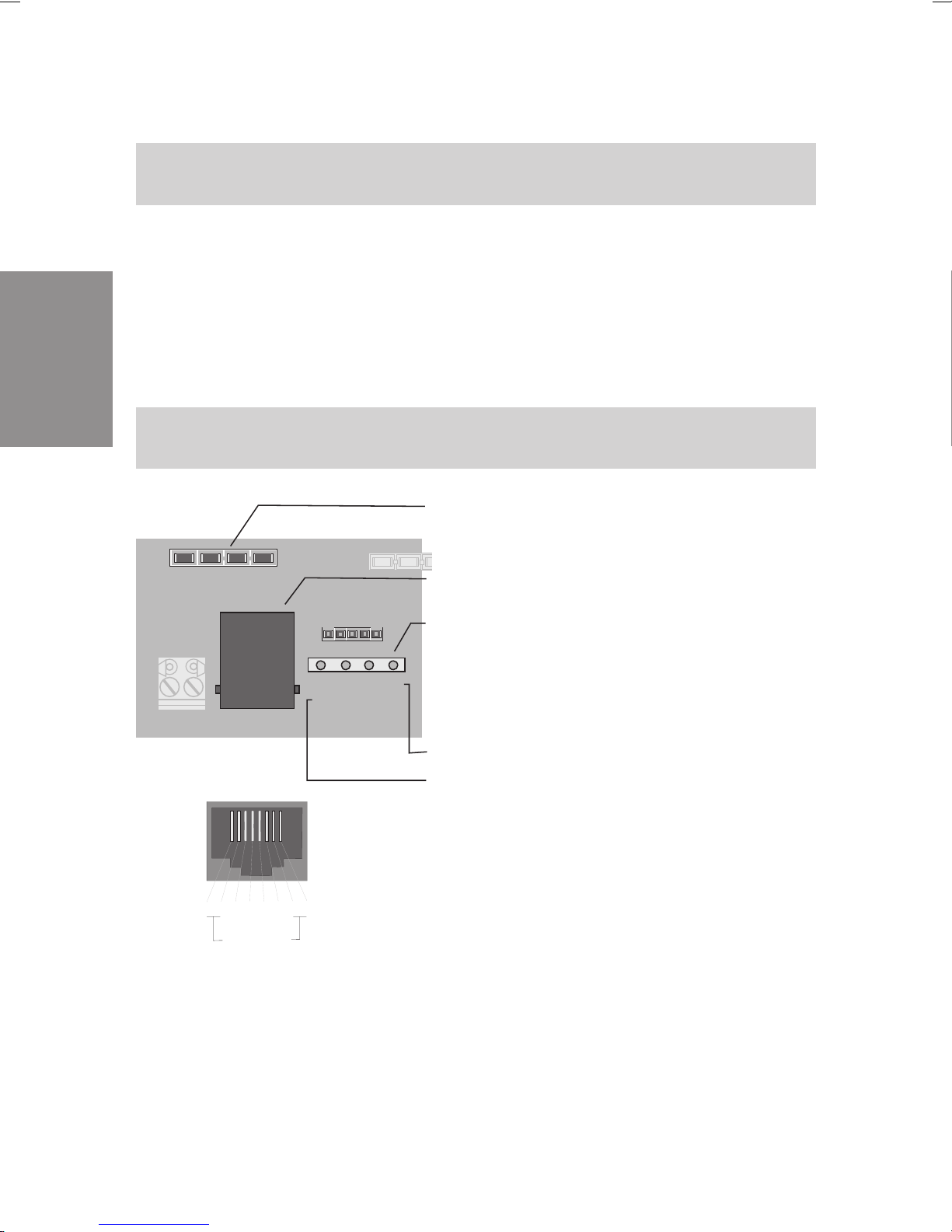
2.5 Additional modules
2.5.1 Door Intercom Module (TFE)
The TFE modules (Figure 29) are plugged into the PABX contact pins shown
on page 16 in Figure 1 and secured with two screws. P lease ensure that all
contact pins are plugged into the socket connector and that they are notbent.
Attention!
elmeg C48m / elmeg C88m: You can either install two TFEs, one NSP
(emergency power module) or one TFE and one NSP in the PABX.
Installation
elmeg C46e: You can install one TFE (TFE1) and one NSP in the PABX.
The TFE module provides you with the following additional functions:
• Interfacing of a simple door phone with speaker and micro-
phone,withoutpreamps.
• Interfacingofcallsignaling(TFEcall distribution)whichis ope-
rated in parallel tothe doorbell at theexisting ringing system
(fürjedender drei Klingeltasteristeineeigene Anrufverteilung
möglich).
• Interfacing of a central alarm bell (central bell) for direct or
alternating voltage.
• Interfacing of call signaling (TFE call distribution) using but-
tons,withoutan additional external power supply.
• Indication of door opening function by a red LED on the TFE
module.
38
Page 43

LED
Mounting holes
Socket connector
+12V
Mic
a
b
Zw1
Zw2
Ts 1
Ts 2
To1
To2
Ma1
Ma2
+24V
Me~
Me1
Me2
Me3
Me4
Lsp
Fig. 28: TFE module
2.5.2 Interfacing of a simple door phone
Figure 29 illustrates the connection of a door phone equipped with a microphone and speaker. No door intercom amplifier is required for this connection.
The bell transformer is used only for the door opener and the operating signal
lamp. The interfaceconnections at thedoor phone and belltransformer should
only be seen as examples. When the doorbell is rung, the call is signaled at all
terminals entered in the TFE call mode. If you configure an answering machine
inthecallmode,theparty atthedoor willbe ableto heartheanswering machine
message.
Technical Data for the Modules:
Speaker >8Ohm,approx.2Watts
Microphone Dynamicmicrophone,or Elektretmicrophonewithbuilt-inpre-
amp.
Installation
Doorbell Potential-freebutton
Operatingsignal
lamp
Exampleonly.Inthiscase,thislampwilllightupwhen the door
intercomis activated.Thedata forthelampdepend oftheoutputvoltageavailableatthebelltransformer.
39
Page 44

TFE module
Installation
Door phone
Bellbutton
Speaker
Microphone
Signal
lam p
Audio and
spreech paths
Mic
Lsp
a
b
+12V
LED
Zw1
Zw2
Ts1
Ts2
Door opener
To1
To2
Ma1
Ma2
+24V
Bell transformer
Me~
Me1
Me2
Me3
Me4
Door opener
Fig. 29: Interfacing of a simple door phone
2.5.3 Interfacing of a door intercom module
Figure 31 illustrates the connection of an existing door intercom module with
a door phone, door intercom amplifier and power supply to the TFE module.
Ask your dealer aboutthis. Ensurethatthe doorbell is connected potential-free,
or connect it as shown in Figure 32. When the doorbell is pressed, the call is
signaled at all of the terminals entered in the TFE call mode. If you have an
answering machine entered there, for example, a party at the door will be able
to hear the answering machine message.
40
Page 45

Bell button
Baugruppe TFE
Hör und
Sprechweg
Lsp
Po ten tialfreie K onta kte
Mic
a
b
+12V
Türöffner
TFE
Zw1
Zw2
Ts1
Ts2
To1
To2
Ma1
Ma2
+24V
Me~
Me1
Me2
Me3
Me4
Speaker
Microphone
Door phone
Door phone amplifier
Door opener
Fig. 30: Interfacing a door intercom
12 V~ power supply (internal from the
door intercom amplifier, or from an external
bell transformer)
230 V~ power supply
Installation
41
Page 46

Installation
2.5.4 Interfacing of call signaling at the doorbell
system
Figure 32 shows the connection of the TFE module to an existing doorbell
system. When the doorbell is rung, the call is signaled at all terminals entered
in the TFE call mode. You can connect up to three (3) doorbell buttons and
assignaTFEcallmodeto eachbutton.In thismanner,whenthe doorbellbutton
is pressed, onlythe phones assigned to that buttonwill ring. If thereare several
doorbell buttons, the button pressed last will be signaled. Signaling of the
button pressed first is terminated.
TFE module
Door bell
~
Fig. 31: Doorbell system
Bell transformer
Bell ring in g butto n
42
Page 47

2.5.5 Interfacing of a central alarm bell
The central alarmbell is connectedwhen anexternal call via the switchablecall
mode is present at the PABX. A central alarm bell (loud tone bell) installed in a
factoryshop or outside enablesthecallto be heardatthese places.Interfacing:
Figure 33 shows an AC alarm bell supplied from the PABX. When a DC alarm
bell is connected, use an external power supply. An external power supply
systemvia the bell transformer is thenconnected instead of powersupply from
the PABX.
B ell trans form er
230V ~
Operating voltage for
central alarm bell
orr
PAB X
RWS
TFE module
Poten t ial-free co nta c t fo r
activating the central alarm bell
Mic
a
+12V
b
~
Installation
Zw1
Zw2
Ts 1
Ts 2
Fig. 32: Central alarm bell
Only possible in slot for TFE1.
Central alarm bell
43
Page 48

2.5.6 Interfacing of call signaling at terminals using buttons
If you wish to signal a call at the terminals entered in the TFE call mode by
pressing a button, you can use the connection shown in Figure 34.
TFE module
Installation
+12V
Mic
Lsp
Fig. 33: Bell ringing button
Zw1
a
Zw2
b
Ts 1
Ts 2
To 1
To 2
Ma1
Ma2
+24V
Me~
Me1
Me2
Me3
Me4
B ell rin gin g b u t to n 1
B ell rin gin g b u t to n 2
B ell rin gin g b u t to n 3
44
Page 49

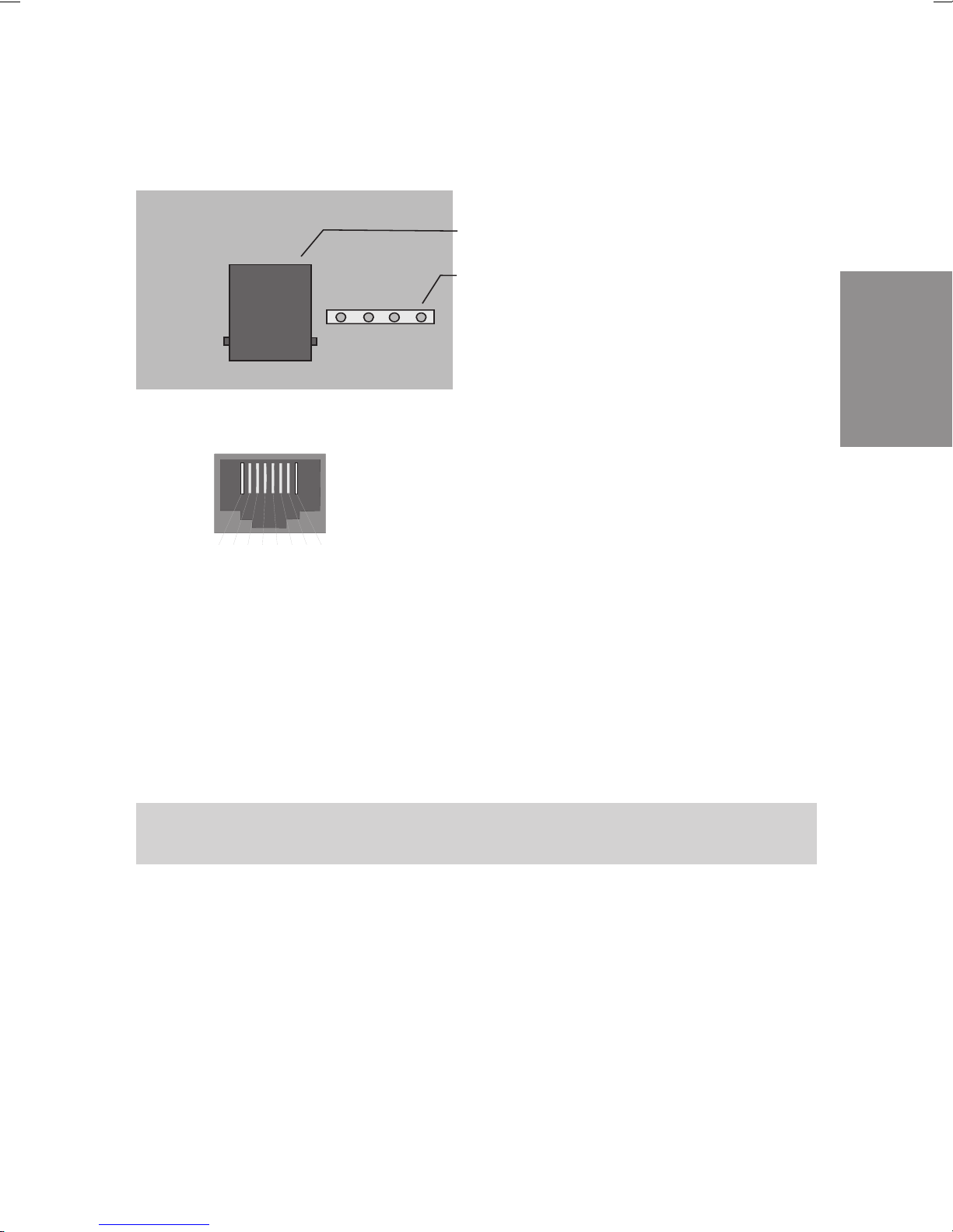
2.5.7 Emergency Power Module (NSP)
The emergency power module permits continued use of the PABX to make
calls on loss of the 230 V AC power supply. The terminal with which you can
make phone calls on loss of powermust also beequipped with an”emergency
power” function.
Attention! you can install only one NSP in the PABX.
The NSP (emergency power supply) module (Figure 35) is plugged into the
opening of the PABX marked on page 16 in Figure 1. Ensure that all of the
contact pins are plugged into the socket connector and that they are notbent.
Socket connector
Installation
Mounting holes
a1 a2 b2 b1
S0-TLN1 IN
S0-TLN1 OUT
ISDN EXT IN ISD N EXT O UT
Fig. 34: Emergency power module
The external ISDN connection and the internal ISDN connection 1 (S01:INT
with the elmeg C48m / elmeg C88m or S0 Int with the elmeg C46e) for
emergencypowersupplyareconnectedviatheNSP(seeFigure36).Interfacing
of the external and internalISDN connections is effected using the connecting
cables supplied with the system.
45
Page 50

Installation
a1 a2 b2 b1
S0-TLN1 IN
EXT OU T
ISDN EXT IN ISDN EXT O UTS0-TLN1 OUT
Fig. 35:
Co nnec ting c a b le
Co nnec ting c a b le
ISDN c o nnec ting c o rd
6
5
4
3
2
1
6
5
4
3
2
1
Internal
ISDN b us
To cable terminal
bay
"IS01: INT"
Netw ork
termination
(N T)
To cable terminal
bay for the
PABX
S04: EXT
or
S03: EXT
Block diagram, emergency power module (NSP) (in this example
here: elmeg C48m / elmeg C88m)
46
Page 51

2.6 Modules
ThePABX can be expanded using modules. Two modulescan be installedand
run in the PABX. The PABX is readily configured for the following modules:
• Module4a/bwithconnections 1...4.
• Module1/1S0 with connection 4.
• Module 4/1 S0 with connections 1...4 (elmeg C48m and
elmegC88m only).
• Module 2/1 S0 with connections 3...4 (elmeg C48m and
elmegC88m only).
The modules have already been included in programming for the PABX. If a
module is installed prior to initialcommissioning, the numbers areautomatically
assigned to the connections. The corresponding module numbers can be
found in the tables of the programming instructions.
2.6.1 Module slots
There are three different kinds of slots in the PABX:
• Slot0 = Motherboardfor thePABX.
• Slots1and2=Module slots.
These designations (0, 1 and 2) are also used for programming the PABX.
2.6.2 Installation of the modules
•
Unplugthe 230VAC plug.Disconnectthe PABXfrom allana-
•
log,TFEand ISDNconnections.
Installation
• To install the modules, you must remove the inner cover of
the PABX. It is secured by two screws - one at the lower
right-handside,andoneatthetopleft-handside(Page 16).
• Take the post connectors out of the enclosed package and
mount these at the location providedfor them inthe motherboard.
• AsshowninFigure37 mountthemoduleonthepostcon-
nectors.
• Usingthescrewsintheenclosedpackage,screwthemodule
securelytotheframegroundbar.
47
Page 52

• Connectthemotherboardto themoduleusingtheflatribbon
cable connector supplied with the system (the locking pins
onthe connectormustpointtowards thefront).
• Replacethe inner cover
Installation
Post
connecotrs
Tra ns form er
Ribbon cable
connector
M od ule 2
Catches
Ribbon cable
connector
M od ule 1
M od ule 0
(motherboard)
Fixing
screws
Fixing
screws
Grounding bar
V24
S04:EXT
S03:EXT
S03:INT/EXT
S02:INT/EXT
S01:INT/EXT
S01:INT
FE
MOH
a/b 8
a/b 7
a/b 6
a/b 5
a/b 4
a/b 3
a/b 2
a/b 1
RWS
Fig. 36: Module slots. In this example here: elmeg C88m
48
Page 53

2.6.3 Module 4 a/b
The 4 a/b module contains 4 analog connections. Connection and programming are performed the same as for the analog connections for the motherboard. In der elmeg C46e darf nur ein Modul eingesetzt werden.
a/b 1 a/b 2 a/b 3 a/b 4
Fig. 37: Module 4 a/b
Installation
2.6.4 Module 1/1 S0
The 1/1S0 module contains an S0 port that can be configured either as an
internalor as an externalISDN connection. W hen shippedfrom thefactory, the
switchover jumper is mounted,i.e. the internalISDN connectionis active.If the
ISDN is to be used as an external ISDN connection, the jumper must be
removed and this connection edited in programming. In der elmeg C46e darf
nureinModuleingesetztwerden
Jumper for switchover
inst alled : Inter n a l ISDN connec tio n
open: external ISDN connection
ISD N term inal b loc k
for the internal and external ISDN connection
ISDN terminal block rem oved
Assignment for S04: Internal ISDN connection
Assignment for S04: External ISDN connection
Fig. 38: Module 1/1S
0
S04:INT/EXT
a2 a1 b1 b2
a1 a2 b2 b1
S04:INT / EX T
49
Page 54

Installation
2.6.5 Module 2/1 S0 (elmeg C48m and elmeg C88m only)
The2/1S0module containstwoS0ports.The S03 portisdefinedas aninternal
ISDN connection. Port S04 can be configured either as an internal or as an
external ISDN connection. When shipped from the factory, the switchover
jumper is mounted, i.e. the internal ISDN port S04 is active. If the ISDN port
S04isto be used asanexternalISDNconnection, the jumpermustbe removed
and this connection edited in programming.
Jumper for switchover
installed : In t e r n al ISD N co nn e c tion
open: external ISDN connection
S04:INT/EX T
S03:INT
a2 a1 b1 b2
Assignment for S03:
Internal ISD N co nn ec t ion
Fig. 39: Module 2/1S
a2 a1 b1 b2
a1 a2 b2 b1
S04:INT / E XT
0
ISDN term inal b loc k
for the internal and external ISDN connection
ISDN terminal block removed
Assig nm ent for S0 4: In t ernal ISD N co nn ect io n
Assignment for S04: External ISDN connection
2.6.6 Module 4/1 S0 (elmeg C48m and elmeg C88m only)
The 4/1S0 module contains four S0 ports. Ports S01... S03 are defined as
internal ISDN connection. Port S04 can be configured either as an internal or
asanexternalISDNconnection.Whenshippedfromthe factory,thisswitchover
jumper is mounted, i.e. the internal ISDN port S04 is active. If the ISDN port
S04istotheusedasanexternalISDNconnection,thejumpermustberemoved
and this connection edited in programming.
50
Page 55

Jumper for switchover
installed : Internal IS D N con n ec t io n
open: external ISDN connection
S01:INT S02:INT S03:INT
a2 a1 b1 b2
Assignm ent for S01...S03:
Fig. 40: Module 4/1S
S04:INT/EX T
0
a2 a1 b1 b2
a1 a2 b2 b1
S04:INT / E XT
ISDN t erm inal b lock
for the internal and external ISDN connection
ISDN terminal block removed
Assignment for S04: Internal ISDN connection
Assignment for S04: External ISDN connection
2.6.7 Fine overload protection module (FSM)
The fine overload protection module (FSM) is provided to divert overvoltage at
analog or ISDN connecting lines (with the elmeg C46e implemented only for
theexternalISDNconnectionandthemodules).Overload protectionisrequired
for each connection that is to be protected. Any overvoltage which occurs in
the lines is diverted to the functional ground. It is imperative that you have
functional grounding installed, as shown on page 14, and that it is always
connected to provide continuous protection. The FSM module is plugged into
the slots provided for it on the motherboard and modules 1 and 2. Please do
not touch any other components on the motherboard when installing the FSM.
The FSM is of symmetrical design, so that you can choose the direction in
which it is plugged in appropriately.
Installation
Please note that the FSM module is an expendable fusible link, i.e. once a
module has been actuated it must then be replaced with a new one.
Fig. 41: Module FSM
51
Page 56

Installation
52
Page 57

3 Commissioning
3.1 Commissioning Instructions
In your agreement with your network service provider you have decided on a
multipoint connection or a point-to-point connection and have installed your
PABX in accordance with the instructions given in ”Installation of the PABX”.
Now, make all necessary connections, including the 230 V AC power supply,
for your system.
Attention!
When you activate the 230 V AC power supply it may not be interrupted
for at least 30 seconds during the initialization phase of the PABXs!
Your PABX is equipped with a changeable internal”number map”. In the initial
state the internal numbers are defined. These numbers can be changed as
required to between 00 and 99. Please ensure that internal numbers are only
used one time. The assignment code for the external ISDN connection can be
set to between 0 and 9.
Attention!
Inhouse extensions andconnection assignment code for the ISDN connec-
tion may not begin with the same number; i.e. it is not permitted to have an
internal extension starting with the number ”9” when the external ISDN
connection assignment code is also to be assigned a connection code ”9".
The required internal numbers must be programmed as MSNs (see operating instructions for the ISDN terminals: ”Entering MSNs”) in the ISDN
terminals on the internal ISDN bus.
Refer to your ISDN terminal operating manual how, and with which settings,
this feature can be implemented.
If your ISDN terminal is equipped with a call list, please note the following: The
PABX does not automatically place the ”0" for seizure of the external ISDN
connection in front of the number of the caller. Sie können diese Einstellung in
der Einrichtprogrammierung ändern.
Commissioning
53
Page 58

3.1.1 Commissioning at a point-to-point connection
Your PABX is set up for point-to-point connection when it is switched on. You
can already. make inhouse calls to analog extensions. In order that your
terminals can also be reached by external parties, you must now program the
system number.
b Liftupthereceiverofyourphone.Youwillheartheinternaldial
tone.
** Presstheasterisk(*)buttontwotimes.
q Youwillthenheartheacknowledgementsignal.
==== Enteryour4-digitpassword,e.g.0000
(intheinitial state).
12 Selectthiscode.
0 Selectthemodule(inthisexample Module 0=motherboard).
4 Selecttheconnection(inthisexamplePort4= S04:EXT).
Commissioning
t Enterthesystemnumber(ohneVorwahlundDurchwahl).
# End entry.
a Hangupthereceiver.
The terminals of your PABX can now be reached directly by external callers
and you can make external calls.
Example: Commissioning at a point-to-point connection
The network service provider has assigned you your system numbers and
number block 00.....49. These direct dial-in numbers must be dialed by an
external caller to reach a defined terminal. The number at which you can be
reached by an externalcaller is yoursystem number, e.g. 12345and thedirect
dial-in number 00...49.
54
Page 59

3.1.2 Commissioning for a point-to-multipoint connection
InstallyourPABX as described in ”Installationof the PABX”. Make all necessary
connections,includingthe230 VACpower supplyconnection,for yoursystem.
An internal MSN must be assigned to each ISDN terminal (telephone, fax Gr.
4, PC card) that is to be operated at the internal ISDN multipoint connection.
This internal MSN is one of the internal numbers 00...99. Enter the internal
number you wish to have as the MSN as described in the Operating Manual
for the ISDN terminal.
Switching over to multipoint connection
When switched on, your PABX is set up for point-to-point connection. Therefore, you must first switch it over to multipoint connection.
b Liftupthe receiver of your phone. Youwill hear the internal dial
tone.
** Presstheasterisk(*)buttontwotimes.
q Youwillthenheartheacknowledgementsignal.
==== Enteryour4-digitpassword,e.g.0000(initialstate).
q Youwillthenheartheacknowledgementsignal.
10 Selectthiscode.
0 Selectthemodule(inthisexample Module 0=motherboard).
4 Selecttheconnection(inthisexamplePort4= S04:EXT).
or
2* Selecttheconnection(in thisexampleelmegC46econnection
ISDNS0ext.)
# End entry.
q Youwillthenheartheacknowledgementsignal.
a Hangupthereceiver.
Commissioning
The PABX is now reset automatically.
55
Page 60

Youcan nowmakeinternalcallstoanalogterminals.Inorderthat yourterminals
canbe reachedspecificallybyexternal callers,you mustnowassigntheinternal
numbers for the terminal to an MSN (see Programming). You will be informed
of your MSNs when your application for this service has been approved by the
network service provider.
Example: Commissioning at a point-to-multipoint connection
You have been allotted the MSNs 12345, 12346 and 12347 by the network
service provider, for example. These MSNsmust be dialedby an external caller
in order to reach a defined extension. The number at which an external caller
can reach you is 12345, for example. If, for example, your telephone, with the
inhouse extension number 10, is to be called when this number is dialed,
proceed as follows:
b Liftupthereceiverofyourphone.Youwillheartheinternaldial
tone.
** Presstheasterisk(*)buttontwotimes.
q Youwillthenheartheacknowledgementsignal.
Commissioning
==== Enteryour4-digitpassword,e.g.0000(initial state).
q Youwillthenheartheacknowledgementsignal.
16 Selectthiscode.
0 Selectthemodule(inthisexample Module 0=motherboard).
4 Select the connection (in this example elmeg C48m / elmeg
or
2 Selecttheconnection(inthisexampleelmegC46eISDNcon-
0 SelecttheMSN/DDIindex(inthisexample=0)
t SelectthefirstMSN(inthisexample=12345)
# Pressthe#key,toendyourentry.
C88mport4= S04:EXT).
nectionS0ext.).
q Youwillthenheartheacknowledgementsignal.
17 AssigntheMSNstotheterminals.
56
Page 61

0 Selectthemodule(inthisexample Module 0=motherboard).
4 Select the connection (in this example elmeg C48m / elmeg
C88mport4= S04:EXT).
or
2 Selecttheconnection(inthisexampleelmegC46e
port2= S0Ext.).
0 SelecttheMSN/DDIindex(inthisexample=0)
10 Selecttheterminalnumber,inthisexample=10.
q Youwillthenheartheacknowledgementsignal.
a Hangupthereceiver.
The terminal withthe number 10 of yourPABX cannow be reached directly by
external callers.
3.1.3 Commissioning of ISDN PC cards with ”CAPI 1.1 interfaces”
Install the PC card in your PC. Look for the EAZ-MSN correspondence table
(EAZ map) in the operating manual for the PC card. Assign an ”internal direct
dial-in number” (inhouse extension number) to EAZ 0....9. When doing this,
observe the information provided for setup programming of the PABX in the
Section”Assigningmultiple subscribernumbers”.Start theapplicationprogram
for your PC card. Configure the defined EAZ and enter the code for seizure of
the external ISDN connection (in the initial state = ”0”).
Example:
• Your number with direct dial-in number 26 at which your PC
cardis to be reached is 12345-26.
• In a standard scenario, you have assigned this direct dial-in
numberthenumber26 in setup programming for the PABX.
Then, during configuration of the PC card you assign the direct dial-in number
(MSN) 26 to EAZ 8.
Commissioning
57
Page 62

Commissioning
58
Page 63

4 Operation
4.1 elmeg CS100 system telephones CS100
You can also use elmeg CS100 system phones with the PABX system. This
requires no special programming.The PABX willrecognize an activatedsystem
telephone automatically.
You can configure the following function keys on the elmeg CS100 system
telephone:
• distinct allocation of the external ISDN connection via the
MSN
• connectionkey(exchange key)
• linekey(internalsubscriber key)
• Day/Nightswitchover of the switchablecall modes
• teamkeys
• enter/deleteteam function
• message/messageinhibit
• Simplexintercom/intercominhibit
• Boss/secretaryfunction
The description, configuration and definition of these functions are provided in
the Operating Manual for the elmeg CS100 system telephone.
Messages can be placed through to system telephones elmeg CS100 and,
starting at software version 3, to the elmeg C90 and C100 ISDN telephones.
Simplex intercom can be implemented to elmeg CS100 system telephones
and, starting at software version 3, to elmeg C90 and C100 ISDN telephones.
4.1.1 Message
The message function allows you to set up a connection from one system
telephone to anotherone, or to ateamwith several system telephones, without
this connection having to be actively accepted.
C/CS
Operation
Messages are accepted automatically at the phones beingcalled by activating
the speaker when:
• thetelephone is idle,
59
Page 64

• themessagehas not been explicitlydeactivatedand
• thefunction”don’t disturb” has not been activated.
C/CS
If the don’t disturb function is activated at a system telephone, no messages
can be put through to this phone. You can also specifically inhibit or permit
messages using a function key or a code procedure.
Enable (permit) messages
b Lifttheheadsetofyoursystemtelephone.
Youwillheartheinternaldialtone.
*591 Selectthiscode.
q Youwillheartheacknowledgementsignal.
a Replacetheheadset.
Yoursystemtelephonecannowreceivemessages.
Inhibit messages
b Lifttheheadsetofyoursystemtelephone.
#591 Selectthiscode.
Operation
q Youwillheartheacknowledgementsignal.
a Replacetheheadset.
4.1.2 Simplex intercom
The intercom function allows you to set up a connection to another system
telephone without this connection having to be actively accepted. Intercom
calls are accepted automatically by the phone being called by activating the
”hands free calling” function when:
Youwillheartheinternaldialtone.
Nomessagescanbeputthroughtoyoursystemtelephone.
CS100
• thetelephone is idle,
• theintercomfunction has not been explicitly deactivated and
• thefunction”don’tdisturb”hasbeendeactivated.
60
Page 65

If, during an intercom call, the headset of the system telephone is lifted up, the
call is transformed into a normal call.
If an intercom connection is not ended by one of the two subscribers, this
connection is terminated automatically in the PABX after a defined time (approx. 2 minutes).
C/CS
If the don’t disturb function is activated at a system telephone, no intercom
connectionsarepossibleatthisphone.Youcanalsospecificallyinhibitorpermit
intercom calls using a function key, or a code procedure.
Enable (permit) intercom calls
b Liftuptheheadsetofyoursystemtelephone.
Youwillheartheinternaldialtone.
*590 Selectthiscode.
q Youwillheartheacknowledgementsignal.
a Replacetheheadset.
Intercomcallsarenowpossibleatyoursystemtelephone.
Inhibit intercom calls
b Liftuptheheadsetofyoursystemtelephone.
Youwillheartheinternaldialtone.
#590 Selectthiscode
q Youwillheartheacknowledgementsignal.
a Replacetheheadset.
Intercomcallsarenotpossibleatyoursystemtelephone.
Operation
61
Page 66

4.2 Internal and external connections a/b-ISDN
In the following operating sequences, onlya phone link,i.e. a callbetween two
users, is presented as an example. For analog telephones, only the functions
for multifrequency (DTMF)calling phones orDTMF terminals with aflash button
are explained.
4.2.1 Taking a call
l Yourtelephonerings.
b Liftupthereceiverofyourphone.
g Conductyourcall.
a Hangupthereceivertoendthecall.
4.2.2 Accepting a call in the group
A call is signalled at a telephone in your group. You would like to accept this
call at your own phone.
b Liftupthereceiverofyourphone.
Operation
*0 Dialthiscode.
a/b-ISDN
a/b-ISDN
Youwillheartheinternaldialtone.
g Youcanthenconductthecallfromyourphone.
4.2.3 Inhouse connections
All calls, fax transmissions or data exchange transmissions which are made
between the internal analog and ISDN terminals are designated as ”internal”
(inhouse) connections. If a connection is made between the internal terminals
and the terminals connected to the external ISDN multipoint connection, this
represents an external connection for which you will be charged.
a/b-ISDN
62
Page 67

4.2.4 Inhouse calling a/b-ISDN
You would like to make an inhouse connection with another PABX subscriber.
b Liftupthereceiverofyourphone.
Youwillheartheinternaldialtone.
t Dialthenumberoftheinhousesubscriberyouwishtocall.
Youthenheartheringingtone.Theinhousesubscriberis being
called.
Thecalledsubscriberanswershis/herphone.
g Conductyourcall.
a Hangupthereceiverofyourphonetoendtheinhousecall,or
the inhouse partyyou are takingto hangs upthereceiver. You
then hear the busy signal. Hangupyour receiver. This cancels
theinhouseconnection.
4.2.5 External connections
You can establish two external connection simultaneously via the two B
channels of an ISDN connection. These connections can also exist simultaneously with two different parties.
This allows you, for example, to call an external business partner while you
simultaneously transmit data from your PC to another business partner.
An external caller who has dialed a non-existing internal direct dial-in number
when the PABX is set up for a point-to-point connection, is signaled at the
telephones in the switchable call modes. At the same time, the central alarm
bell can be activated.
When you make an external call via your PABX, the PABX automatically
transmits the serviceidentification character thathas been programmedfor the
analog connection or in the ISDN terminal.
Please note: ISDN terminals linked to multipoint connection and the internal
ISDNbusmaynot always havethesame dialtones,callingcycles andoperating
procedures as the PABX analog terminals. This has nothing to do with your
PABX, but results because of the differing ISDN terminals.
a/b-ISDN
Operation
63
Page 68

4.2.6 External calls a/b-ISDN
You wish to establish an external connection with an external subscriber, or
with a subscriber with a multipoint connection.
b Liftupthereceiverofyourphone.Youwillheartheinternaldial
tone.
9
or
IfyouwishtocallviaanyavailableexternalISDNconnection,
dial9
or*80.
*80
ForspecificselectionofanexternalISDNconnection:
*8 dialthiscode.
Select the external ISDN connectionthrough which youwish
tocall:
1 ISDNconnection1.
2 ISDNconnection2.
3 ISDNconnection3.
4 ISDNconnection4.
5 ISDNconnection5.
Operation
t Dialthenumberyouwishtocall.
g Conductyourexternalcall.
a Endthecallbyhangingupyourreceiver.
6 ISDNconnection6.
Youwillthenheartheexternaldialtone.
If,afterdialing9 or*80 to *86 ,youhearabusysignal,
eitheryourtelephonedoesnothavethecorrectauthorization,
ortheexternalISDNconnectionisbusy.
Youthenheartheringingtone.
Theexternalsubscriberisbeingcalled.
Thecalledpartyliftsthereceiverofhis/herphone.
64
Page 69

4.2.7 Block calling (initializing call) a/b
With the aid of block calling it is possible to first input the number completely
at the terminal and to store it temporarily in the PABX. Then, you can initiate
calling of the complete number to the exchange. With some network service
providers block calling is essential to permit specific direct dialing to a certain
terminal. This feature is described in the operating instructions for ISDN
terminals. Block calling is also possible for inhouse calling.
b Liftupthe receiver of your phone. Youwill hear the internal dial
tone.
*55 Dialthecode.
9
or
Ifyouwish tocallviaanyavailableexternalISDNconnection,
dial9
or*80.
*80
ForspecificselectionofanexternalISDNconnection.
*8 Dialthiscode.
SelecttheexternalISDNconnectionthroughwhichyouwishto
call:
1ISDNconnection1.
2ISDNconnection2.
3ISDNconnection3.
4ISDNconnection4.
5ISDNconnection5.
Operation
6ISDNconnection6.
t Dialthenumberyouwishtocall.
# Beginyourcallbypressingthebutton#.
Onlynowisyourcallsenttotheexchange.
Youthenheartheringingtone.
Theexternalsubscriberisbeingcalled.
Thecalledpartyliftsthereceiverofhis/herphone.
g Conductyourexternalcall.
65
Page 70

a Endthecallbyhangingupyourreceiver.
4.2.8 Routing discrimination
This feature can only be used when there are two or more external ISDN
connections available. During programming of the PABXyou candefine which
externalISDN connection you seize from one or more set terminals.Themakes
it possible, for example, to have the PABX used by two companies, or to keep
an ”executive line” free.
Rate charging can then be specifically assigned to the ”companies” and the
terminals. Routing discrimination can notbe disabled by ”specific seizure of an
external ISDN connection”.
4.2.9 Automatic exchange line acquisition of
The PABX allows individual users to automatically or manually activate the
seizure of an external ISDN connection using a defined procedure. When this
feature is activated, you are switched immediately to the external ISDN connection after picking up your receiver; you will then hear the external dial tone.
You can then immediately begin your external call. If you wish to make an
inhouse call, lift up your receiver and press the button *; after this, you can
make an inhouse call. If you wish to make an inhouse call and hear the busy
signal after lifting your receiver (external ISDN connections are busy), first
Operation
deactivate the feature ”automatic exchange .....”, replace the receiver and lift
it up again. You will then hear the internal dial tone.
a/b-ISDN
a/b-ISDN
an external ISDN connection
Activating automatic seizure
b Liftupthereceiverofyourphone.Youwillheartheinternaldial
tone.
*56 Dialthec ode.
q Youwillthenheartheacknowledgementsignal.
a replacethereceiver;thefeaturehasbeenactivated.
66
Page 71

Inhouse calling
b Liftupthereceiverofyourphone.Youthenheartheexternaldial
tone.
* Select*.
Youwillheartheinternaldialtone.
t Youcannowmakeinhousecalls.
Deactivating automatic seizure
b Liftupthereceiverofyourphone.Youthenheartheexternaldial
toneorthebusysignal.
*#56 Selectthiscode.
q Youwillthenheartheacknowledgementsignalfollowedbythe
internaldialtone.
Deactivating automatic seizure for busy, external ISDN connection
b Liftuptheheadsetofyourtelephone.Youhearthebusysignal.
#56 Selectthiscode.
q Youwillthenheartheacknowledgementsignal,followedbythe
busysignalagain.
a Replaceyourheadset;thisfeatureisnowactivated.
Operation
67
Page 72

4.3 Call-by-Call Management
4.3.1 Call-by-Call
Usually, you are connected to your network service provider when you lift up
the headset of your phone and dial 0. The feature ”Call-by-call” permits you to
make calls viaa different providerwhich you can set by programming. Forthis,
youcan enter up to10 codesfor any desiredproviders when programming the
PABX. The PABX will always first dial the number of the provider that you have
entered first in the list. If a provider is busy, the PABX automatically dials the
number for the next one in the list. If all of the providers in the list are busy, the
connection is set up via your standard network service provider.
You can define 50 numbers (unit numbers) in the PABX which are not subject
to the call-by-call function. When you dial a number which begins with one of
the unit numbers entered in the list, this number id dialed directly, without the
code of the provider being added.
Examples for unit numbers which should not be subject to the call-by-call
function:
1, 2, 3, ...9 Local numbers
010 Number for other network service providers
0130, 0180, 0190 Service numbers in Germany
0700, 0800, 0900 Service numbers in Germany
0800 Service numbers in Austria
Operation
0800, 0900 Service numbers in Switzerland
4.4 Team call a/b-ISDN
elmeg C46e: You can configure up to 20 teams (00...19).
elmeg C48m / C88m: You can configure up to 40 teams (00...39).
This feature can be used at either multipoint or point-to-point connections or
for internal communication. In setup programming, you can assign up to eight
(8)inhousenumbers to a team.Theseteamscan thenbeassignedtothe MSNs
orthedirect dial-in numbers. Forinternalteamcalls, a team number is assigned
to a team during programming. If one of these MSNs or direct dial-in numbers
are then called by an external subscriber oder von einem internen Teilnehmer
68
Page 73

die Teamrufnummer, all assigned terminals are called. Teams are not configured as a function of the service. The switchable call modes ”Day” and ”Night”
can be configured within each team. Call rerouting to an external subscriber is
also possible within each team. Teams can not be called during an enquiry call
or call forwarding.
4.4.1 Call at a busy team subscriber
(busy on busy)
When a member of a team is conducting a call you can decide whether further
calls for this team are to be signaled or not. If the function ”busy on busy”
configured for this team, any further callers to this team will hear the busy signal.
4.4.2 Entering in/Deleting from a team (temporary)
First, permanently assign your number to one, several or all teams during
programming.
You can enter or delete yourself in the switchable call modes for a team, or for
all teams. If you are not entered, no team calls will be signaled. Entering and
deleting is effected simultaneously in the day/nightmodes. If allsubscribers are
deleted, the external call will be put through to the terminals entered in the
current service-specific call modes.
a/b-ISDN
a/b-ISDN
Entering in a team
b Liftuptheheadsetofyourtelephone.
Youwillheartheinternaldialtone.
*943 Selectthiscode.
t Dialtheteamnumber.
q Youwillheartheacknowledgementsignal.
a Replacetheheadset.
Operation
69
Page 74

Deleting from a team
b Liftuptheheadsetofyourtelephone.
Youwillheartheinternaldialtone.
#943 Selectthiscode.
t Dialtheteamnumber.
q Youwillheartheacknowledgementsignal.
a Replacetheheadset.
Entering in all teams
b Liftuptheheadsetofyourtelephone.
Youwillheartheinternaldialtone.
*943 Selectthiscode.
* Confirmyourentry.
q Youwillheartheacknowledgementsignal.
a Replacetheheadset.
Deleting from all teams
Operation
b Liftuptheheadsetofyourtelephone.
#943 Selectthiscode.
* Confirmyourentry.
q Youwillheartheacknowledgementsignal.
a Replacetheheadset.
Youwillheartheinternaldialtone.
70
Page 75

4.5 Group call a/b-ISDN
Youcanconfigure groupcallsforteams, service-specificswitchablecallmodes
and for the TFE call modes.
There are two types of group call modes, ”simultaneous” and ”linear”.
Simultaneous group call:
All assigned terminals are called simultaneously as prescribed by their service.
If a phone is busy, call waiting is effected.
Linear group call:
All assigned terminals are called simultaneously as prescribed by their service;
if, for example, a terminal is busy, the next free one is called. At each terminal
the incoming call will be signalled for approximately 15 seconds.
4.6 Forwarding a call a/b-ISDN
4.6.1 Forwarding a call with prior notice
You wish to forward a call to an inhouse or external subscriber, or forward an
external call to an inhouse subscriber and talk to the party before he/she
accepts the call.
If so programmed, the party on hold will hear music on hold.
g Youareconductingacall.
You would like to forward this call to another inhouse, or to an
externalsubscriber.
R Pressthesignalbutton.
Youwillheartheinternaldialtone.
t Dialthenumberofthedesiredsubscriber.
Youwillthenheartheringingtone.
Theotheruserisbeingcalled.
Theuserliftsupthereceiver.
Operation
(If you hearthe busysignal, press thesignal buttonR againto
retrievethecall.)
71
Page 76

g Conductyourcall.
a Hangupthereceiver.
4.6.2 Connecting two external callers with one another
Please note that ISDN terminals can only carry out forwarding of external
calls to an external party via the keypad function, or using a special button.
If you connect two external callers after an enquiry call, please note:
• Duringthiscall, two B channels of your PABX are occupied.
• The call ratesare chargedthe same fornormal connections.
If you s tarted both external calls, you will be charged for the
two calls between the external parties. If you connected an
external caller after an enquiry call to another external party,
the caller will be charged for his/her call andyou will be chargedfor the call that you forwarded.
g In an enquiry call you are conductingan external call; the first
R Pressthesignalbutton.
*4 Pressthebutton* andthenthebutton4.
Operation
a Hangupyourreceiver.
4.6.3 Forwarding calls without prior notice
Call transfer without prior notice (explicit call transfer). You can forward calls
within the PABX by dialing the number of the person you wish to call and then
hanging up yourreceiver. The personyou are calling isthen calledandreceives
the call after lifting the receiver.
externalcallisplacedonhold.
You would like to connect the two external callers with one
another andwishtoendthecallyourself.
Thetwoexternalcallersarenowconnected.
a/b-ISDN
g Conductyourcall.
R Pressthesignalbutton.
Youwillheartheinternaldialtone.
72
Page 77

t Dialtheinhouseextensionnumberyouwishtocall.
Youwillheartheringingtone.
Theinhousesubscriberisbeingcalled.
r (Ifyouhearthebusysignal,pressthe
signalbuttonagaintoretrievethecallonhold.)
a Hangupyourreceiver.
Theinhousesubscriberisbeingcalled.Theinhousesubscriber
beingcalledliftsuphis/herreceiverandcontinueswiththecall.
4.6.4 Enquiry call
With the enquiry call function it is possible to interrupt an internal or external
callinorder toconductanenquirycall.Theotherpartycan nothearyourenquiry
call. When you complete your enquiry call, you can continue with your callthat
was in progress. If so programmed, the party on hold will hear music on hold.
a/b-ISDN
g Youareconductingacall.
Youwouldliketomakeanenquirycall.
R Presstheflash button foranalogtelephones.Youwillthenhear
theinternaldialtone.
t Dialthenumberoftheinhousepartyyouwishtocall.
Youwillheartheringingtone.
Theinhousesubscriberiscalledandliftsupthereceiver.
g Conductyourenquirycall.
Toendanenquirycall(specificforISDNterminal),pressthedisconnectbuttononyourISDN phone
Operation
or or
R*1 WithananalogterminaltheflashbuttonR mustbepressedfirst
and then thecode *1 dialed;the current call is then disconnectedandyouwillbereconnectedwiththef irstcaller.
g Continuewithyourcall.
73
Page 78

4.6.5 Broker’s call (operation varies with
terminal used)
The ”broker’s call” feature permits you to switch back and forth between two
inhouse subscribers, two external callers or between an inhouse and external
caller. The caller put on hold will, if so programmed, hear music on hold.
a/b-ISDN
g Youareconductingacallandwishtoconductanenquirycall.
R With analogphonespresstheflashbutton.
Please consult the operating instructions for information on
thisfunctionforISDNphones.
You will hear the internal dial tone; the first caller is placed on
hold.
t Dialthenumberofthepartyyouwishtocall.
Youwillheartheringingtone.
Theuseriscalledandliftsupthereceiver.
g Conductyourenquirycall.
R*2 With analog phones, first press the flashbutton and then dial
g Continuewithyourfirstcall.
or or
r Please consult the operating instructions for information on
Operation
g Continuewithyourcall.
a Hangupthereceivertoendthecall.
When you are switching between an inhouse party and an external caller
and hang up the receiver your call is ended and your two callers are connected with one another!
When you are switching between two external callers and hang up the receiver, the existing call is ended and the call that was placed on hold is signaled with ”return call”.
When, during a broker’s call, you press the button * and then the button4, the two external callers are connected with one another and your
call with the external callers is ended.
thecode*2 toswitchbetweenthefirstandsecondcaller.
thisfunctionforISDNphones..
74
Page 79

4.6.6 Forwarding calls ISDN
This function allows you to forward a call without having to accept the call
yourself. You can take advantage of this feature with elmeg CS100 system
telephones, or with ISDN telephones which support this function.
4.6.7 Switching a waiting subscriber
This function allows you to put several connections on hold and to switch one
of the subscribers on hold via a further connection (enquiry connection). You
can take advantage of this feature with elmeg CS100 system telephones, or
with ISDN telephones which support this function.
ISDN
4.7 Automatic call-back a/b-ISDN
4.7.1 Request automatic call-back (subscriber busy) a/b-ISDN
Asasubscriberyoucaninitiatetwoautomatic call-backs(subscriber busy) with
an analog telephone. With an ISDN phone you can initiate up to eight (8)
call-backs (subscriber busy) for each internal ISDN connection, and reserve
one external ISDN connection. You can utilize this feature at an ISDN terminal
when your ISDN terminal can dial via the keypad when busy or during a call,
orwhenthisfeatureisofferedviaasoftkey.At0:00o’clockthefeatureof
reserving anexternal ISDN connection iscleared. internal automatic call-backs
are deletedautomatically after 30 minutes. The external automatic call-back is
cleared after a time period defined by the exchange (usually after about 45
minutes). Manual deleting is also possible. An automatic call-back is not
possible from an enquiry call.
Operation
You call an inhouse or an external party. The party being called is busy (you
hear the busy signal). Dial the code *4 and hang up your receiver. When the
party you called hangs up his/her receiver, this will be signaled on your phone.
Your connection is set up via the external ISDN connection which you used to
call the busy subscriber.
Thisfunctioncanonlybe used withphoneswhichpermitsuffixdialing andwhen
it function is supported by the network service provider.
75
Page 80

b Liftupthereceiverofyourphone.
Youwillheartheinternaldialtone.
t Dialthenumberofthepartyyouwishtocall.
Youhearthebusysignal.
*4 Dialthecode.
q You will then hear theacknowledgementsignal, followed by
thebusysignal.
a Hangupyourreceiver.
Whenthepartyyoucalledhangsuphis/herreceiver,yourphonewillbecalled.
l Youtelephonewillring.
b Ifyouthenlift upthereceiverof yourphonethepartytowhom
thecall-backwasaddressedisthencalled.Ifhe/shethenanswersthephone,youcanconductyourcallasusual.
4.7.2 Request automatic call-back (subscriber not
Operation
For every subscriber you can utilize either an automatic call-back, or reserve
an external ISDN connection. The last previously entered feature (call-back or
reserve external ISDN connection) is the one that is activated. You can utilize
this feature at an ISDN terminal when your ISDN terminal supports keypad
dialing when busy or during an ongoing call. At 0:00 o’clock this feature is
deleted automatically. Manual deleting can only be effected with an ISDN
terminal. An automatic call-back is not possible from an enquiry call.
You make a callto aninhouse party.That party doesnot answerhis/her phone
(youheartheringingtone). Dial the code *4 and hangup your receiver. When
theparty you calledliftsup his/herreceiver andhangsit upagain,thisis signaled
at your phone.
This function can only be used with phones which permit suffix dialing.
b Liftupthereceiverofyourphone.
a/b-ISDN
busy) (for internal calls only)
Youwillheartheinternaldialtone.
76
Page 81

t Dialthenumberofthepartyyouwishtocall.
Youheartheringingsignal.
*4 Dialthecode.
q Youwillthenheartheacknowledgementsignal,followedbythe
busysignal.
a Hangupyourreceiver.
Ifthepartyyoucalledhangsup his/herreceiverforthefirsttime
afterpickingitup,yourphonewillbecalled.
l Yourtelephonerings.
b When you liftup the receiverof your phonethe caller towhom
thecall-backwasaddressedisalsocalled.Ifhe/she lifts up the
receiver,youcanconduct yourcallasusual.
4.7.3 Deleting automatic call-back
Analog telephones delete all external and internal call-backs (subscriber not
busy and subscriber busy) using this procedure.
ISDN telephones delete automatic call-back (subscriber not busy) and the
reserved external ISDN connections using this procedure.
a/b-ISDN
b Liftupthereceiverofyourphone.
Youwillheartheinternaldialtone.
#40 Dialthecode.
q Waituntilyouheartheacknowledgementsignal,
andthenyouwillheartheinternaldialtone.
a Hangupthereceiver.Thisfunctionisnowcanceled.
Operation
77
Page 82

4.8 Reserving an external ISDN connection a/b-ISDN
You can use either the function ”automatic call-back” (subscriber not busy) or
”reserving an external ISDN connection” for each terminal. The feature that is
(lastly entered (automatic call-back or reserving an external ISDN connection)
is activated; the previously active feature is then canceled. You can use this
feature at an ISDN terminal when your ISDN terminal can dial via ”keypad” on
”busy” or during a call.
You would like to make an external call, but the external ISDN connection is
busy. The procedure described below permits to reserve an external ISDN
connection. When the external ISDN becomes available, your phone will ring
and you can seize theexternal ISDN connection.All e xisting ”reservations”: are
canceled automatically at midnight.
This function can only be used with phones which permit suffix dialing.
b Liftupthereceiverofyourphone.
Youwillheartheinternaldialtone.
0
or
*80
*8 Dialthiscode.
Operation
IfyouwishtocallviaanyavailableexternalISDNconnection,
dial0 or*80.
ForspecificselectionofanexternalISDNconnection.
Select the external ISDN connectionthrough which youwish
tocall:
1 ISDNconnection1.
2 ISDNconnection2.
3 ISDNconnection3.
4 ISDNconnection4.
5 ISDNconnection5.
6 ISDNconnection6.
TheexternalISDNconnectionisbusy.
Youwillhearthebusysignal.
78
Page 83

*4 Dial the code *4. You willhear theacknowledgement signal,
followedbythebusysignal.
a Hangup the receiver.Theexternal ISDNconnectionis nowre-
served.
l Yourtelephonerings.
b Liftupthereceiverofyourphone.
Youwillheartheinternaldialtone.
0
or
Dial0 or*80.
*80
ForspecificselectionofanexternalISDNconnection.
*8 Dialthiscode
SelecttheexternalISDNconnectionthroughwhichyouwishto
call:.
1ISDNconnection1.
2ISDNconnection2.
3ISDNconnection3.
4ISDNconnection4.
5ISDNconnection5.
Operation
6ISDNconnection6.
Youthenheartheexternaldialtone.
t Dialtheexternalnumberyouwishtocall.
79
Page 84

4.8.1 Canceling ”reserving an external
ISDN connection”
a/b-ISDN
b Liftupthereceiverofyourphone.
Youwillheartheinternaldialtone.
#41 Dialthiscode #41.
q Waituntilyourheartheacknowledgementsignal;afterthisyou
willheartheinternaldialtone.
a Hangupyourreceiver.Thisfeatureisnowcanceled.
4.9 Three party conference a/b-ISDN
Operation for this function depends on the used telephones.
Three parties (up totwo external parties) can conducta threeparty conference
call with one another. The conference is ended when the party who initiated
thecallhangsuphis/herreceiver.A party that has been called into a threeparty
conference call can hang up at any time; the initiating caller can then continue
the call with the remaining party.
You can initiate a three party conference call from a call already in progress.
g Youareconductingacall.
Operation
R WithDTMFphones,presstheflashbutton.
t Dialthenumberoftheinternalorexternalpartyyouwishtocall.
g Youthenconductanenquirycall.Younowwishtoincludethe
R WithDTMFphones,presstheflashbutton.
*3 Dialthecode.
d Youcannowconductyourthreepartyconferencecall.
Youwillheartheinternaldialtone.
Youheartheringingtoneinthereceiver.
Thepartybeingcalledliftsupthereceiver.
otherpartyinyourfirstcall.
80
Page 85

4.10 Central speed dialing memory a/b-ISDN
With the central speed dialing memory (100 speed dialing numbers), an
available external ISDN connection is seized automatically after the speed dial
number is dialed and the call is made. The speed dialing number and the
number being called are defined during programming.
b Liftupthereceiverofyourphone.
Youwillheartheinternaldialtone.
*# Dialthecode*#
or or
#* Dialthecode#*.
==x)) Selectaspeeddialingnumber(00...99).
Theexternalpartyyouwishtocallisthencalled.
4.11 Call waiting a/b-ISDN
During a call currently in progress, a second call is signaled optically or
acoustically (depending on terminal used). Internal call waiting is not possible
with a/b phones. Please consult the corresponding section in the operating
instructions for information on this function for ISDN phones.
If call waiting is signaled with a/b phones and you ignore this signal, it will
discontinue after around 30 seconds. With a/b phones you can inhibit call
waiting during yourcurrent calls byactivating the ”barring call waiting” function.
Activating barring of call waiting
b Liftupthereceiverofyourphone.
Youwillheartheinternaldialtone.
Dialthecodeforbarringofcallwaiting.
*58 Callwaitingpermitted.
or or
#58 Callwaitinginhibited.
q Youwillthen hear theacknowledgementsignalforabout1 se-
cond,followedbytheinternaldialtone.
Operation
a Hangupyourreceiver.
81
Page 86

4.11.1 Accepting a waiting call
(enquiry call to the waiting party)
If you wish to speak to the party initiating the call waiting, dial the code *4
and you will be connected. The call with your first party is then placed onhold.
a/b
g Youareconductingacall.
Youthenhearthecallwaitingsignal andwouldliketospeakto
thepartymakingthesecondcall.
R WithDTMFphones,presstheflashbutton.
*4 Dialthecode.
g Youare now connectedwiththe callwaitingparty. Yourinitial
callisthenplacedonhold(see”Enquirycall”).
Seealso”Broker’scall” or”Threepartyc onference”forfurther
procedures.
4.11.2 Accepting a waiting call
g Youareconductingacall.
a Hangupthereceiver(yourinitialcallisthenended).
l Yourtelephonerings.
Operation
b Liftupthereceiverofyourphone.Youarethenconnectedwith
a/b
Youthenhearthecallwaitingsignal.
thecallwaitingparty.
82
Page 87

4.11.3 Refusing a waiting call
g Youareconductingacall.
Youthenhearthecallwaitingsignal.
R WithDTMFphones,presstheflashbutton.
*1 Dialthecode.
Thecallwaitingpartythenhearsthebusysignal.
g Continuewithyourinitialcall.
4.12 Service-specific switchable call
a/b-ISDN
modes (AVA)
There are two types of call modes; the ”Day” call mode and the ”Night” call
mode. The designations ”Day” and ”Night” have their origin in the history of
telephonesystemsanddonotactuallyrefertothetimeofday.Thesecallmodes
are service-specific; only those terminals of the call modes are called whose
programmedserviceconcurswiththeserviceofthe caller.Ifanexternalnumber
is entered in the switchable call modes, the call charges which accrue when
thisnumber is forwarded will be allocatedto an inhouse number. The terminals,
or an inhouse number, are assigned to the call modes ”Day” or ”Night” during
setup programming. Up to eight (8) terminals, or one external number can be
entered in one call mode. Only one ofthe call modes ”Day” and”Night” can be
used at one time. Terminals which have authorization for internal calls only can
also be entered in the switchable call modes. However, no call signaling is
effected at these terminals.
Twoauthorizationoptions are required to change switchable call modes: using
a password, or subscriber authorization. Additionnally you can switch the call
modes at aspecific time, which is adjustable for eachday of the week.For this,
two separate calendars (1 and 2) are available.
Operation
4.12.1 Service-specific switchable call modes with
multipoint connection
Telephones which are to be called for an external call are entered in the
switchable call modes. External calls can be signaled at the terminals entered
in the call modes. For this, the call mode must be assigned to an MSN. It is
also possible to assign the terminals entered in the call modes directly to an
MSN.
a/b-ISDN
83
Page 88

4.12.2 Service-specific switchable call modes with
point-to-point connection
Telephones which are to be called for an external call are entered in the
switchable call modes. Callsmade via the call modes areput through whenan
external party dials a direct dial-in number that does not exist as an inhouse
number (”0” in the initial state).
a/b-ISDN
4.12.3 Activating service-specific switchable
Switchable call modes can be changed by any authorized subscriber.
Activating all service-specific ”Day” call modes
b Liftupthereceiverofyourphone.
*90 Dialthiscode.
* Confirmyourentry.
q Youwillthenheartheacknowledgementsignal.
a Hangupyourreceiver.
Operation
Activating service-specific ”Day” call modes
a/b-ISDN
call modes
Youwillheartheinternaldialtone.
b Liftupthereceiverofyourphone.
Youwillheartheinternaldialtone.
*90 Dialthiscode.
t Selecttheserviceoption:
1+ Telephony
2+ Dataexchange
3+ FaxGroup2/3
4+ FaxGroup4
q Youwillthenheartheacknowledgementsignal.
84
Page 89

a Hangupyourreceiver.
Activating all service-specific ”Night” call modes
b Liftupthereceiverofyourphone.
Youwillheartheinternaldialtone.
#90 Dialthiscode.
* Confirmyourentry.
q Youwillthenheartheacknowledgementsignal.
a Hangupyourreceiver.
Activating service-specific ”Night” call modes
b Liftupthereceiverofyourphone.
Youwillheartheinternaldialtone.
#90 Dialthiscode.
t Selecttheserviceoption:
1+ Telephony
2+ Dataexchange
3+ FaxGroup2/3
4+ FaxGroup4
q Youwillthenheartheacknowledgementsignal.
a Hangupyourreceiver.
4.12.4 Activating call modes for teams
Switchable call modes can be changed by any authorized subscriber.
Activating the ”Day” call modes for all teams
a/b-ISDN
Operation
b Liftupthereceiverofyourphone.
Youwillheartheinternaldialtone.
85
Page 90

*93 Dialthiscode.
* Confirmyourentry.
q Youwillthenheartheacknowledgementsignal.
a Hangupyourreceiver.
Activating the ”Day” call modes for one team
b Liftupthereceiverofyourphone.
Youwillheartheinternaldialtone.
*93 Dialthiscode.
==x§) Selectateam(withtheelmegC46e:only00...19).
q Youwillthenheartheacknowledgementsignal.
a Hangupyourreceiver.
Activating the ”Night” call modes for all teams
b Liftupthereceiverofyourphone.
#93 Dialthiscode.
Operation
* Confirmyourentry.
q Youwillthenheartheacknowledgementsignal.
a Hangupyourreceiver.
Activating the ”Night” call modes for one team
b Liftupthereceiverofyourphone.
#93 Dialthiscode.
Youwillheartheinternaldialtone.
Youwillheartheinternaldialtone.
==x§) Selectateam(withtheelmegC46e:only00...19).
86
Page 91

q Youwillthenheartheacknowledgementsignal.
a Hangupyourreceiver.
4.12.5 Activate all switchable call modes
This function allows you to switch all call modes (service-specific call modes,
team call modes and TFE call modes) simultaneously. This can be performed
by an authorized subscriber.
Activate all ”Day” call modes
a/b-ISDN
b Liftupthereceiverofyourphone.
Youwillheartheinternaldialtone.
*9 Dialthiscode.
* Confirmyourentry.
q Youwillthenheartheacknowledgementsignal.
a Hangupyourreceiver.
Activate all ”Night” call modes
b Liftupthereceiverofyourphone.
Youwillheartheinternaldialtone.
#9 Dialthiscode.
* Confirmyourentry.
q Youwillthenheartheacknowledgementsignal.
a Hangupyourreceiver.
Operation
87
Page 92

4.13 Call rerouting a/b-ISDN
Call rerouting is a feature of the PABX and does not have to be applied for at
your network service provider.
Call rerouting is basically the transferring of calls from an external terminal to
an external terminal (two B channels are required for this), from one internal
terminal to an external terminal, or from an internal terminal to a nother internal
terminal. An external call that is forwarded is charged to the PABX subscriber.
There are three types of call rerouting; only one can be activated at one time:
• Callrerouting ”immediate”:Callreroutingis performedimme-
diately when a call is made. The terminal that was originally
dialed is not called.
• Call rerouting ”delayed”: The call is signaled at thedialed ter-
minal for about 15 seconds; after that the call is rerouted to
the programmed terminal. The terminal that was originally
dialedis no longer called.
• Call rerouting ”on busy”: The call is rerouted immediately to
the programmed terminal when the line that was originally
calledis busy.
4.13.1 Call rerouting, immediate
Call rerouting is performed immediately when a call is made. The terminal that
was originally dialed is not called.
Operation
b Liftupthereceiverofyourphone.
*61 Dialthiscode*61.
t Dial the inhouse terminal extension number (00...99) (call de-
or
t Forexternalcallrerouting,firstenter0 or *80,andthenthe
# Endentry.
q Youwillthenheartheacknowledgementsignalforabout1se-
a/b-ISDN
Youwillheartheinternaldialtone.
stination).
externalnumber.
cond,followedbythespecialdialtone.
a Hangupthereceiver.
88
Page 93

4.13.2 Call rerouting, delayed a/b-ISDN
The call is signaled at the dialed terminal for about 15 seconds; after that the
call is rerouted to the programmed terminal. The terminal that was originally
dialed is no longer called.
b Liftupthereceiverofyourphone.
Youwillheartheinternaldialtone.
*62 Dialthiscode*62.
t Dialtheinhouseterminalextensionnumber(00...99)(calldesti-
nation).
or
t Forexternal callrerouting,first enter 0 or *80, andthenthe
externalnumber.
# Endentry.
q Youwillthen hear theacknowledgementsignalforabout1 se-
cond,followedbythespecialdialtone.
a Hangupthereceiver.
4.13.3 Call rerouting, on busy a/b-ISDN
The call is reroutedimmediately tothe programmedterminalwhen the line that
was originally called is busy. Barring of call waiting must be configured here,
as otherwise call waiting will be carried out and not call rerouting.
b Liftupthereceiverofyourphone.
Youwillheartheinternaldialtone.
*63 Dialthiscode.
t Dialtheinhouseterminalextensionnumber(00...99)(calldesti-
nation).
Operation
or
89
Page 94

t Forexternalcallrerouting,firstenter0 or*80,andthenthe
externalnumber.
# Endentry.
q Youwillthenheartheacknowledgementsignalforabout1se-
cond,followedbythespecialdialtone.
a Hangupthereceiver.
4.13.4 Deleting call rerouting
An activated call rerouting function is signaled by a special dial tone. A
procedure can be used at the terminal where call rerouting was configured to
cancel the configured call rerouting option (immediate, delayed or on busy).
b Liftupthereceiverofyourphone.
#61
or
#62
or
#63 You will then hear theacknowledgementsignalforabout 1
Operation
a/b-ISDN
Youhearthespecialdialtone.
Deletingcallrerouting immediate,delayedoronbusy:
Dialthecodesofoneoftheoptions.
second,followedbytheinternaldialtone.
90
Page 95

4.14 Follow Me
4.14.1 Internal Follow Me
Using this function, calls can bererouted to an inhouse telephone. This type of
call rerouting is configured at the subscriber to whom the call(s) is(are) to be
rerouted. If call rerouting has already been activated for this subscriber, this
must first be canceled before this new function can be configured.
b Liftupthereceiverofyourphone.
Youwillheartheinternaldialtone.
*64 Selectthiscode.
t Select the internal terminal extension (00.....99) that is to be
rerouted.
# Endentry.
q Youwillheartheacknowledgementsignalforabout one(1) se-
cond,followedbytheinternaldialtone.
a Hangupthereceiver.
4.14.2 Canceling Follow Me
a/b-ISDN
b Liftupthe receiver of your phone. Youwill hear the internal dial
tone.
#64 Selectthiscode.
t Select the internalterminal extension (00.....99)whose rerou-
tingyouwishtocancel.
# Endentry.
q Youwillheartheacknowledgementsignalforabout one(1) se-
cond,followedbytheinternaldialtone.
a Hangupthereceiver.
Operation
91
Page 96

4.14.3 External configuration of Follow Me a/b-ISDN
Usingthisfunction,youcan configurecallreroutingfroman externalsubscriber.
To configure call rerouting from an external subscriber you must dial a dial-in
number (point-to-point connection)or an MSN(multipoint connection) that has
been assigned aservice number (internal virtual subscriber) inthe PABX. In the
initial state, 59 is the number for the service number. This number may not be
used in the switchable call modes, teams or TFE call modes.
The PABX checks the authorization for configuring call rerouting from external
callers on the basis of a PIN. The authorization PINcorresponds to the central
programmer PIN for the PABX (initial state - 0000).
Please change this PIN to prevent unauthorized access to the PABX.
elmeg C48m/C88m: To dial in to the PABX the analog port 8 (subscriber or
TFE) must be available at the time of the call. Only then is the PABX able to
process the PIN for properauthorization and the procedure forconfiguring call
rerouting.
b Liftthereceiverofyourphone(externalsubscriber).
t DialtheservicenumberforyourPABX.
Operation
Once remote access for call rerouting has been enabled,and if it is possible at
this time (analog port 8 available), you will hear the special dial tone at your
PABX.Setyourphoneto DTMF-modeoruseaportableDTMFtransmitter.
t EnterthePINforyourPABX.
q Youwill thenheartheacknowledgement signalfor about one
*64 Selectthiscode.
t Select the internal terminal extension (00.....99) that is to be
t Selectthe internalterminalextension(00.....99)(calldestinati-
(Multipointconnection:MSN
point-to-pointconnection:Systemnumber+extension)
(1)second.
rerouted.
on).
or
92
Page 97

t For external call rerouting,first enter 0 or *80, followed by
theexternalnumber.
# Endentry.
q Youwillthenheartheacknowledgementsignalforaboutone(1)
second, after whichthe connectionwill be terminated;you will
hearthebusysignal.
a Hangupthereceiver.
4.14.4 External cancellation of Follow Me
a/b-ISDN
b Liftupthereceiverofyourphone(externalsubscriber).
t DialtheservicenumberforyourPABX.
(Multipointconnection:MSN
point-to-pointconnection:Systemnumber+extension)
Once remote access for call rerouting has been enabled,and if it is possible at
this time (analog port 8 available), you will hear the special dial tone at your
PABX..Set your phone to DTMF-mode or use a portable DTMF transmitter.
t EnterthePINforyourPABX.
q Youwillthenheartheacknowledgementsignalforaboutone(1)
second.
#64 Selectthiscode.
t Select the internalterminal extension (00.....99)whose rerou-
tingyouwishtocancel.
Operation
# Endentry.
q Youwillthenheartheacknowledgementsignalforaboutone(1)
second, after whichthe connectionwill be terminated;you will
hearthebusysignal.
a Hangupthereceiver.
93
Page 98

4.15 Project numbers a/b-ISDN
In some subprograms of the elmeg PABX the project number is also described as the customer number.
A project isactivated byentering a code anda subsequent project number (up
to 6 digits). The call connection data and charge rates are stored in a project
for output at the printer or the PC with the project number.
The project number can be entered for calls from external parties for existing
connection using a code. This also represents a method for generating a
complete data record for output at the printer or the PC.
4.15.1 Project number for a self-initiated external call
b Liftupthereceiverofyourphone.
*50 Dialthiscode*50.
t Dialtheprojectnumber(max.6-digits).
# Endentry.
q Youwillthenheartheacknowledgementsignalforabout1se-
Operation
9
or
*80
t Dialtheexternalnumber.
g Conductyourcall.
a/b-ISDN
Youwillheartheinternaldialtone.
cond,followedbythespecialdialtone.
If you wish to callvia any available external ISDN connection
dial9 or*80.
Note: You can also use this feature from an external enquiry call.
94
Page 99

4.15.2 Project number for an external call
to the ISDN terminal
You can use this feature at ISDN terminals when your ISDN terminal can dial
via ”keypad” during an ongoing call.
ISDN
l Yourtelephonerings.
b Liftupthereceiverofyourphone.
g Youareconductingacallandwishtohaveitchargedtoacertain
project.
*50 Dialthiscode.
t Selecttheprojectnumber(max.6digits).
# Endentry.
q Youwillthen hear theacknowledgementsignalforabout1 se-
cond.
g Continuewithyourpresentcall.
4.15.3 Project number for an external call to an
ISDN terminal
You can use this feature at an ISDN terminal when your ISDN terminal can
select ”Keypad” during an ongoing call.
ISDN
l Yourtelephonerings.
b Liftupthereceiverofyourphone.
g Youareconductingacallandwishtohaveitchargedtoacertain
project.
R Pressthesignalbutton.
Youwillheartheinternaldialtone.
*50 Dialthiscode.
Operation
t Selecttheprojectnumber(max.6digits).
95
Page 100

# Endentry.
q Youwillthenheartheacknowledgementsignalforabout1se-
cond,followedbytheinternaldialtone.
R Pressthesignalbutton.
Your project numberis stored and you arereconnected with
yourpreviouscall.
g Continuewithyourcall.
4.16 Call forwarding (AWS)
Call forwarding is a feature at the exchange of the network service provider
and must be applied for at the network service provider. The PABX allows
you to use this feature. Please contact your network service provider for
further information.
The number of the external subscriber to whom the call is to be forwarded
is defined by the specific services ”immediate”, ”delayed” and ”on busy”.
Call forwarding is made to the number entered during programming for the
requested service.
Forcall forwarding set up at theexchange, up to aminute may pass fromsetup
to the point when the acknowledgement signal is heard. Please do not hang
up your receiver during this time.
Operation
4.16.1 Call forwarding for multipoint connections
a/b-ISDN
by service at the exchange
•
•
Calls are forwarded at the exchange specifically for each
MSNorallMSNsbyservice (see Programming).
4.16.2 Call forwarding for point-to-point connections
•
Witha point-to-point connection, allexternalcallsare forwar-
•
ded”byservice” (see Programming).
96
 Loading...