

Technical Support Line +44 (0)23 9269 6638 (Option 3) PAK200360 Iss 03B Mar 2012 ©2012 ELMDENE INTERNATIONAL LTD
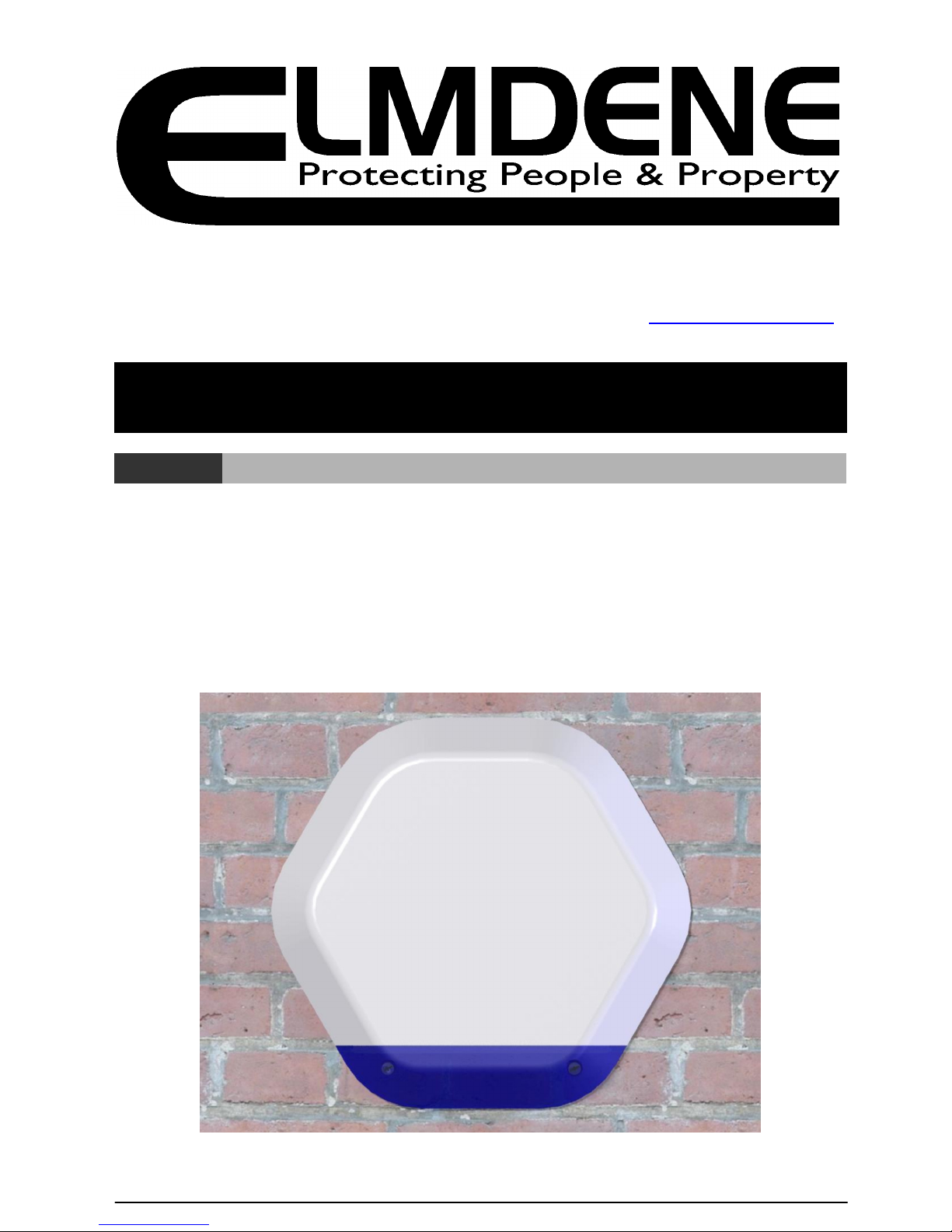
QUARTZ Range
External Sounder
Models
QUARTZ-1000-G2, QUARTZ-3000-G2
F
EATURES
-
High Efficiency Operation
-17mA standby,
-130mA sounding
- Silent Engineer Start-up
- Selectable sound auto cut=off timer
- Selectable SAB or SCB operating mode
-
Integr
al 1 Watt
Xenon tube strobe
- Active inrush current limit on strobe
- Strobe Power Save Mode
- Flashing Comfort LEDs
- Microprocessor controller
- Enclosed electronics module
Elmdene International Ltd
Tel: +44(0)23 9269 6638
3 Keel Close, Interchange Park, Fax: +44(0)23 9266 0483
Portsmouth, Hampshire, PO3 5QD, UK
Web: www.elmdene.co.uk
Technical Support Line +44 (0)23 9269 6638 (Option 3) PAK200360 Iss 03B Mar 2012 ©2012 ELMDENE INTERNATIONAL LTD
O
PERATION
The Quartz sounder is used for notification of an alarm condition as generated within an intruder, holdup or other alarm system. In response to commands from the alarm system control panel, the Quartz will
emit a high intensity sound and/or operate a visual flash.
The Quartz will detect any attempt to gain unauthorised access to the sounder by removal of the cover,
or any attempt to remove it away from its mounting surface. This will generate a tamper signal which is
normally fed back to the alarm control panel.
The Quartz is classified a self powered sounder and has an on-board battery which is recharged via the
external power source. This battery is used to operate the sounder if the external power is removed. The
Quartz can be configured to self actuate (SAB Mode ON) in the event that a tamper condition is detected
or the external power to the sounder is removed.
To assist with commissioning, the Quartz has an Engineer Mode to provide silent start-up. Two Comfort
LEDs are used to provide a heart-beat type visual indication when the Quartz is not sounding.
F
UNCTIONAL INFORMATION
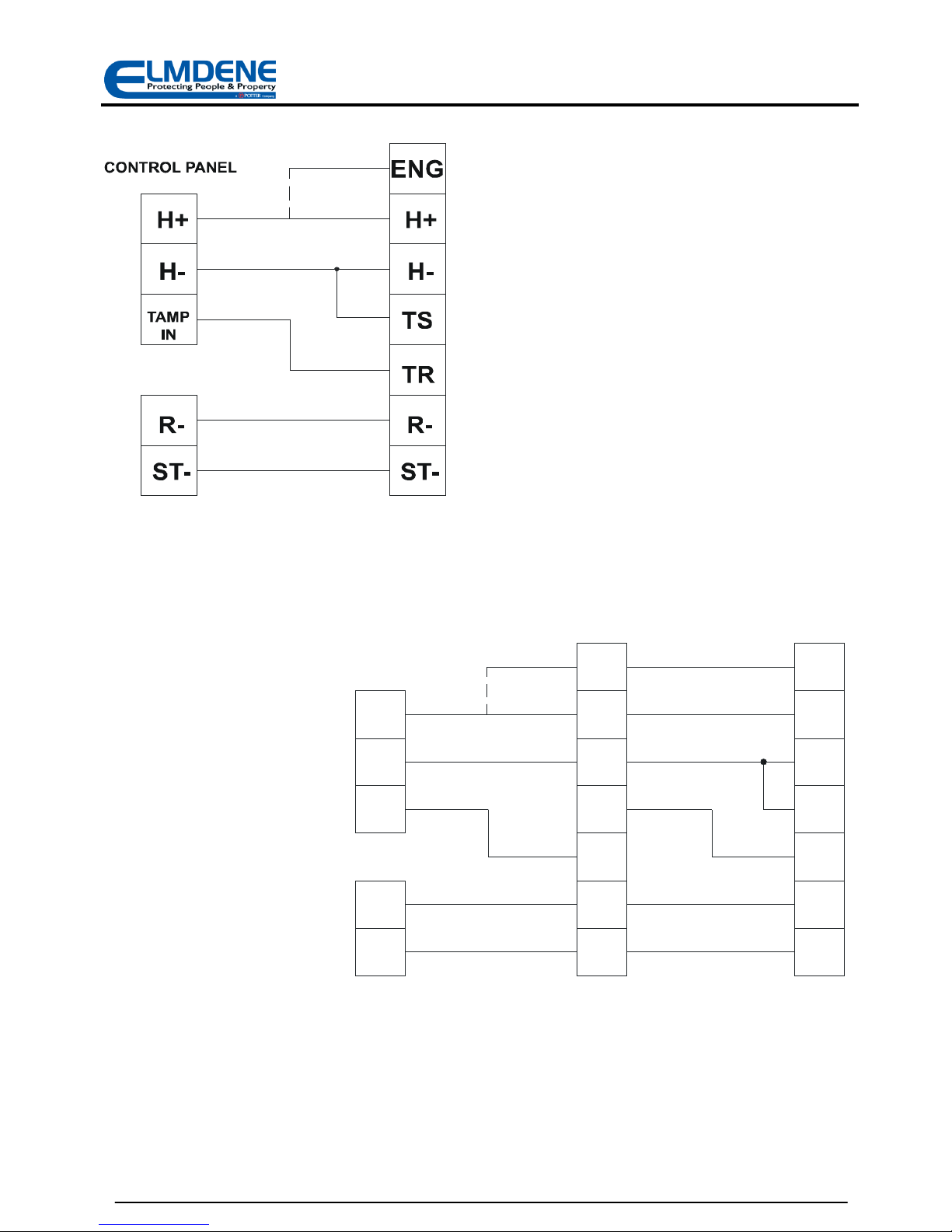
Tamper Circuit for Single or Multiple Cascade Installations
For single sounder installations link TS to H- and connect TR to the control panel Tamper Return input.
(See Fig. 2).
In cascade installations with two or more sounders, the TS (Tamper Source) will normally be connected
to the TR (Tamper Return) of the next sounder except for the last unit which will have TS linked to H-.
(See Fig. 3)
Engineer Mode
This selects silent start-up and silent maintenance. The ENG input may be brought back to the control
panel and connected to a programmable output. Switching this control panel output high when
maintenance is required will prevent the sounder from self activating when the cover is removed or Ractivated. The Tamper output is open when ENG is high, this prevents inadvertent system setting with
the sounder left in Engineer Mode (when SAB Mode = on).
O
PTIONS SELECTION
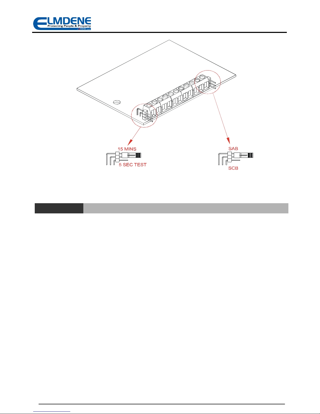
Sound Cut-off Timer
The Quartz sounder will automatically stop sounding after the time period selected by the Sound Cut-off
Timer link, Figure 11, irrespective of the status of the sound trigger (R-) input. The 5s option is provided
to reduce nuisance noise during testing.
SCB/SAB Mode
In SAB mode the sounder can draw current from both the control panel and the battery. The siren will
self-activate if either of the tampers are activated.
In SCB mode the sounder draws the majority of its current from the battery to minimise drain on the
control panel. This allows the user to connect multiple units to a control panel without overloading it.
Select SCB mode using the link next to the terminal blocks (Figure 1.0). In this mode the sounder will NOT
self activate under a tamper condition but the tamper condition will still be signalled back to the control
panel. The control panel can then trigger the siren using the R– line.
Note: The siren will self-activate if the supply lines are cut in either mode.
2
Technical Support Line +44 (0)23 9269 6638 (Option 3) PAK200360 Iss 03B Mar 2012 ©2012 ELMDENE INTERNATIONAL LTD
Figure 1: Jumper Link options
C
ONNECTIONS
BT+ Positive connection to battery.
BT- Negative battery connection. Connect black battery lead after power is applied.
ENG Optional engineer input for quiet operation during installation or
maintenance. In engineer test mode apply a positive signal to
prevent self activation of siren by tamper condition (e.g. lid open).
H+ Permanent positive hold-off supply.
H- Permanent negative hold-off supply.
TS Tamper source: Connect to H– for single unit or last in line. Connect to TR of next unit for
multiple unit installation (see Figure 3.0)
Note each siren has a tamper resistance of 100Ω.
TR Tamper return connection to control panel. (see Figures 2.0 and 3.0)
R- Negative siren trigger.
ST- Negative strobe trigger and supply.
3
Technical Support Line +44 (0)23 9269 6638 (Option 3) PAK200360 Iss 03B Mar 2012 ©2012 ELMDENE INTERNATIONAL LTD
Fig 2: Single Quartz Tamper Connection
ENG
H+
H-
TS
TR
R-
ST-
TAMP
IN
ST-
R-
H-
H+
TS
ST-
TR
R-
H-
H+
ENG
CONTROL PANEL
UNIT 1
UNIT 2
Fig 3: Multiple Cascade Quartz Tamper Connection
4

Technical Support Line +44 (0)23 9269 6638 (Option 3) PAK200360 Iss 03B Mar 2012 ©2012 ELMDENE INTERNATIONAL LTD
I
NSTALLATION AND SET-UP
1. Select a suitable mounting position for the Quartz sounder.
2. Drill holes as required for fixing the backplate to the wall and for cable entry to the rear of the unit.
3. Fit tamper extender (if required), and trim to desired length:
4. Route cable from control panel through cable entry cowl.
5. Fit backplate to wall using minimum of 3 x No. 10 fixing screws suitable for material of mounting
surface.
TAMPER
EXTENDE R
PARKING
COVER SCREW
PARKING
LOOP C ABLE
UNDER C ABLE
CLAMP
5
Technical Support Line +44 (0)23 9269 6638 (Option 3) PAK200360 Iss 03B Mar 2012 ©2012 ELMDENE INTERNATIONAL LTD
C
OMMISSIONING
1) Fit timer link to select 5s sound -off time.
2) Fit link to select SCB or SAB mode as required.
3) Connect ENG input to H+ or to a switched output of control panel set high.
4) Apply power to the sounder via H+ and H- from control panel.
5) Connect R-, ST- and TR to their respective outputs on the control panel.
6) Connect the black battery lead to BT- (slide sleeve to expose conductor).
7) Check tamper signal is present at control panel (circuit open). This verifies the ENG function.
8) Disconnect ENG input (or switch low from panel). Note: Sounder will operate
9) Fit cover. Sounder will stop. This verifies the tamper operation.
10) Check tamper signal is removed at control panel (circuit closed).
11) Test sounder by triggering R- input.
12) Test strobe operation by triggering ST- input.
13) Remove cover. Note: Sounder will operate and a tamper will be signalled to the control panel.
14) Remove timer link to select 15min sound -off time.
15) Re-fit cover and secure using fixing screws.
16) Disconnect H+ and check that the siren activates. Restore H+.
17) Disconnect H- and check that the siren activates. Restore H-.
18) Commissioning complete.
M
AINTENANCE
The Quartz sounder should be tested for correct operation on a periodic basis. A minimum of one
check every 12 months is recommended. The following features should be verified on each
maintenance visit:
1) Correct operation of sounder and strobe from control panel signals
2) Correct operation of cover and rear tampers.
3) Remove the H+ supply from the control panel and check that the internal battery voltage as
measured between BT+ and BT- is greater than 6.0v dc. If the battery voltage is less than this
value replace the battery and re-connect observing CORRECT polarity.
4) Check for signs of significant water or insect ingress. Clean as necessary.
SAB B
ATTERY REMOVAL
The SAB battery may be removed for disposal at end of product life or if it is detected faulty when
tested (see Maintenance above). To remove the battery, disconnect red and black leads from BT+
and BT- and unclip battery from holder. To fit a new battery, clip into holder, route battery cables
around clips and reconnect positive (RED) lead to BT+ and negative (BLACK) lead to BT-.
IMPORTANT: Ensure correct polarity of connections and that exposed battery leads DO NOT
accidentally touch.
Dispose of used batteries in accordance
with all national and local regulations
6
Technical Support Line +44 (0)23 9269 6638 (Option 3) PAK200360 Iss 03B Mar 2012 ©2012 ELMDENE INTERNATIONAL LTD
F
AULT FINDING
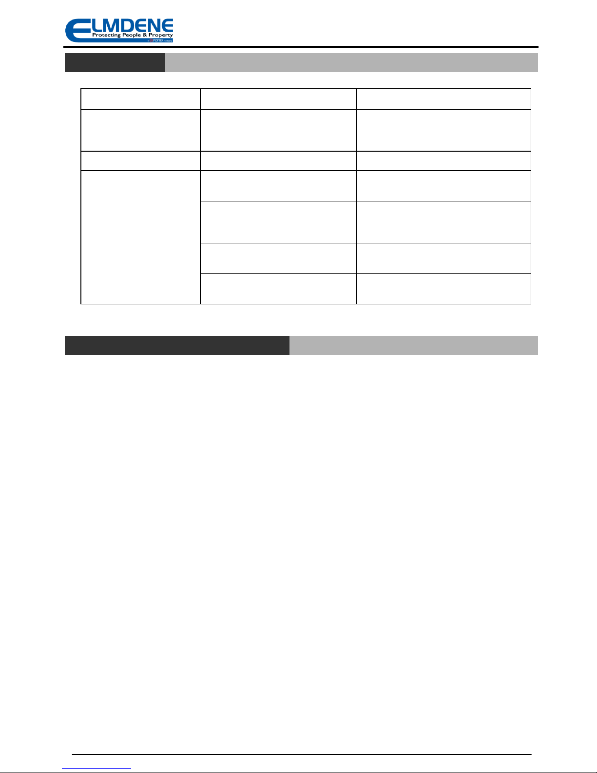
Symptom Fault Action
Sounder activated in nonalarm condition and tamper
shows at panel
Cover not closed correctly. Check cover closed and screws secure.
Rear tamper pin not correct length Correct rear tamper pin length.
Sounder stops after 5s Incorrect timer link setting Set correct timer jumper links.
Cannot SET control panel
(due to sounder tamper)
Tamper output open due to ENG input
still connected to H+
Disconnect ENG from H+ in sounder or set
control panel programmable output low.
Tamper Source (TS) not connected to
H- for single sounder or to Tamper
Return (TR) for cascaded sounders
Refer to connection diagrams for single
and cascaded sounders (Figures 2 and 3).
Total resistance of tamper circuit too
high for multiple sounder installations
Reduce number of cascaded sounders on
one tamper loop.
Cover or Rear tamper switch not
closed.
Check cover and rear tamper switches fully
closed.
D
ISPOSAL OF PRODUCT AT END OF LIFE
This product falls within the scope of EU Directives 2002/96/EC Waste Electrical and Electronic Equipment
(WEEE) and 2006/66/CE (Battery). At the end of life, the product must be separated from the domestic
waste stream and disposed via an appropriate approved WEEE disposal route in accordance with all
national and local regulations.
Before disposal of the product, the SAB battery must be removed and disposed separately via an
appropriate approved battery disposal route in accordance with all national and local regulations. Package
used batteries safely for onward transport to your supplier, collection point or disposal facility.
Caution risk of fire or explosion
if bare battery wires are allowed to touch.
See Specification for battery type information. The battery is marked with the crossed out wheelie bin
symbol, which may include lettering to indicate cadmium (Cd), lead (Pb), or mercury (Hg).
For more information see: www.recyclethis.info
7

Technical Support Line +44 (0)23 9269 6638 (Option 3) PAK200360 Iss 03B Mar 2012 ©2012 ELMDENE INTERNATIONAL LTD
S
PECIFICATION
Sounder Volume 105 dB(A) single piezo (QUARTZ-1000-G2)
108 dB(A) dual piezo (QUARTZ-3000-G2)
Cut off Timer 15 minutes max (5 second test)
Waterproofing All electronics conformal coated
Operating Temp -25 to + 60 °C
Storage Temp -25 to + 70 °C
Supply Voltage
9—15V d.c. (13.8 V d.c. nominal)
Current
15 mA max. Quiescent
130 mA max. Sounder
120 mA max. Strobe
Battery
Type Ni-MH
Voltage 6.0V
Capacity 320 mAH
Strobe
Rating 1 Watt
Flash Rate 1 Hz reduces to 1/2 Hz after 15 minutes
Comfort LEDs
Alternate flash, 60 per minute
Material 3mm Polycarbonate—all parts
Tamper Detection Cover and Rear
Kinetic Protection IK08
C
OMPLIANCE
This product meets the essential requirements of the following EU Directives:
EMC: 2004/108/EC
RoHS: 2002/95/EC
WEEE: 2002/96/EC
Battery: 2006/66/EC
EN50131-4:2009 Security Grade 2
Environmental Class IV
This product is suitable for use in systems designed to comply with PD6662:2010 at:
Grade 2 and Environmental Class IV.
The packaging supplied with this product may be recycled.
Please dispose of packaging accordingly.
8
 Loading...