


Models
108
dB(A) siren output
Full SAB using internal battery
Elmdene International Ltd
3 Keel Close, Interchange Park, Fax: +44(0)23 9266 0483
Portsmouth, Hampshire, PO3 5QD, UK
Tel: +44(0)23 9269 6638
Web: www.elmdene.co.uk
QUARTZ-G3 Range
External Sounder
F
EATURES
-
- 12v dc voltage operation
- Integral low current LED strobe.
- 2 way tamper protection: cover & rear
- Separate sound and strobe trigger inputs
- Hold-off supply failure detection
- Battery and piezo test with fault output
- Selectable sound auto cut-off timer: 5s (for test)
or 15 minutes
QUARTZ-1000-G3, QUARTZ-3000-G3
-
- Twin Comfort LEDs selectable on, off, alternate
flash
- Audible Tamper to assist commissioning
- Ring Line Monitoring
- Engineer Mode for quiet installation and
maintenance
- Polycarbonate cover and backplate
- Microprocessor controlled
Technical Support Line +44 (0)23 9269 6638 (Option 3) PAK200544 Iss 01A Mar 2012 ©2012 ELMDENE INTERNATIONAL LTD
O
PERATION
The Quartz-G3 sounder is a high specification external warning device for use in intruder, hold-up or other
alarm systems, fully meeting the requirements for EN50131-4 at Security Grade 3 and Environmental Class
IV.
The Quartz-G3 sounder is used for notification of an alarm condition as generated within an intruder, holdup or other alarm system. In response to commands from the alarm system control panel, the Quartz-G3
will emit a high intensity sound and/or operate a visual flash.
The Quartz-G3 will detect any attempt to gain unauthorised access to the sounder by removal of the
cover, or any attempt to remove it away from its mounting surface. This will generate a tamper signal
which is normally fed back to the alarm control panel. Integrity of the Trigger command (Ring Line)
connection is constantly monitored and will cause the unit to self-activate and report a tamper to the
control panel if loss of connection is detected.
The Quartz-G3 is classified a self powered sounder and has an on-board battery which is recharged via the
external power source. This battery is used to operate the sounder if the external power is removed. The
Quartz-G3 will self actuate in the event that a tamper condition is detected or the external power to the
sounder is removed.
Every 24 hours the Quartz-G3 performs a self test to check the integrity of its on-board battery, its battery
charging circuit and its piezo transducers. If an error condition is detected, a fault signal is generated. This
is normally connected back to the control panel. An on-board diagnostic LED guides the maintenance
engineer to the source(s) of the fault.
To assist with commissioning, the Quartz-G3 has an Engineer Mode to provide silent start-up and Tamper
Tones that indicate the correct closure of the tamper detection switches.
Two Comfort LEDs are used to provide a heart-beat type visual indication when the Quartz-G3 is not
sounding.
F
UNCTIONAL INFORMATION
Tamper Circuit for Single or Multiple Cascade Installations
For single sounder installations link TS to H- and connect TR to the control panel Tamper Return input.
(See Fig. 2).
In cascade installations with two or more sounders, the TS (Tamper Source) will normally be connected to
the TR (Tamper Return) of the next sounder except for the last unit which will have TS linked to H-. (See
Fig. 3)
A Tamper signal will be generated when ANY of the following conditions exist:
- Cover removed
- Removed from mounting surface
- Connection to R- is lost
- H+ or H- power connections lost
- ENG input taken high (e.g.: to H+)
Engineer Mode
This selects silent start-up and silent maintenance. The ENG input may be brought back to the control
panel and connected to a programmable output. Switching this control panel output high when
maintenance is required will prevent the sounder from self activating when the cover is removed or R-
2
Technical Support Line +44 (0)23 9269 6638 (Option 3) PAK200544 Iss 01A Mar 2012 ©2012 ELMDENE INTERNATIONAL LTD
activated. The Tamper output is open when ENG is high, this prevents inadvertent system setting with the
sounder left in Engineer Mode.
3
Self Test and Fault Output
The Quartz-G3 performs a self test every 24 hours. This function tests the condition of the battery and
piezo sounders. If a fault is found the Fault output will open. The fault source can be identified using the
Diagnostic LED - see “Diagnostics”. This is ONLY enabled when the cover is opened (top tamper active) for
longer than 5s.
The Fault output will be cleared (output closed) when:
- the fault has been cleared, e.g. battery (re)connection
- the fault has been cleared and the sounder performs its next 24hour self test
- the fault has been cleared and the sounder has been disconnected from H+ AND the SAB battery has
been disconnected (hardware reset)
O
PTIONS SELECTION
Sound Cut-off Timer
The Quartz-G3 sounder will automatically stop sounding after 15 minutes unless J9 is removed, in which
case the sound will cut off after 5 seconds.
Comfort LEDs
A wire loop is provided at J5 position, cutting this loop will disable the comfort LEDs.
C
ONNECTIONS
Piezo (2) Connections to sounder module(s)
BT+ Positive connection to battery.
BT- Negative battery connection. Connect black battery lead after power is applied.
Fault (2) Fault output: voltfree contacts, max 16ohm resistance, max 100mA rating
ENG Optional engineer input for quiet operation during installation or
H+ Permanent positive hold-off supply.
H- Permanent negative hold-off supply.
TS Tamper source: Connect to H– for single unit or last in line. Connect to TR of next unit for
TR Tamper return connection to control panel. (See Figures 2.0 and 3.0)
R- Negative siren trigger.
ST- Negative strobe trigger and supply.
maintenance. In engineer test mode apply a positive signal to
prevent self activation of siren by tamper condition (e.g. lid open).
multiple unit installation (see Figure 3.0)
Technical Support Line +44 (0)23 9269 6638 (Option 3) PAK200544 Iss 01A Mar 2012 ©2012 ELMDENE INTERNATIONAL LTD
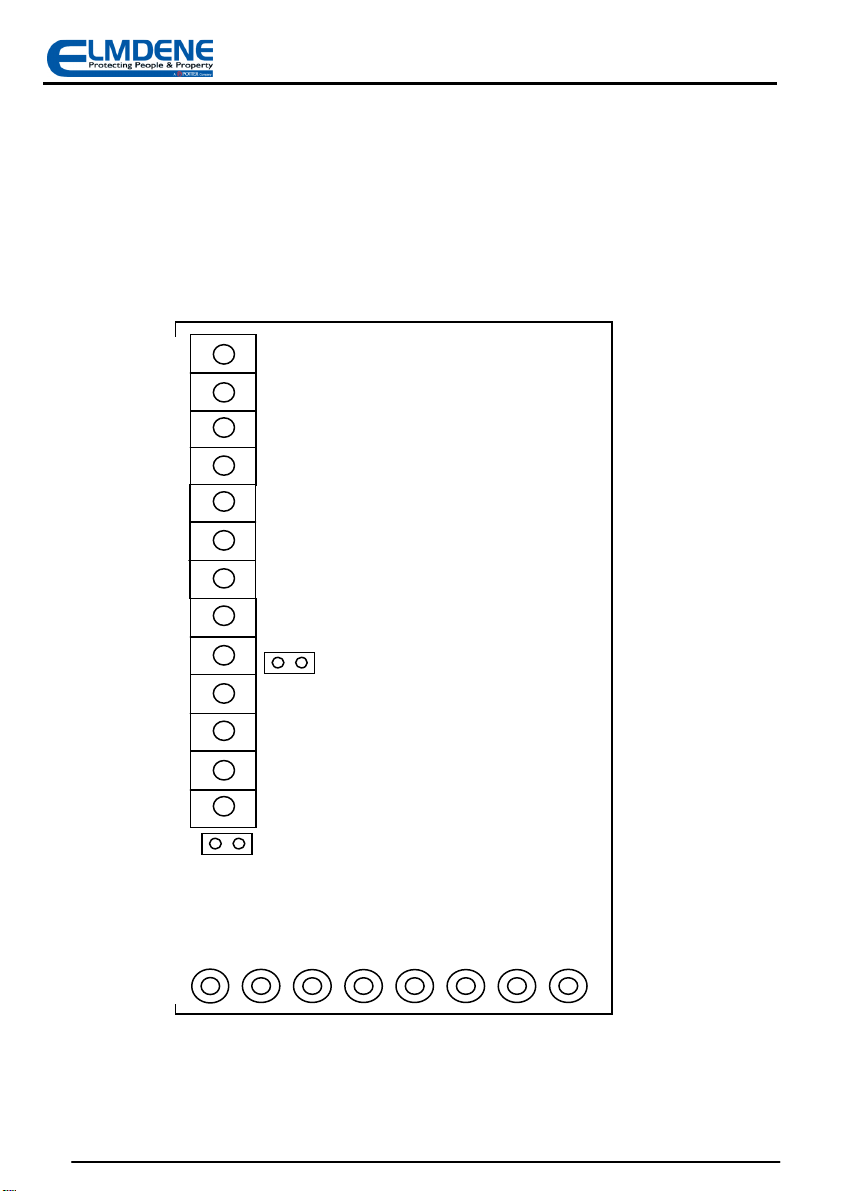
J9
J5
BATT +
BATT –
Piezo
Piezo
Fault
Fault
ENG
H +
4
H –
TS
TR
R –
ST –
Figure 1: Board Connections
Technical Support Line +44 (0)23 9269 6638 (Option 3) PAK200544 Iss 01A Mar 2012 ©2012 ELMDENE INTERNATIONAL LTD

ENG
ST-
TS
ST-
ENG
CONTROL PANEL
UNIT 1
UNIT 2
See Note 1.
See Note 1.
Temporary
Link (See
CONT ROL PA NEL
ENG
5
H+
H+
H-
H-
TAM P
IN
TS
TR
R-
R-
ST-
ST-
Fig 2: Single Quartz-G3 Tamper Connection
Temporary
Link (See
Note 2)
Technical Support Line +44 (0)23 9269 6638 (Option 3) PAK200544 Iss 01A Mar 2012 ©2012 ELMDENE INTERNATIONAL LTD
H+
H-
TAMP
IN
R-
H+
H-
TS
TR
R-
H+
H-
TR
R-
ST-
Note 1.
Where the siren trigger is NOT pulled up to > +8.5V by the control panel when in standby mode, or
is operated via volt-free contacts, it will be necessary to fit a pull-up resistor (any value between 1k0
and 10k), as shown, at the control panel to enable monitoring of the Trigger connection.
Note 2.
If preferred, pull the ENG i/p high using a programmable control panel output, rather than wiring it
directly to H+.
Fig 3: Multiple Cascade Quartz-G3 Tamper Connection

TAMPER
EXTENDER
COVER SCREW
UNDER CA BLE
I
NSTALLATION AND SET-UP
1. Select a suitable mounting position for the Quartz-G3 sounder.
2. Drill holes as required for fixing the backplate to the wall and for cable entry to the rear of the unit.
3. Fit tamper extender (if required), and trim to desired length:
6
4. Route cable from control panel through cable entry cowl.
5. Fit backplate to wall using minimum of 3 x No. 10 fixing screws suitable for material of mounting
surface.
PARKING
LOOP CABLE
CLAMP
PARKING
Fig 4: Backplate Mounting Positions
Technical Support Line +44 (0)23 9269 6638 (Option 3) PAK200544 Iss 01A Mar 2012 ©2012 ELMDENE INTERNATIONAL LTD

C
OMMISSIONING
1) Cut Comfort LED loop if Comfort LEDs are NOT required.
2) Connect ENG i/p to a switched output of the control panel (set high), or to H+.
3) Apply power to the sounder via H+ and H- from control panel.
4) Connect the black battery lead to BT- (slide sleeve to expose conductor).
5) Check that tamper signal is present at the control panel.
6) Manually operate the rear tamper. As the rear tamper closes the piezo will emit a low level click.
As it opens the piezo will emit a double click. If the rear tamper extender is required, trim to
length as necessary with pliers or side cutters.
7) Fix backplate securely to the wall using a minimum of 3 x No. 10 fixing screws suitable for the
material of the mounting surface. (See Fig. 4)
8) Fit cover. As the front tamper closes the piezo will emit a low level click. As it opens the piezo will
emit a double click.
9) When the cover is closed the unit will perform a self-test. This takes approximately 5 seconds. If
the battery is faulty the unit will indicate this with a series of fast clicks from the piezo. If the rear
tamper is not closed the unit will indicate this with a series of slow clicks.
10) Remove cover. If connected, disconnect ENG from H+. If ENG is connected to control panel, set
output LOW. NOTE: Sounder will activate.
11) Refit the cover.
12) Test sounder by triggering R- input.
13) Test strobe operation by triggering ST- input.
14) If necessary, open the cover to fit timer link to select 15min sound -off time.
15) Re-fit cover and secure using fixing screws.
16) Disconnect H+ and check that the siren activates. Restore H+.
17) Disconnect H- and check that the siren activates. Restore H-.
18) At control panel, disconnect R-, check siren activates and reports a tamper to the control panel,
then reconnect R-
19) Commissioning complete.
M
AINTENANCE
The Quartz-G3 sounder should be tested for correct operation on a periodic basis. A minimum of one
check every 12 months is recommended. The following features should be verified on each maintenance
visit:
1) Correct operation of sounder and strobe from control panel signals
2) Correct operation of cover and rear tampers.
3) Remove the H+ supply from the control panel and check that the internal battery voltage as
measured between BT+ and BT- is greater than 6.0v dc. If the battery voltage is less than this
value replace the battery and re-connect observing CORRECT polarity.
4) Check for signs of significant water or insect ingress. Clean as necessary.
7
SAB B
ATTERY REMOVAL
The SAB battery may be removed for disposal at end of product life or if it is detected faulty when tested
(see Maintenance above). To remove the battery, disconnect red and black leads from BT+ and BT- and
unclip battery from holder. To fit a new battery, clip into holder, route battery cables around clips and
reconnect positive (RED) lead to BT+ and negative (BLACK) lead to BT-.
IMPORTANT: Ensure correct polarity of connections and that exposed battery leads DO NOT accidentally
touch.
Dispose of used batteries in accordance with all national and local regulations
Technical Support Line +44 (0)23 9269 6638 (Option 3) PAK200544 Iss 01A Mar 2012 ©2012 ELMDENE INTERNATIONAL LTD

Use to ensure t
hat the rear tamper has been
8
D
IAGNOSTICS
A green LED is provided for fault diagnosis. The Fault Diagnostic LED becomes active when the front cover
is opened. Temporarily select a 5 second sounder timeout or set Engineer mode to active to ensure fault
indication tracks changes in fault status.
Note: Commissioning Mode is only active when ENG is connected to 9V to 15Vdc.
Commissioning
Tones
Status Indicated Action
Single Click Tamper closing – front or rear
Double Click Tamper opening – front or rear
Continuous slow
clicks
Continuous fast
clicks
Rear tamper not closed when
cover tamper is closed
Battery not connected or faulty
when cover tamper is closed
trimmed or extended to the correct length,
or that the cover has been fully closed.
Use to verify correct operation of tamper
circuit
Remove unit from wall and adjust rear
tamper until it closes when the unit is
correctly fitted.
Open cover and check that battery is
correctly connected.
NOTE: Diagnostic LED only activated when Cover is open
Diagnostic LED Status Indicated Action
Single Flash Battery voltage low
2 Flashes
3 Flashes
4 Flashes
Battery test failed Change battery
Piezo self test failed Change sounder
Battery charger failure Change sounder
Change battery (unless newly fitted and is
still charging)
Technical Support Line +44 (0)23 9269 6638 (Option 3) PAK200544 Iss 01A Mar 2012 ©2012 ELMDENE INTERNATIONAL LTD

9
F
AULT FINDING
Symptom Fault Action
Cover not closed correctly. Check cover closed and screw secure.
Sounder activated in nonalarm condition and tamper
shows at panel
Sounder stops after 5s Incorrect timer link setting Set correct timer jumper links.
Cannot SET control panel
(due to sounder tamper)
Fault output open
Clicking noise from sounder
during commissioning
Rear tamper pin not correct length Correct rear tamper pin length.
R- not pulled up to +12V in standby
mode
Tamper output open due to ENG input
still connected to H+
Tamper Source (TS) not connected to Hfor single sounder or to Tamper Return
(TR) for cascaded sounders
Total resistance of tamper circuit too
high for multiple sounder installations
Cover or Rear tamper switch not closed.
Ring trigger signal (R-) disconnected
(floating)
Battery not connected
Battery faulty or voltage low Replace battery.
Piezo fault
Battery charger faulty
See Commissioning Mode table.
Fit pull up resistor to R- at control panel.
See Fig 1, Note 1
Disconnect ENG from H+ in sounder or set
control panel programmable output low.
Refer to connection diagrams for single
and cascaded sounders (Figures 1 and 2).
Reduce number of cascaded sounders on
one tamper loop.
Check cover and rear tamper switches fully
closed.
Ensure R- pulled up to above 8.5V.
Check battery connections to terminal
block.
Return unit to manufacturer.
D
ISPOSAL OF PRODUCT AT END OF LIFE
This product falls within the scope of EU Directives 2002/96/EC Waste Electrical and Electronic Equipment
(WEEE) and 2006/66/CE (Battery). At the end of life, the product must be separated from the domestic
waste stream and disposed via an appropriate approved WEEE disposal route in accordance with all
national and local regulations.
Before disposal of the product, the SAB battery must be removed and disposed separately via an
appropriate approved battery disposal route in accordance with all national and local regulations. Package
used batteries safely for onward transport to your supplier, collection point or disposal facility.
Caution: risk of fire or explosion
if bare battery wires are allowed to touch.
See Specification for battery type information. The battery is marked with the crossed out wheelie bin
symbol, which may include lettering to indicate cadmium (Cd), lead (Pb), or mercury (Hg).
Technical Support Line +44 (0)23 9269 6638 (Option 3) PAK200544 Iss 01A Mar 2012 ©2012 ELMDENE INTERNATIONAL LTD
For more information see: www.recyclethis.info

Supply Voltage
Current
Battery
Strobe
Comfort LEDs
S
PECIFICATION
Sounder Volume 105dB(A) single piezo (QUARTZ-1000-G3)
108 dB(A) dual piezo (QUARTZ-3000-G3)
Cut off Timer 15 minutes max (5 second test)
Waterproofing All electronics conformal coated
Operating Temp -25 to + 60 °C
Storage Temp -25 to + 70 °C
160 mA max. Sounder (QTZ-1000-G3)
40 mA max. Strobe
Type Ni-MH
Voltage 6.0V
Capacity 320 mAH
Flash Rate 1 Hz reduces to 1/2 Hz after 15 minutes
Material 3mm Polycarbonate—all parts
Tamper Detection Cover and Rear
Kinetic Protection IK08
C
OMPLIANCE
This product meets the essential requirements of the following EU Directives:
EN50131-4:2009 Security Grade 3
Environmental Class IV
This product is suitable for use in systems designed to comply with PD6662:2010 at:
Grade 3 and Environmental Class IV.
9—15V d.c. (13.8 V d.c. nominal)
16 mA max. Quiescent
190 mA max. Sounder (QTZ-3000-G3)
Alternate flash, 85 per minute
EMC: 2004/108/EC
RoHS: 2002/95/EC
WEEE: 2002/96/EC
Battery: 2006/66/EC
The packaging supplied with this product may be recycled.
Please dispose of packaging accordingly.
10
Technical Support Line +44 (0)23 9269 6638 (Option 3) PAK200544 Iss 01A Mar 2012 ©2012 ELMDENE INTERNATIONAL LTD
 Loading...