


1
Technical Support: +44(0)23 9269 6638 (option 3) PAK200574_01K May 2016 ©2016 ELMDENE INTERNATIONAL LTD
27.6 Vdc Switch Mode Power Supply for Fire – EN54-4:1997 +A1 +A2
STX2410-E Optional BATT-BOX-65
STX2410-H
F
EATURES
The STX2410-x is an EN54-4:1997 +A1 +A2 approved power supply ideal for use in Fire control
Systems. Its regulated 27.6V dc output will supply a total of 10 Amps continuous into the load, whilst
also enabling battery charging. (7.2 Amps Load with 65Ah batteries, 10 Amps with 18Ah batteries).The
power supply output features electronic short circuit protection under both mains and standby
battery operation. Maximum battery life is assured through continuous active battery monitoring and
the use of a three stage charger, comprising bulk, absorb and temperature compensated final float
phase depending upon battery condition. Once fully charged the product operates in Eco power
saving mode, whereby the batteries are charged for 4 hours in every 24 hour period while still being
continuously monitored. This reduces wasted energy in charging already fully charged batteries and
extends their working life. Deep discharge protection prevents premature battery failure when
operating from standby for extended periods. Two sets of volt free solid state relay fault output signal
(i) loss of mains and (ii) battery fault, charger fault and loss of output. In addition there is an RS232
serial interface that can provide diagnostic and fault reporting information to supervisory systems.
• Certified by UL to EN54-4:1997 +A1 +A2.
• Up to 10 A current to load at 27.6V dc nominal regulated output.
• Charging capability to support 18, 38 or 65Ah batteries with intelligent load enhancement.
• Electronic overload protection shuts down output until overload or short circuit is removed.
• Battery Monitor detects battery missing, low battery, short-circuit or reverse connection or
circuit impedance (Ri) in excess of 300mΩ caused by connector or wiring corrosion within
4hours..
• Battery charging circuit is energised only when a battery is correctly connected and the battery
voltage is greater than 14 V.
• No loss of output during automatic connection of battery to load on loss of mains.
• Deep discharge protection disconnects battery from load when battery voltage falls to 21 V.
• Fault indicator LED (Yellow) flashes on detection of output fault, battery fault, charger fault and
mains failure.
• Mains indicator LED (Green) showing mains present.
• RS232 serial interface for fault reporting and diagnostics interface to OEM equipment.
Elmdene International Ltd
Tel: +44(0)23 9269 6638
3 Keel Close, Interchange Park, Fax: +44(0)23 9266 0483
Portsmouth, Hampshire, PO3 5QD, UK
Web: www.elmdene.co.uk
0843-CPR-0216
14
2
Technical Support: +44(0)23 9269 6638 (option 3) PAK200574_01K May 2016 ©2016 ELMDENE INTERNATIONAL LTD
S
PECIFICATION
Mains Input
Rated Voltage
110 – 240V
ac
Frequency
50 Hz
I
nput current
<
4.0 Amps at full load
Inrush current
30
A Max at 25 °C 110V
ac for 10
ms
Fuse
T4.0 A, 20 mm, 250V
ac HRC
Output
Voltage at full load
Mains power
Battery standby
26.0 – 28.5 Vdc (range) (27.6 V nominal)
18 – 26.0 Vdc
Ripple
<100 mV pk
– pk max
@ Rated Voltage
Fuse
Load
Battery
F10.0 A
F10.0 A
Overload
Electronic shutdown at 15
A until overload or short circuit removed
Battery mode selected
17/
18 Ah
38 Ah
65 Ah
Continuous Output Current
No charging (Imax B)
With charging (Imax A) – 220V
With charging (Imax A) – 110V
10.0 A
10.0 A
8.5 A
10.0 A
8.0 A
7.5 A
10.0 A
7.2 A
6.5 A
Battery Capacity
eg
- PowerSonic model
- Yuasa model
- Interlogix model
2 x 17
/18
Ah 12 V
PS12170
NP17-12
BS131N
2 x 38 Ah 12 V
PS12380
NP38-12
2 x 65 Ah 12 V
PS12650
NP65-12
BS133N
Battery Charging
Constant current bulk charging to 80% capacity within 24 hours
Float charging to 100% within 48 hours
Eco charging and check every 2 hours – (for 20 minutes)
Constant current charge
0.7 A
1.6 A
2.6 A
Low battery thresho
ld voltage
23 V
Deep discharge protection
Threshold voltage
– 21 V
Quiescent current
– no load
30 mA
Quiescent current
– batt cut off
0 mA
Mechanical
Product
Reference
STX2410
-E
STX2410
-H
BATT
-
BOX-65
Enclosure Dimensions
w x h x d (mm)
400 x 420 x 80 420 x 420 x 180 450 x 535 x 245
Weight (kg)
excluding battery
6.4 9.7 12.9
Material
1.2mm steel white powder coated
Environmental
Temperature
– Operating
-10 to +40°C (operating) 75% RH non
-
condensing
Temperature
- Storage
-20 to +80°C (storage)
3
Technical Support: +44(0)23 9269 6638 (option 3) PAK200574_01K May 2016 ©2016 ELMDENE INTERNATIONAL LTD
C
ONNECTIONS
Load Output ++ /
-- Screw terminals
Voltage output to load
GEN
PSU Fault
(normally
closed contact)
0.10 A @ 60
V
dc 16
Ω solid state relay contact
s, volt free
Open if Mains failed and battery voltage < 23V or fault PSU fault
condition, (see below)
EPS Fault (normally closed
contact)
0.10 A @ 60
V
dc 16
Ω solid state relay contacts, volt free
Open if loss of mains for > 10 seconds
Temperature sensor
Therm
istor input from supplied battery terminal
therm
istor.
BATT + /
- Connection to b
ack up battery using supplied battery lead
FAN +/
- Not used
RS232 serial interface
4
pin header
S
IGNALLING AND DIAGNOSTICS
Fault Outputs
EPS Fault GEN Fault Condition Possible Cause Action
C
LOSED
C
LOSED
Normal
operation
Mains present
Battery healthy
None
O
PEN
C
LOSED
Standby
Mode
Mains lost
Battery driving load
Investigate loss of mains
C
LOSED
O
PEN
Fault
Present
Blown fuses
Battery fault
Overload
Internal fault
Investigate fault source
using diagnostic LED
Rectify fault where
possible
O
PEN
O
PEN
PSU
Shutdown
Mains lost
Standby battery exhausted
Restore mains as soon
as possible
LED Indication
YELLOW
LED
Fault LED
GREEN LED
Mains supply On
DIAGNOSTICS
Diagnostic LED (Not visible through front panel)
Fault Diagnostic table – Front panel - User
Yellow LED
Fault
Green LED
Mains
Condition Possible Cause Action
OFF ON
Normal
operation
Mains present
Battery healthy
None
F
LASH
C
ONTINUOUS
ON or OFF Fault
Blown fuses
Battery fault
Overload
Internal fault
Contact service
engineer
1 P
ULSE
OFF Standby Mode
Mains lost
Battery driving load
Investigate loss of
mains

4
Technical Support: +44(0)23 9269 6638 (option 3) PAK200574_01K May 2016 ©2016 ELMDENE INTERNATIONAL LTD
Fault Diagnostic table – Internal - Engineer
Orange
LED
Diagnostic
Green LED
Mains
Condition Possible Cause Action
OFF
ON
Normal
operation
Mains present
Battery fully charged
None
OFF
Standby
Operation
Mains Lost. No faults present
Battery driving load
Investigate loss of mains
F
LASH
C
ONTINUOUS
ON or OFF No output
Output fuse blown
Output overload
Output short circuit
Check and replace
output fuse
Disconnect output load
and test load
1 P
ULSE
ON
Battery
Charging
No faults active
Battery charging normally
but
< 90% of full charge
None
2 P
ULSES
ON No Battery
Battery disconnected
Battery fuse blown
Battery heavily discharged
Check battery
connections
Check battery fuse
Check battery condition
Replace battery if aged
OFF
Low Battery
Volts
Standby Mode
Battery almost discharged
Restore mains
3 P
ULSES
ON or OFF Battery Fault
High impedance in battery
connection
Battery internal fault
Check battery
connections for
corrosion. Replace
battery if aged
4 P
ULSES
ON or OFF Charger Fault
Internal failure of battery
charger
Return to manufacturer
5 P
ULSES
ON or OFF
Battery
Temperature
Probe Fault
Battery temperature monitor
disconnected or damaged
PSU running in Safe Mode
Check temperature
sensor connections and
condition of sensor.
Replace if suspect
O
N
C
ONTINUOUS
ON or OFF Internal Fault
Software fault detected
PSU running in Safe Mode
Return to manufacturer
I
NSTALLATION
This unit is only suitable for installation as permanently connected equipment. The PSU is NOT SUITABLE for
external installation. This product (PSE) is designed for the use in automatic fire detection and fire alarm systems. If
it is used as power supply equipment for control and indicating equipment, the PSE shall be installed no further
than 10cm from the CIE, and close coupled by conduit.
This unit must be fed from a mains power source having a separate (approved) disconnect device and fitted with a
fuse or other over-current protection device rated at 5 A maximum. Ensure that the disconnect device used has
appropriate earth fault protection to the applicable standard.
Where the PSU is used to provide power to a fire alarm circuit, the mains isolation and disconnect device should be
provided solely for this purpose and be suitably marked “FIRE ALARM – DO NOT TURN OFF”. All cabling should meet
national and local fire system installation regulations, e.g. FP200 type cable for high integrity installations.
Where the PSU is used for other applications, it should be installed according to all relevant safety regulations
applicable to that application.

5
Technical Support: +44(0)23 9269 6638 (option 3) PAK200574_01K May 2016 ©2016 ELMDENE INTERNATIONAL LTD
Where the PSU Fault and EPS Fault outputs are used, they should only be connected to circuits having voltages less
than 60 Vdc.
Cable Sizing
1) Mains input cable must be to the applicable standard with a 5 A or greater current capacity, i.e. 0.75 mm2
nominal conductor area, having a minimum operating voltage of 300/500 Vac.
2) The low voltage output cable must be sized to carry the rated load current to the devices connected to the
PSU.
3) Mains input and low voltage output cables should be routed to use different entry / exit holes in the case.
Bushes should be used to protect cable sheaths from chafing. Ensure that these bushes are correctly sized
(i.e. close fitting with respect to cable sizing). Note that the bushes should meet a minimum flammability
specification of UL94 HB.
4) All cabling should be securely fastened in position using a cable tie through the saddles provided.
Mounting – E box – 17 or 18 Ah
5) The E box is designed to support two 17 or 18 Ah batteries and as such weighs a total of 19.5 Kg when
loaded. Ensure that wall fixings are appropriate to support this weight.
6) The product should be mounted no further than 10 cm from the control and indicating equipment, close
coupled by conduit if it is being used to power the CIE directly.
7) Fix to wall or other support structure in correct orientation i.e. with hinge on left hand side, using screws
of sufficient size and length through the mounting holes.
8) Protect the battery terminals from any metal surfaces during installation as shorting of the terminals is
extremely hazardous.
9) Knock-outs are provided in the case for mating with external trunking or conduit.
10) Ensure that all unused holes (on the rear of the case) are sealed to prevent the ingress of damp and dust.
Figure 1 – E Box and Battery mounting
Mounting – BATT- BOX – 65 Ah
11) The Battery box is used for 65 Ah batteries is designed to be floor mounted. DO NOT suspend from a wall.
12) It is important that the battery box and the PSU are co-located as shown, and connected using the
provided extended 3 metre cable.
13) A fixing bracket is provided to secure the Battery Box to the wall to prevent it moving away from the wall.

6
Technical Support: +44(0)23 9269 6638 (option 3) PAK200574_01K May 2016 ©2016 ELMDENE INTERNATIONAL LTD
Figure 2 – E Box and Battery box mounting
Mounting – H Box – 38 Ah
14) The H box is designed to handle and support two 38 Ah batteries and as such weighs a total of
approximately 40 Kg when loaded. Ensure that wall fixings are appropriate and designed to support this
weight.
15) The product should be mounted no further than 10 cm from the control and indicating equipment, close
coupled by conduit if it is being used to power the CIE directly.
16) Fix to wall or other structure in correct orientation i.e. with hinge on left hand side, using screws of
sufficient size and length through the mounting holes.
17) Protect the battery terminals from any metal surfaces during installation as shorting of the terminals is
extremely hazardous.
18) Knock-outs are provided in the case for mating with external trunking or conduit.
19) Ensure that all unused holes (on the rear of the case) are sealed to prevent the ingress of damp and dust.
Figure 3 – H Box and Battery box mounting
Floor
Spacing
Spacing shall be greater
than 20 mm and less
than 300 mm
Fit conduit
between
boxes

7
Technical Support: +44(0)23 9269 6638 (option 3) PAK200574_01K May 2016 ©2016 ELMDENE INTERNATIONAL LTD
C
OMMISSIONING
Mains Power Up
1) With no external connections made to the PSU, connect the mains input wires to the terminal block,
ensuring that the mains isolator (disconnect device) is open. Fasten wiring in place with cable tie to
saddle. Note: Equipment must be earthed.
2) Apply mains input. Ensure that the green Mains LED illuminates and that the yellow Fault LED flashes after
approximately 20s (indicating a disconnected battery).
3) Disconnect the mains power.
Load Output and Remote Signalling
4) Connect the EPS and PSU Fault outputs to the appropriate inputs of control equipment if remote fault
monitoring is required.
Figure 4 – Power, Load and Battery connections
5) Connect the load (output) wiring as shown in Figure 4. Cable tie to saddle provided (adjacent to exit hole).
6) Re-apply mains. Verify that the green Mains LED illuminates and the yellow Fault LED flashes after
approximately 20 s (disconnected battery).
7) If connected, verify that the EPS Fault monitor shows a closed contact and the PSU Fault monitor shows an
open contact.
8)
Perform a full functional test of system including full alarm condition
.
9) Disconnect the mains supply.
Figure 5 – Terminal labels
To Load
L E N
n/c |GEN| EPS|TMP|+ - | + + - | FAULT |Sens|Bat| O/P
L E N
AC in
BATTERY | DIAG| OUTPUT LOAD
FUSE | LED| FUSE
Main input
Fuse
8
Technical Support: +44(0)23 9269 6638 (option 3) PAK200574_01K May 2016 ©2016 ELMDENE INTERNATIONAL LTD
Standby Battery
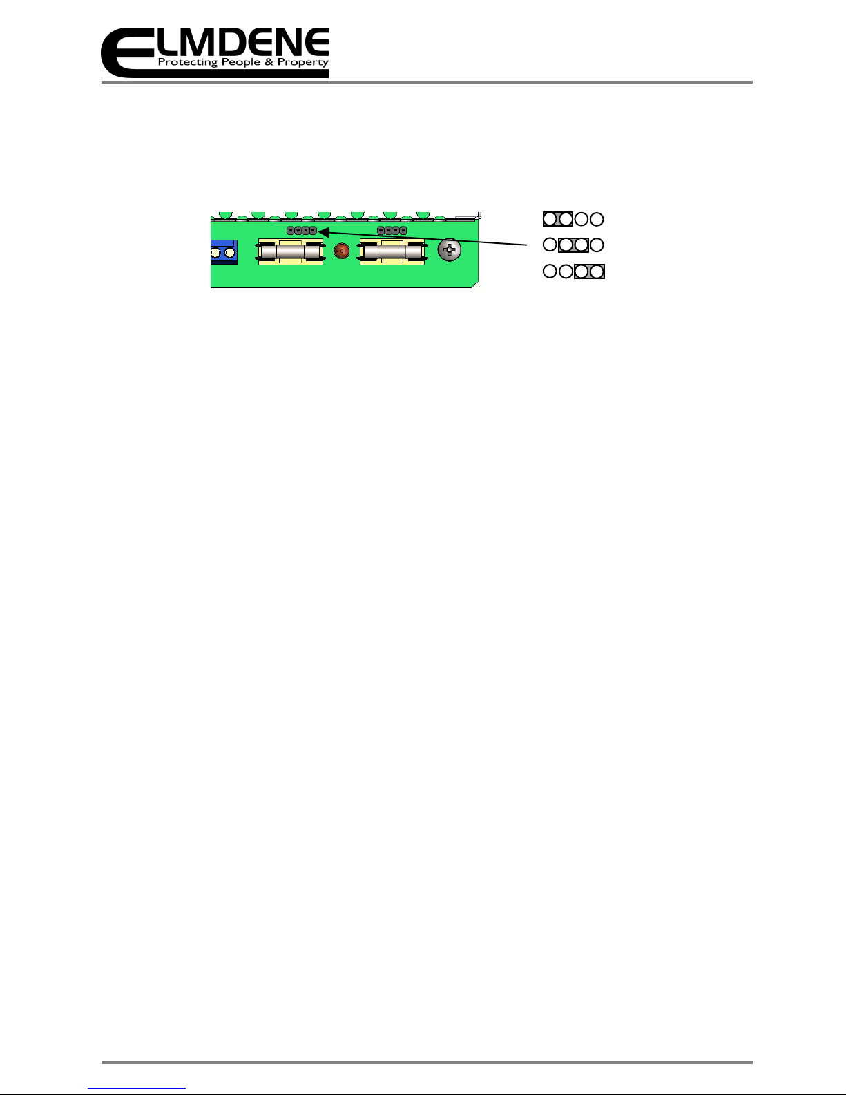
10) Select the Battery type by placing the link (above the Battery fuse) in the appropriate location to
select (17/18 Ah, 38 Ah or 65 Ah) batteries. This changes the maximum bulk charge current, and
therefore enables higher load current to be used when smaller batteries are required. Put the link
on the left hand two pins for 17/18 Ah, the middle pins for 38 Ah and the right hand two pins for 65
Ah batteries.
Figure 6 – Standby battery size selection links
11) Mount the appropriate batteries as shown above. Where a dual box solution is used all cabling
between the two boxes should be routed to use separate case entry/exit holes from other cabling
and use suitable bushes to protect the cables.
12) Connect the two 12 V standby batteries in series using the single cable provided. Connect the
negative of one battery to the positive of the other. DO NOT CONNECT the other two battery
terminals to each other.
13) Connect the free Positive and Negative terminals of the batteries to the PCB terminals Batt+ and
Batt - using the cables provided. See Figures 4 & 5.
14) Connect the battery temperature sensor (two white wires) to the PCB terminals TMP Sens. See
Figure 5.
15) If the batteries are housed remotely, replace the battery lead assembly (including battery
temperature sensor) with an extended length assembly, provided with the Battery box (Ensure the
temperature sensor and battery connections are made according to figure 5.
16) Re-apply the mains power and verify that the yellow Fault LED stops flashing after about 20 s
(battery connection detected). Verify that the remote GEN PSU Fault monitor shows a closed
contact.
17) Disconnect the mains power. Verify that the green Mains LED extinguishes and the yellow Fault LED
starts to pulse (indicating that the PSU is running from its standby batteries).
18) If connected, verify that the EPS Fault monitor shows an open contact and the PSU Fault monitor
shows a closed contact.
19) Perform a full functional test of system including full alarm condition. Verify that the standby
batteries can support the system load. Note: ensure batteries have sufficient charge.
Final
20) Reconnect the mains. Verify that the green Mains LED illuminates and the yellow Fault LED
extinguishes.
21) If connected, verify that the EPS Fault monitor shows a closed contact and the GEN PSU Fault
monitor shows a closed contact.
22) Close cover and secure using fastening screws provided.
17/ 18 Ah
38 Ah
65 Ah

9
Technical Support: +44(0)23 9269 6638 (option 3) PAK200574_01K May 2016 ©2016 ELMDENE INTERNATIONAL LTD
O
PERATING INSTRUCTIONS
In the event of loss of mains, a battery fault or a GEN fault, the corresponding Fault signal contacts will open.
If the output of the PSU fails, the cause of the failure should be investigated e.g. short circuit load,
connection of a deeply discharged battery. The fault should be rectified before restoring power to the PSU. If
any of the fuses require replacing, ensure the correct fuse rating and type is used.
M
AINTENANCE
Maintenance
This unit is intended for use by Service Personnel only. There are NO USER SERVICEABLE parts inside.
There is no regular maintenance required of the PSU other than periodic testing, and replacement of the
standby battery. Reference should be made to the battery manufacturer's documentation to determine
typical/expected battery life with a view to periodic replacement of the battery.
D
IAGNOSTICS
Local Diagnostics
Green LED On = Mains Present
Yellow LED Fault Diagnostics according to table:
Yellow LED
(fault)
Green LED
(mains)
Status
OFF ON Normal: Battery fully charged
One short flash
every second
ON Normal: Battery charging but not fully charged
Flashing:
1second On
1 second Off
ON
Fault:
Output fuse or battery fuse blown, or
battery missing
OFF Fault: No mains, output fuse blown
One short flash
every 3 seconds
OFF Fault: No mains, battery supplying load.
OFF OFF
Fault:
No mains
, No output
, Batteries
disconnected or completely discharged
10
Technical Support: +44(0)23 9269 6638 (option 3) PAK200574_01K May 2016 ©2016 ELMDENE INTERNATIONAL LTD
C
OMPLIANCE
This power supply unit meets the essential requirements of the following EU Directives:
CPR: 305/2011 EU EMC: 2014/30/EU Low Voltage: 2014/35/EU WEEE: 2012/19/EU RoHS2: 2011/65/EU
Functional standard: EN54-4:1997 +A1 +A2
Environmental Class II
Certification Body: Underwriters Laboratory
Declaration of Performance DOP2014/08
DOP2014/09
D
ISPOSAL OF PRODUCT AT END OF LIFE
This product falls within the scope of EU Directives 2012/19/EU Waste Electrical and Electronic Equipment
(WEEE) and 2013/56/EU (Battery). At the end of life, the product must be separated from the domestic
waste stream and disposed via an appropriate approved WEEE disposal route in accordance with all national
and local regulations.
Before disposal of the product, any batteries must be removed, and disposed separately via an appropriate
approved battery disposal route in accordance with all national and local regulations. Package used batteries
safely for onward transport to your supplier, collection point or disposal facility.
Caution: Risk of fire or explosion
if bare battery wires are allowed to touch.
See Specification for battery type information. The battery is marked with the crossed out wheelie bin
symbol, which may include lettering to indicate cadmium (Cd), lead (Pb), or mercury (Hg).
For more information see: www.recyclethis.info
The packaging supplied with this product may be recycled.
Please dispose of packaging accordingly.
0843
Elmdene International Ltd 3 Keel
Close Portsmouth PO35QD
14
0843-CPR-0216
EN54-4:1991997 +A1 +A2
Power Supplies intended for use in
fire detection and fire alarm
 Loading...