

ELM ELM382SM, ELM382P Datasheet
ELM382
1234876
5
Description
50 Hz Long Interval Counter
5
4
6
Features
The ELM382 is a digitally configurable, multistage counter circuit in a single 8 pin package. When
connected to a 50Hz source, four time periods from
one hour to one week are possible, as shown in
Table 1 below.
Although the circuit has been optimized for a
50Hz input frequency, it is capable of being operated
over a very wide range of frequencies. Of particular
interest is the ability to interface directly to very low
frequencies with varying waveforms due to the use
of a Schmitt trigger input circuit.
The ELM382 provides two outputs – a standard
50% duty cycle divider output, and a momentarily
pulsed output. The pulse output is useful for audibly
or visually signalling the beginning of a time period,
or as a trigger for other circuitry. Refer to the
Example Applications section for two typical circuits.
Applications
• Long term (daily or weekly) event timers
• Missing event detectors
• Automatic shutoff circuits
• Low power CMOS design - typically 1mA at 5V
• Wide supply range – 3.0 to 5.5 volt operation
• Digitally selectable delays
• Schmitt trigger circuitry on the clock input
• Completely static operation
• Long term accuracy with line frequency clock
• High current drive outputs – up to 25 mA
• Reset input provided with a pullup resistor
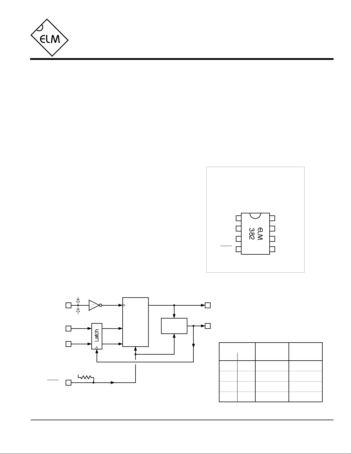
Connection Diagram
PDIP and SOIC
(top view)
VDD VSS
D1
D0
Out
Pulse
Clockreset
Block Diagram
Clock
2
D1
3
D0
reset
ELM382DSA
VDD
VSS
VDD
7
Out
Digital
Counters
Pulse
Generator
Pulse
Setting Divisor
D1
L
L
H
H
Elm Electronics – Circuits for the Hobbyist
< http://www.elmelectronics.com/ >
D0
L
H
L
H
x 1000
180
2160
4320
30,240
Table 1
Period
(50Hz)
1 hour
12 hrs
24 hrs
7 days
1 of 4

ELM382
Pin Descriptions
VDD (pin 1)
This pin is the positive supply pin, and should
always be the most positive point in the circuit.
Internal circuitry connected to this pin is used to
provide power on reset of the microprocessor, so
an external reset signal is normally not required.
Refer to the Electrical Characteristics section for
further information.
D1 (pin 2) and D0 (pin 3)
The logic levels on these pins control the divider
ratio, as shown in Table 1. Their levels are stored
in an internal latch on the low to high transistion of
the Pulse output, and are used for that entire
timing period.
reset (pin 4)
An active low input that forces both outputs low,
and causes all counter stages to initialize. If
unused, it can be left open circuited (due to the
internal resistor) or preferrably tied to VDD. Refer to
the minimum timing requirements in the Electrical
Characteristics section.
present. The Schmitt trigger amplifier on the
input simplifies the coupling to slowly varying
signals, while the inherent protection diodes
(shown in the block diagram) allow signals with
peak levels beyond the supply limits to be
connected through a current limiting resistor.
Pulse (pin 6)
This output pin is normally at a low level, but is
momentarily driven high at the beginning of
every timing period. The duration of the pulse is
fixed at 50 cycles of the clock input (nominally 1
second with a 50Hz input). This output will not
assume a high level following a circuit reset until
there has been a valid clock transition.
Out (pin 7)
This is the main timing chain output. It has a
fixed 50% duty cycle, and begins each timing
cycle at a logic low level. Halfway through each
cycle, Out will assume a logic high level and will
remain high until the end of the timing period.
Clock (pin 5)
The counter stages advance on the falling edge
(VDD to VSS) of this input, if there is no reset signal
VSS (pin 8)
Circuit common is connected to this pin. This is
the most negative point in the circuit.
Ordering Information
These integrated circuits are available in either the 300 mil plastic DIP format, or in the 200 mil SOIC surface
mount type of package. To order, add the appropriate suffix to the part number:
300 mil Plastic DIP............................... ELM382P 200 mil SOIC.....................................ELM382SM
All rights reserved. Copyright ©2000 Elm Electronics.
Every effort is made to verify the accuracy of information provided in this document, but no representation or warranty can be
given and no liability assumed by Elm Electronics with respect to the accuracy and/or use of any products or information
described in this document. Elm Electronics will not be responsible for any patent infringements arising from the use of these
products or information, and does not authorize or warrant the use of any Elm Electronics product in life support devices and/or
systems. Elm Electronics reserves the right to make changes to the device(s) described in this document in order to improve
reliability, function, or design.
ELM382DSA
Elm Electronics – Circuits for the Hobbyist
< http://www.elmelectronics.com/ >
2 of 4
 Loading...