

ELM ELM331P, ELM331SM Datasheet
ELM331
1234876
5
Solid State Thermostat
23467
5
Description
Features
The ELM331 is a complete temperature
measurement and control system in an 8 pin
package.
This integrated circuit is designed to compare
two resistances and drive an output pin depending
on the relative value of each. Typically, one of the
resistors will be an NTC thermistor, and the other
one will be a temperature independent resistor
(whether fixed or variable). When the magnitude of
the resistance connected to pin 2 exceeds the value
of the resistance connected to pin 3, the output pin
will be driven to a high state. Hysteresis maintains
the output in that state until the relative values differ
by approximately 8% (or typically 2°C for a 10KΩ
thermistor).
To reduce the possibility of sporadic outputs, a
condition must exist for three successive cycles, or 6
seconds, before the output pin can change state.
Applications
• Primary thermostat in temperature control
systems
• Staging control for auxiliary heating or cooling
installations
• Under or over temperature alarms
• Low power CMOS design - typically 1mA at 5V
• Wide supply range - 3.0 to 5.5 volt operation
• Built-in proportional hysteresis
• Measurement in progress output
• Time delay on operate improves noise immunity
• Internal pullup resistor on the reset input
• High current drive outputs - up to 25 mA
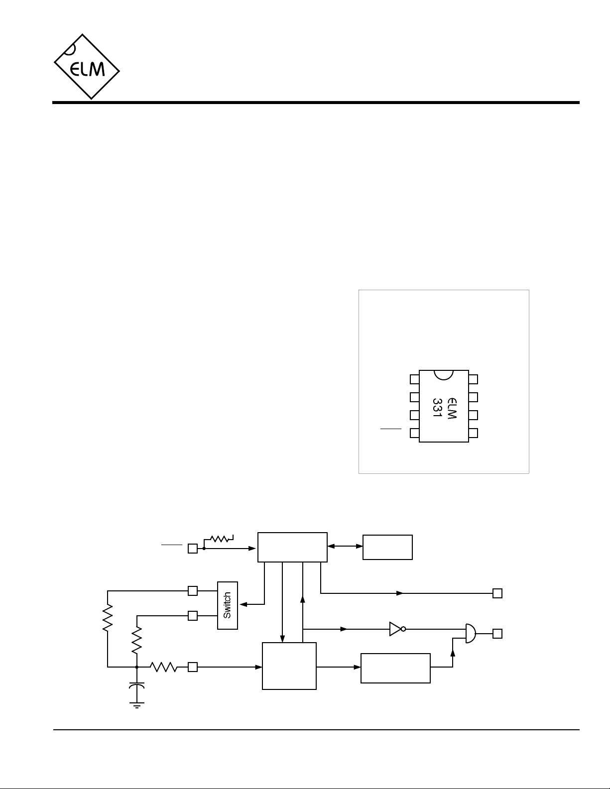
Connection Diagram
PDIP and SOIC
(top view)
VDD VSS
OutR1
R2
reset
MIP
Cap
Block Diagram
VDD
Control
Analog to
Digital
Converter
Overrange
R1 > R2
R1
ELM331DSB
reset
R2
Elm Electronics – Circuits for the Hobbyist
< http://www.elmelectronics.com/ >
Watchdog
Timer
Measurement in Progress (busy)
3 Consecutive
Measurements
MIP
Out
1 of 4

ELM331
Pin Descriptions
VDD (pin 1)
This pin is the positive supply pin, and should
always be the most positive point in the circuit.
Internal circuitry connected to this pin is used to
provide power on reset of the microprocessor, so
an external reset signal is normally not required.
Refer to the Electrical Characteristics section for
further information.
R1 (pin 2)
One of the two resistance input pins. A
temperature dependent resistance is usually
connected to this input for heating or undertemperature alarm type applications. When the
value of this resistor is greater than the value of
the resistance connected to pin 3 (for three
successive measurements) the output will be
driven high.
R2 (pin 3)
The reference resistance is connected to this pin
for heating applications, and the temperature
dependent resistance is connected here for
cooling applications. The other end of this resistor
is connected to the integrating capacitor.
Cap (pin 5)
Temperature measurements are made by
determining the time to charge and discharge this
integrating capacitor. Pin 5 forces the capacitor to
a known voltage for these measurements though,
resulting in large current flows. To limit these
capacitor currents, and protect the ELM331, a
series resistor must be connected to this pin. The
value of the resistance, and of the capacitance, is
not critical to the measurements.
MIP (pin 6)
This pin provides a logic high level output while
the ELM331 is busy (measurements are in
progress). It is suitable for directly driving an LED
through a current limiting resistor. As a warning,
this output pulses rapidly if either resistor input is
found to be open circuited.
Out (pin 7)
The output pin assumes a logic high state once
the resistance of R1 exceeds that of R2 for three
successive measurement cycles. The output is
maintained until R1 is less than R2 by the
hysteresis amount for an additional three counts.
reset (pin 4)
The active low reset input. An internal pullup
resistor is provided for convenience. If unused,
this pin may be connected to VDD or left open.
VSS (pin 8)
Circuit common is connected to this pin. This is
the most negative point in the circuit.
Ordering Information
These integrated circuits are available in either the 300 mil plastic DIP format, or in the 200 mil SOIC surface
mount type of package. To order, add the appropriate suffix to the part number:
300 mil Plastic DIP............................... ELM331P 200 mil SOIC.....................................ELM331SM
All rights reserved. Copyright ©1999 Elm Electronics.
Every effort is made to verify the accuracy of information provided in this document, but no representation or warranty can be
given and no liability assumed by Elm Electronics with respect to the accuracy and/or use of any products or information
described in this document. Elm Electronics will not be responsible for any patent infringements arising from the use of these
products or information, and does not authorize or warrant the use of any Elm Electronics product in life support devices and/or
systems. Elm Electronics reserves the right to make changes to the device(s) described in this document in order to improve
reliability, function, or design.
ELM331DSB
Elm Electronics – Circuits for the Hobbyist
< http://www.elmelectronics.com/ >
2 of 4
 Loading...