

ELM304
1234876
5
NTSC Video Generator
Description
23467
5
Features
The ELM304 is a low-cost NTSC video signal
generator in an 8 pin package. Requiring only an
external crystal and a few passive components, this
circuit produces a stable raster that is suitable for a
variety of video applications.
The ELM304 can be ‘programmed’ to generate
either a solid white raster or a four-level gray scale
pattern simply by changing the logic level at the
mode input pin. A supplied internal pullup resistor
further simplifies the circuitry when interfacing to
mechanical switches.
Although originally designed to provide a stable
video input signal for use while recording audio on
video cassette recorders, this circuit can also be
used for many other instructional and test purposes.
The low power consumption and small size of the
circuit also makes it ideal for battery-powered
applications.
Applications
• Video Source for Video Cassette Recorders
• Classroom Instructional Aid
• Test Bench Video Generator
• Low power CMOS design - typically 1mA at 5V
• Wide supply range - 3.0 to 5.5 volt operation
• Uses a standard 3.58MHz crystal
• Generates both solid and bar type patterns
• No external amplifier required
• Standard 1V p-p NTSC sync negative output
• Requires no adjustments
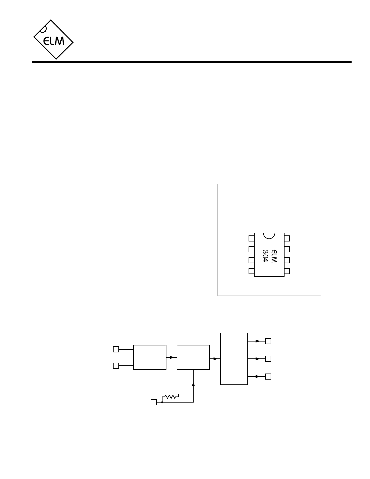
Connection Diagram
PDIP and SOIC
(top view)
VDD VSS
V1XT1
XT2
Mode
V2
V3
Block Diagram
V1
XT1
XT2
ELM304DSB
Master
Oscillator
Mode
Pattern
Generator
VDD
Output
Matrix
Elm Electronics – Circuits for the Hobbyist
< http://www.elmelectronics.com/ >
V2
V3
1 of 4
ELM304
Pin Descriptions
VDD (pin 1)
This pin is the positive supply pin, and should
always be the most positive point in the circuit.
Internal circuitry connected to this pin is used to
provide power on reset of the microprocessor, so
an external reset signal is not required. Refer to
the Electrical Characteristics section for further
information.
XT1 (pin 2) and XT2 (pin 3)
A 3.579545MHz NTSC television colourburst
crystal is connected between these two pins.
Crystal loading capacitors (typically 27pF) will
also normally be connected between each of the
pins and Vss.
Mode (pin 4)
The ELM304 can be selected to operate in one of
two modes depending on the logic level on this
pin. When at a high level (or open-circuited), the
generated raster is solid white in colour. If this pin
is held at a low level, the circuit will generate a
four-level pattern of typically 100%, 60%, 40%
and 20% white.
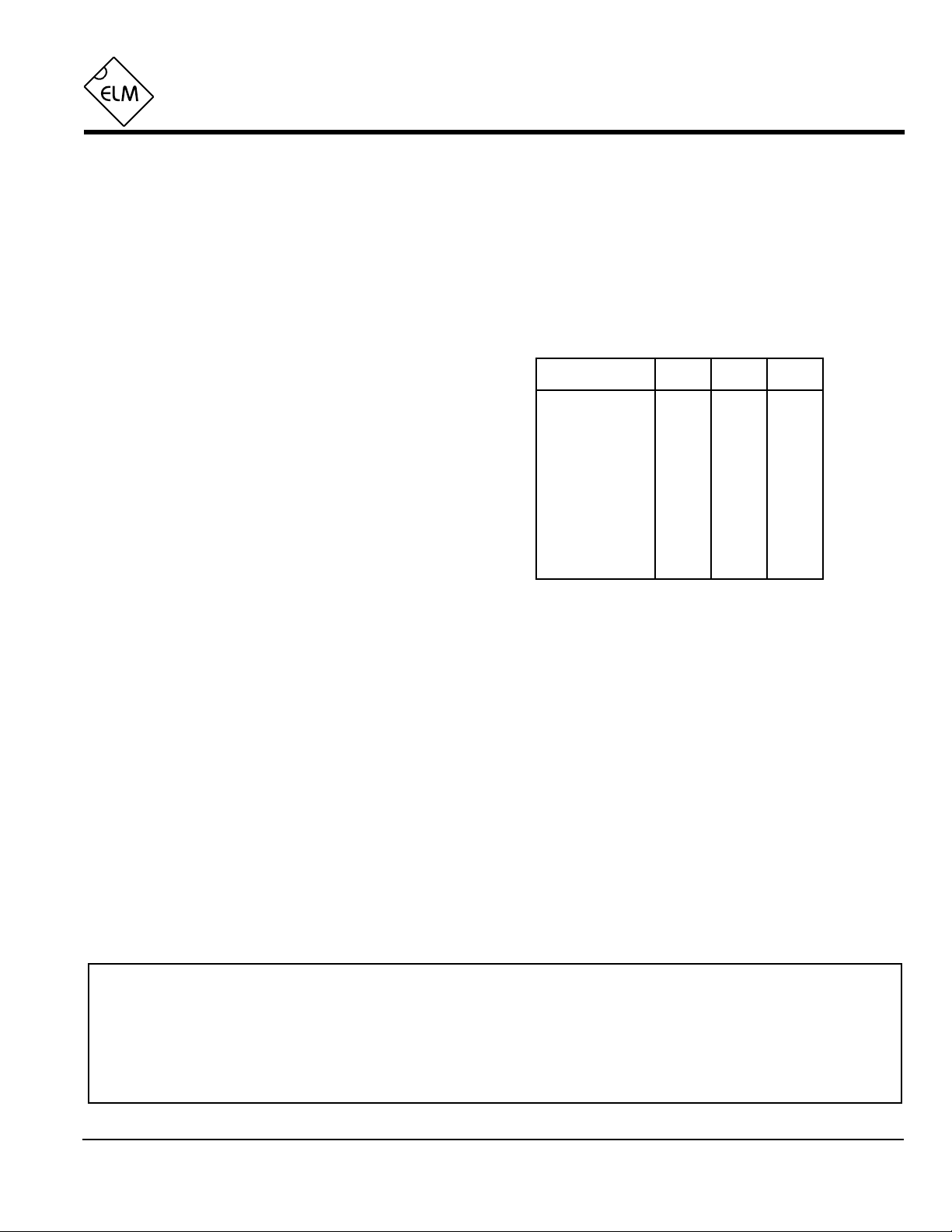
V3, V2, and V1 (pins 5, 6, and 7)
These are the digital to analog converter’s logic
level output signals. When combined through a
few appropriate resistors (see the example
application section), a standard 1Vp-p NTSC
video signal is created. Output levels during the
signal phases are as follows:
Signal Phase
Sync
Blanking
20% White
40% White
60% White
100% White
V3 V2 V1
L L L
L L H
H L L
L H H
H L H
H H H
VSS (pin 8)
Circuit common is connected to this pin. This is
the most negative point in the circuit.
Ordering Information
All rights reserved. Copyright ©1999 Elm Electronics.
Every effort is made to verify the accuracy of information provided in this document, but no representation or warranty can be
given and no liability assumed by Elm Electronics with respect to the accuracy and/or use of any products or information
described in this document. Elm Electronics will not be responsible for any patent infringements arising from the use of these
products or information, and does not authorize or warrant the use of any Elm Electronics product in life support devices and/or
systems. Elm Electronics reserves the right to make changes to the device(s) described in this document in order to improve
reliability, function, or design.
ELM304DSB
These integrated circuits are available in either the 300 mil plastic DIP format, or in the 200 mil SOIC surface
mount type of package. To order, add the appropriate suffix to the part number:
300 mil Plastic DIP............................... ELM304P 200 mil SOIC.....................................ELM304SM
Elm Electronics – Circuits for the Hobbyist
< http://www.elmelectronics.com/ >
2 of 4

ELM304
Absolute Maximum Ratings
Stresses beyond those listed here will likely damage
the device. These values are given as a design
guideline only. The ability to operate to these levels
is neither inferred nor recommended.
Storage Temperature.......................-65°C to +150°C
Note:
Ambient Temperature with
Power Applied....................................-40°C to +85°C
Voltage on VDD with respect to VSS............0 to +7.5V
Voltage on any other pin with
respect to VSS........................... -0.6V to (VDD + 0.6V)
Electrical Characteristics
All values are for operation at 25°C and a 5V supply, unless otherwise noted. For further information, refer to note 1 below.
Characteristic Minimum Typical Maximum ConditionsUnits
Supply Voltage, VDD 3.0 5.0 5.5 V
VDD rate of rise 0.05 V/ms
Average Supply Current, IDD 1.0 2.4 mA
Input low voltage VSS 0.15 VDD V
Input high voltage VDD V0.85 VDD
see note 2
see note 3
Internal pullup resistance (pin 4) 300 500 600 KΩ
Output low voltage 0.6 V
Output high voltage VVDD - 0.7
Timing accuracy 0.25 %
Notes:
1. This integrated circuit is produced with a Microchip Technology Inc.’s PIC12C5XX as the core embedded
microcontroller. For further device specifications, and possibly clarification of those given, please refer to the
appropriate Microchip documentation.
2. This spec must be met in order to ensure that a correct power on reset occurs. It is quite easily achieved
using most common types of supplies, but may be violated if one uses a slowly varying supply voltage, as
may be obtained through direct connection to solar cells, or some charge pump circuits.
3. Device only. Does not include any current supplied to external circuits.
4. The value of the internal pullup resistance is both supply and temperature dependent.
5. This assumes that the recommended 3.58MHz crystal is used.
see note 4
Current (sink) = 8.7mA
Current (source) = 5.4mA
see note 5
ELM304DSB
Elm Electronics – Circuits for the Hobbyist
3 of 4
< http://www.elmelectronics.com/ >

Example Application
ELM304
1234876
5
The ELM304 is typically used in a circuit such
as the one shown in Figure 1 below. The type of
application determines the supply used – if an AC
type supply is available, 5V is likely to be the best
choice, but battery operation is also a good
alternative. Typical current drain for this circuit is
only about 10mA at 3V for the bar pattern, and
13mA for the white. At this rate AAA type alkaline
batteries are likely to last about 30hrs while AA
alkalines should provide closer to 100hrs of service.
Once the power supply voltage is determined,
the values of the summing resistors are chosen
using Table 1 as a guideline. Depending on the
accuracy desired, some trimming of the values
may be required, but these values are likely to
provide satisfactory levels for most applications.
Finally, the required type of output pattern
should be determined. If it is desirable to be able to
change patterns ‘on the fly’, a switch connected as
shown is likely required, but if only one pattern is
required, the Mode input can be connected directly
to VDD (white) or VSS (bars).
When testing, keep in mind that the output
voltage varies directly with loading. Resistor
values shown assume a load resistance of 75Ω
connected to the output, and if this is not present,
levels will be considerably higher than the 1V p-p
that is expected.
As always, good wiring practices should be
followed when wiring this circuit. In this case
ringing on the supply lines, stray capacitance, etc.
are likely to result in visible problems however, so
take a little extra care.
3V 5V
R1
R2
R3
330Ω
330Ω
220Ω
680Ω
680Ω
430Ω
27pF
3.58MHz
27pF
VDD
0.1µF
Mode – switch
closed for bars,
open for white
Figure 1. Typical Circuit Configuration
R4
Table 1 Typical Resistor Values
R1
R2
R3
470Ω
R4
150Ω
75Ω (unbalanced)
video signal
ELM304DSB Elm Electronics – Circuits for the Hobbyist
< http://www.elmelectronics.com/ >
4 of 4
 Loading...