

Surgitron
®
F. F. P. F. E M C
TM
Quality Record and Maintenance
Manual
Cat. No. EMCMM10


3
Surgitron
®
F. F.P. F. E M C
TM
CONTENTS
I. DECLARATION OF CONFORMITY 4
1.1 Declaration of Conformity
II. QUALITY RECORD 5
2.1 General
2.2 First Degree Inspection
2.3 Second Degree Inspection
2.4 Output Power Characteristic
2.5 Output Power Characteristic
III. MAINTENANCE & TROUBLE SHOOTING 9
3.1 Surgitron System Block Diagram
3.2 Basic Circuit Diagrams
3.3 Repair Kit

4
I. DECLARATION OF CONFORMITY
Application of Council Directive: Medical Device Directive (93/42/EEC)
Standards to Which Conformity is Declared:
1. Conforms to the immunity requirements of EN 60601-1-2
2. Conforms to the emissions requirements of EN 60601-1-2 and EN 60601-2-2
For technical support, telephone 516-594-3333 or 800-835-5355,
Fax 516-569-0054, or email ellman@ellman.com
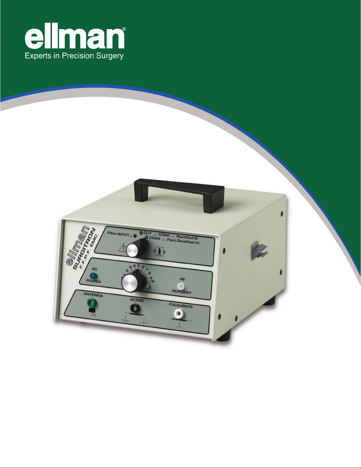
Congratulations on your purchase of Ellman International’s radiosurgical device, the Surgitron®F.F.P.F. EMC™.
ellman®International is the leader in the field of Radiosurgery®. Our innovations, 25+ U.S. Patents, and
commitment to our proven record of safety and superior performance is documented in numerous clinical articles
and textbooks in the specialties of otolaryngology, ophthalmology, gynecology, dermatology, family practice,
plastic surgery, general surgery, podiatry, and neurosurgery.
Be assured that you are testing the safest, most reliable high-frequency radiosurgical instrument available.
The following technical and safety information is provided to assist you, the bio-medical engineer, in a thorough,
trouble-free performance verification and safety inspection of the Surgitron®F.F.P.F. EMC™.
If you require additional information or have any questions or comments regarding this device, feel free to
contact ellman®International.

5
II. QUALITY RECORD
ellman International, Inc.
3333 Royal Avenue, Oceanside, NY 11572 U.S.A
tel: (800) 835-5355, (516) 594-3333, fax: (516) 569-0054
2.1 GENERAL
a. Model:______________________________________
b. Serial Number:______________________________
c. Power Supply Voltage:_______________________
d. Thermo Transformer Type: MAGNET WOUND
2.2 FIRST DEGREE INSPECTION Inspector:___________________________ Date:________________
(Refer to the 500 ohm load output power curve with 20% tolerance.)
Test equipment: Tektronics DPO 4032, Tektronics Probe P5100, 500 ohm Non-Inductive Load, DMM.
1. Operating Modes Inspection (Waveform inspection) and Primary Output Inspection
a. CUT:__________(Check waveform with oscilloscope: Pure Filtered Wave)
Dial # 1 23456789Hi
Power
b. CUT COAG:________(Check waveform with oscilloscope: Fully Rectified)
Dial # 1 23456789Hi
Power
c. COAG:________(Check waveform with oscilloscope: Partially Rectified)
Dial # 1 23456789Hi
Power
d. FULGURATE:_____(Only an oscilloscope is to be used for this measurement: Spark-Gap)
Dial # 1 23456
Power
ROOM TEMP.: ____°F ROOM HUMIDITY: ____%

6
2. Hardware Inspection: (Visual Inspection)
a. Paint Finish Pass_________ Fail________
b. Labeling Pass_________ Fail________
Inspector: _____________ Date: ______
2.3 SECOND DEGREE INSPECTION
This test is according to UL544 Standard.
Test equipment: HIPOT tester,
1. Dielectric Withstand Inspection: Pass_________ Fail________
2. Ground Continuity Inspection: Pass_________ Fail________
3. Work Bench Practical Test: Pass_________ Fail________
20 Mins @ 10 sec.
On/ 30 sec. Off
Inspector: _____________ Date: ______

7
2.4 OUTPUT POWER CHARACTERISTIC

8
2.5 OUTPUT POWER CHARACTERISTIC

9
III. MAINTENANCE & TROUBLE SHOOTING
The system block diagram and basic circuit schematic are provided here for general review of the basic circuits
that make up the Surgitron®FFPF EMC™. They should be reviewed carefully before performing any
troubleshooting. Troubleshooting flowcharts are supplied for the more common problems.
The power supply includes the entry module, thermal transformer, fuses and line switch. Four high-power diodes
make up the full wave rectifier. The mode selector controls the output waveform rectifier and filter. There are
three options from the mode selector:
1. Fully rectified and filtered
2. Fully rectified
3. Partially rectified
They are used to perform pure Cut, Cut and Coag, and Hemo, respectively.
The RF signal network generates a 3.8 MHz high frequency signal as a carrier. This is modulated by the lower
frequency signal from the mode selector.
The output power supply controller controls the output impedance matching and, therefore, controls the power
output. Power output vs. load impedance test curves are included for your reference, see Fig. 3. This power
intensity curve is plotted with a 500 Ohm pure resistance load.
The antenna plate provides the return path for the RF signal. The system output is controlled by operating the
footswitch.
The following fault conditions are defined, along with the check procedure and the specific conditions
experienced. Step-by-step procedures necessary to isolate the fault are provided so that solutions are
achieved.
A. If red AC light does not light up:
1. Check that the power cord is plugged into the wall outlet and the other end is correctly
plugged into the receptacle unit.
2. Check fuses; do not use larger than indicated – 1.6 amp/220V or 3.0 amp/117V. Using a
larger fuse will damage the Surgitron unit. Replace fuse with P/N: R-EK03A (1.6 amp/220V) or
R-EK03B (3.0 amp/117V), as specified in the Surgitron FFPF EMC Repair Kit.
3. If fuse continues to blow, remove four screws from both sides of the unit and carefully remove cover.
Check for the following conditions:
a. Transformer short circuit – replace P/N R-EK09 (RF Safety Thermo Transformer).
b. Check short circuit on diode PCB or replace P/N R-EK13.
c. Check short circuit on R1 or replace P/N R-EK15.
d. Check short circuit on R5 or replace P/N R-EK16.
4. Check AC indicator bulb; if it is open-circuited, replace P/N R-EK05A (AC Light Diode). Check the
voltage output of the power entry module. If there is no voltage, replace the power entry module,
R-EK17.
5. Check secondary output voltage from transformer:
a. Between green wires should be >6.3V.
b. Between red wires should be >600V.
c. If these conditions are not met, replace P/N R-EK09 (RF Safety Thermo Transformer).
6. Visually inspect the unit for shorted or burnt resistors and capacitors. Inspect wire connections and
solder joints.
7. Tube may be defective; replace P/N R-EK10 (RF Amplifier Power Tube).

10
B. If RF indicator does not light when foot-switch is pressed:
1. Allow a 15 second warm-up period before activating the unit.
2. Defective foot-switch; replace with P/N R-EK2 (EMC RF Foot Control).
3. Turn on the unit and allow a 15 second warm-up period. Visually inspect tube filament. If it does not
glow (and AC indicator light is on), replace with P/N R-EK10 (RF Amplifier Power Tube).
4. Check RF light bulb. If it is open-circuited, replace with P/N R-EK14.
5. Check ground system to see if green/yellow ground wire is connected. This wire must be attached to
chassis ground.
6. Check shorted or burnt components on R-EK16. If there is problem, replace R-EK16.
Transformer Wiring
220 VAC - the Black and the White transformer primary wires should be used.
110/120 VAC - the Black and the Black/Red transformer primary wires should be used.
100 VAC - the Black and the Black/white transformer primary wires should be used.

11
3.1 SURGITRON SYSTEM BLOCK DIAGRAM

3.2 BASIC CIRCUIT DIAGRAM
12

13
3.3 SURGITRON F.F.P.F. EMC REPAIR KIT
Item Description
R-EK01A Black RF Function Selector Knob
R-EK01B Black RF Power Control Knob
R-EK02 EMC RF Foot Control
R-EK03 3.0 Amp EMC RF Safety Fuse, 117v
R-EK03B 1.6 Amp EMC RF Safety Fuse, 220v
R-EK04A Green Female Connector
R-EK04B Black Female Connector
R-EK04C White Female Connector
R-EK05A AC Light Diode
R-EK05B RF Light Diode
R-EK06A Green AC Light Cap
R-EK06B White AC Light Cap
R-EK07 RF Insulated Power Control
R-EK08 RF Inductor Coil 17uH
R-EK09 RF Safety Thermo Transformer, 700v
R-EK09/7A RF Safety Thermo Transformer, 700v w/Audio
R-EK10 RF Amplifier Power Tube
R-EK11 PC Board, EMC-A, Main Board
R-EK12 PC Board, EMC-B, 2-Gang + R4 Board
R-EK13 PC Board, EMC-C, Rectifier Board
R-EK14 PC Board, EMC-D, R6 & R7 Resistor Board
R-EK15 PC Board, EMC-E, 4-Gang
R-EK16 PC Board, EMC-F
R-EK17 AC Power Entry Module
R-EK18A EMC RF Enclosure - Base
R-EK18B EMC RF Enclosure - Cover
R-EK19A EMC Handle, Black
R-EK20 Silicone Rubber Feet (pkg of 4)
R-EK21 RF Waveform Rotary Switch
R-EK22 Hospital-grade RF Power Cord
R-EK23 Audio Board

NOTES
14

15

DIM-18-81 A
ellman International Inc.
3333 Royal Avenue,
Oceanside, N.Y. 11572-3625 U.S.A.
Tel: 800 835-5355 • 516 594-3333
Fax: 516 569-0054 • www.ellman.com
EU Representatives:
ellman UK
16 Ryehill Court, Lodge Farm,
NN57EU Northampton
Tel: 44-1064-589-928
Fax: 44-1604-759-096
 Loading...