

Elliwell EWDR 72 General Description Manual
GENERAL DESCRIPTION
The EWDR 72 has been designed specifically to be used as defrost timer in refrigeration systems.
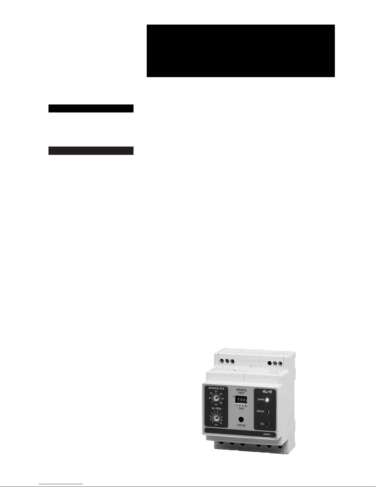
The EWDR 72 comes in a 4-module DIN
housing suitable for DIN-rail mounting. As
with the EWTS 70, it controls the intervals
between defrost cycles (adjustable from
2 to 30 hours, in 2 hour increments) as well
as the duration of the defrost (from 1 to 60
minutes).
Likewise, the defrost output can also be
controlled by a klixon-type device (not
supplied); in addition, a button is provided
on the front panel to perform a manual defrost. The EWDR 72 also provides fan cutout during the defrost as well as restart of
the fan subject to a time delay (adjustable
with a trimmer).
The adjustment of times and temperatures
is extremely easy as it is obtained by
means of mini trimmers indicating the setting and mini switches which are selectable according to a table printed on the
instrument itself. On its front side a series
of leds permits the read-out of the running
cycle (normal defrost, fan delay).
This defrost timer provides an esthetical
match with the corresponding ELIWELL
temperature controllers, i.e. EWDR series
(DIN-rail mount). The combination of an
ELIWELL defrost timer and an ELIWELL
temperature control provides a comprehensive and easy to operate modular control system which fits attractively in any
modern refrigeration or freezer unit.
PANEL LAY-OUT AND SYSTEM
SET-UP
“POWER” led: green “power on” light.
“DEFROST” led: red “defrost in progress”
light.
“FANS” led: green status light for the
fan(s): it stays on to indicate that the fan is
running; it flashes when the fan is in a delay-before-start mode (i.e. after a defrost).
“DEFROST INTERVAL” dip-switches
(1, 2, 3 and 4): to select the time interval
between the defrost cycles. The required
setting is achieved by adding the values
assigned to each of these 4 dip-switches.
For instance, by setting only switch 1 (value = 2) at “ON”, the defrost frequency is 2
hours; a 6-hour frequency is achieved by
setting switches 1 and 2 in the “ON” position, with 3 and 4 in “OFF”.
“DEFROSTING TIME” trimmer: screwdriver operated slotted trimmer for the setting, in minutes, of the desired length of a
defrost cycle.
“FAN DELAY TIME” trimmer: screwdriver operated slotted trimmer to set the time
delay (in minutes) for the fan, after a defrost
cycle or after system start-up.
“MANUAL” button: pushbutton to start a
defrost cycle manually.
OPERATION
The green ”POWER” status light will come
on as soon as power is connected to the
instrument. The fan remains off according
to the selected fan time delay which is indicated by the flashing green “FANS” led.
After this time delay the fan is started and
the green “FANS” light stops flashing
(stays on steady).
A timed defrost cycle is started automatically: the corresponding relay is energized,
provided however that the klixon input is
closed (install a jumper if this input is not
HOW IT IS MADE
• Housing material: self-extinguish
ABS plastic
• Dimensions: 4-module DIN,
70x85 mm front
• Mounting: on DIN-rail (omega 3)
or wallmount
• Connections: terminal block for
max 2.5 mm
2
wiring
• Defrost frequency: from 2 to 30
hours, in 2-hour increments
• Length of defrost: from 1 to 60
minutes
• Klixon-type input: terminals for remote klixon signal (for temperature termination)
• Manual defrost: push-button provided
• Defrost output: SPDT relay 8(3)A
250V AC
• Fan delayed start: adjustable between 1 and 10 minutes
• Fan control output: SPDT relay
8(3)A 250V AC
• Power absorption: 160 mA max
• Power supply: 220/110 Vac,
50/60 Hz or 12 Vac/dc. Others on
request
WHAT IT IS
The EWDR 72 has been designed
specifically to be used as defrost
timer in refrigeration systems.
EWDR 72
rel. 9/96 ing
defrost timer DIN rail
2EWDR 72 9/96 ing
used). At this time, the red “DEFROST” led
will come on to indicate that a defrost is in
progress. The green “FANS” led will go out
to indicate thet the fan has been turned off
during the defrost. The defrost cycle is terminated as soon as the programmed time
period has lapsed (the “time-out”), or when
the klixon reaches the termination temperature.
It is also possible to start a manual defrost
cycle at any time simply by pressing the
appropriate button.
After a power failure the timer resets itself
to the start of a countdown.
After the defrost cycle, the re-starting of
the fan is delayed; the green “FANS” led
will flash. After this time delay the fan start
running while the green “FANS” led will
change from flashing into steady.
TECHNICAL DATA
Housing material: self-extinguish ABS
plastic.
Dimensions: 4-module DIN, 70x85 mm
front.
Mounting: on DIN-rail (omega 3) or wallmount.
Connections: terminal block for max
2.5 mm
2
wiring.
Operating temperature: –5…65 °C;
(23…149 °F).
Storage temperature: –30…75 °C;
(–22…167 °F).
Defrost frequency: from 2 to 30 hours, in
2-hour increments.
Length of defrost: from 1 to 60 minutes.
Klixon-type input: terminals for remote
klixon signal (for temperature termination).
Manual defrost: push-button provided.
Defrost output: SPDT relay 8(3)A 250V
AC.
Fan delayed start: adjustable between
1 and 10 minutes.
Fan control output: SPDT relay 8(3)A
250V AC.
Power absorption: 160 mA max.
Power supply: 220/110 Vac, 50/60 Hz or
12 Vac/dc. Others on request.
Eliwell S.p.A.
via dell’Artigianato, 65
Zona Industriale
32010 Pieve d’Alpago (BL)
Italy
Telephone +39 (0)437 986111
Facsimile +39 (0)437 989066
A Siebe Group Company
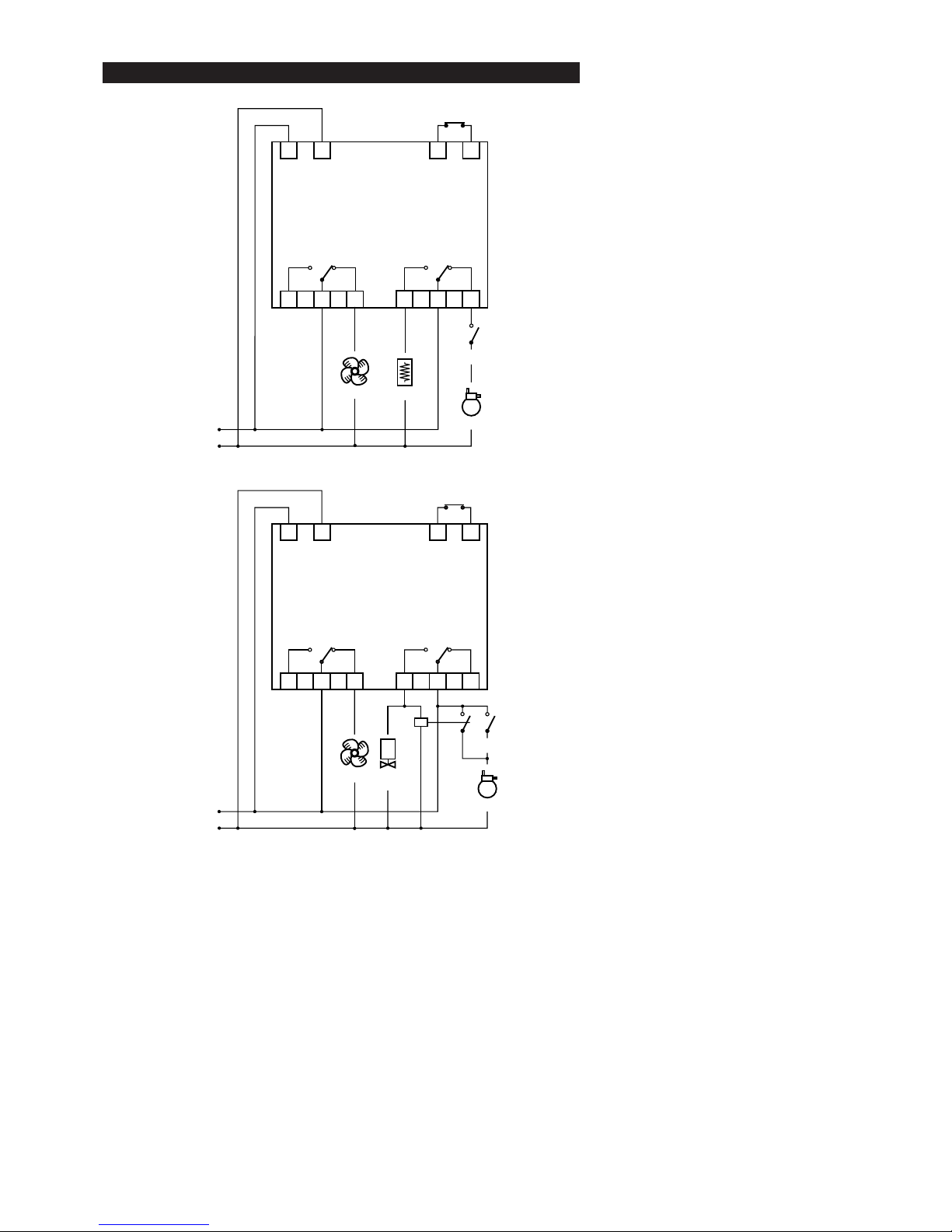
EWDR 72
(electric heater defrost)
10
1
3
13
15
17
12
Klixon
20
22
24
compressor
heaterfans
POWER SUPPLY
thermostat
EWDR 72
(hot gas defrost)
10
1
3
13
15
17
12
Klixon
20
22
24
compressor
hot gas
valve
fans
POWER SUPPLY
thermostat
CONNECTIONS
 Loading...