

Page 1
Ellisys USB Explorer 350
User Manual
Version 0.83
October 30, 2015
Page 2

Copyright, Confidentiality and Disclaimer Statements.
While the information in this publication is believed to be accurate, Ellisys makes no warranty of any kind to this
material including, but not limited to, the implied warranties of merchantability and fitness for a particular purpose .
Ellisys shall not be liable for any errors contained herein, or for incidental or consequential damages in connection
with the furnishing, performance or use of this material.
No part of this publication may be reproduced, stored in a retrieval system or transmitted, in any form or by any
User Guide
means, photocopying, recording or otherwise, without prior written consent of Ellisys. No third party intellectual
property right liability is assumed with respect to the use of the information contained herein. Ellisys assumes no
responsibility for errors or omissions contained in this book. This publication and features described herein are
subject to change without notice.
Copyright (C) Ellisys 2009. All rights reserved.
All products or services mentioned in this manual are covered by trademarks, service marks, or product names as
designated by the companies who market those products.
This manual is populated throughout with screens captured from a specific version of Ellisys Protocol Analyzer
software. All the information contained in the screens are samples and serve as instructional purposes only.
Document Revision History
Date Revision Changes
June 1, 2015 0.8 Initial release.
Ellisys Contact Details
Ellisys Phone: +41 22 777 77 89
Chemin du Grand-Puits 38 Fax: +41 22 777 77 90
CH-1217 Meyrin Geneva Email: [email protected]
Switzerland Web: www.ellisys.com
2 of 157
Page 3

Conditions of Use and
Limited Warranty Terms
These conditions and terms are deemed to be accepted by the customer at the t ime
the product is purchased, leased, lent or used, whether or not acknowledged in writing.
Conditions of Use
The customer is only authorized to use the product for its own activities, whether
professional or private. Thus, the customer is, in particular, forbidden to resell, lease or
lend the product t
right to disassembly, modify, copy, reverse engineer, create derivative works from or
otherwise reduce or alter the product. The product may also not be used in any
improper way.
Limited Warranty Coverage
Ellisys warrants to the original customer of its products that its products are free from
defects in material and workmanship for the warranty period. Subject to the conditions
and limitations set forth below, Ellisys will, at its option, either repair or replace any
part of its products that prove defective by reason of improper workmanship or
materials. Repaired parts or replacement products will be provided by Ellisys on an
exchange basis, and will be either new or refurbished to be functionally equivalent to
new. If Ellisys is unable to repair or replace the product, it will refund the current value
of the product at the time the warranty claim is made. In no event shall Ellisys' liability
exceed the original purchase price of product.
Excluded Products and Problems
This limited warranty does not cover any damage to this product that results from
improper installation, accident, abuse, misuse, natural disaster, insufficient or excessive
electrical supply, abnormal mechanical or environme
unauthorized disassembly, repair, or modification. This limited warranty also does not
apply to any product on which the original identification information has been altered,
obliterated or removed, has not been handled or packaged correctly, or has been sold
as second-hand. This limited warranty only applies to the original customer of the
product for so long as the original customer owns the product. This limited warranty is
non-transferable.
This limited warranty covers only repair, replacement or refund for defective Ellisys
products, as provided above. Ellisys is not liable for, and does not cover under
warranty, any loss of data or any costs associated with determining the source of
system problems or removing, servicing or installing Ellisys products.
Obtaining Warranty Service
To obtain warranty service, you may return a defective product to the authorized Ellisys
dealer or distributor from which you purchased the Ellisys product. Please confirm the
terms of your dealer's or di
Typically, you must include product identification information, including model number
and serial number with a detailed description of the problem you are experiencing. You
must also include proof of the date of original retail purchase as evidence that the
product is within the applicable warranty period.
The returned product will become the property of Ellisys. Repaired or replacement
product will be shipped at Ellisys' expense. Repaired or repl
continue to be covered by this limited warranty for the remainder of the original
warranty or 90 days, whichever is longer.
o any third party. In addition, the customer has, in particular, no
ntal conditions, or any
stributor's return policies prior to returning the product.
acement product will
ALL WARRANTIES NOT STATED HEREIN, INCLUDING, TO THE EXTENT PERMITTED BY
APPLICABLE LAW, ANY WARRANTY THAT MAY EXIST UNDER NATIONAL, STATE,
PROVINCIAL OR LOCAL LAW INCLUDING BUT NOT LIMITED TO ANY IMPLIED
WARRANTY OF NON-INFRINGEMENT, MERCHANTABILITY OR FITNESS FOR A
PARTICULAR PURPOSE. ALL WARRANTIES, WHETHER EXPRESS OR IMPLIED, ARE
LIMITED TO THE PERIODS OF TIME SET FORTH ABOVE. SOME STATES OR OTHER
JURISDICTIONS DO NOT ALLOW THE EXCLUSION OF IMPLIED WARRANTIES OR
LIMITATIONS ON HOW LONG AN IMPLIED WARRANTY LASTS, SO THE ABOVE
LIMITATIONS MAY NOT APPLY TO YOU.
ELLISYS PRODUCTS ARE NOT AUTHORIZED FOR USE AS CRITICAL COMPONENTS IN
LIFE SUPPORT EQUIPMENT OR FOR APPLICATIONS IN WHICH THE FAILURE OR
MALFUNCTION OF THE PRODUCTS WOULD CREATE A SITUATION IN WHICH
PERSONAL INJURY OR DEATH IS LIKELY TO OCCUR. ELLISYS SHALL NOT BE LIABLE
FOR THE DEATH OF ANY PERSON OR ANY LOSS, INJURY OR DAMAGE TO PERSONS
OR PROPERTY BY USE OF PRODUCTS USED IN APPLICATIONS INCLUDING, BUT NOT
LIMITED TO, MILITARY OR MILITARYEQUIPMENT, DISASTER PREVENTION SYSTEMS AND MEDICAL OR MEDICAL-RELATED
EQUIPMENT.
ELLISYS' TOTAL LIABILITY UNDER THIS OR ANY OTHER WARRANTY, EXPRESS OR
IMPLIED, IS LIMITE D T O RE P AI R, RE PL A C EM E NT OR RE F UND . RE PAI R , RE P L ACE ME N T
OR REFUND ARE THE SOLE AND EXCLUSIVE REMEDIES FOR BREACH OF WARRANTY
OR ANY OT
APPLICABLE LAW, ELLISYS SHALL NOT BE LIABLE TO THE CUSTOMER OF AN ELLISYS
PRODUCT FOR ANY DAMAGES, EXPENSES, LOST DATA, LOST REVENUES, LOST
SAVINGS, LOST PROFITS, OR ANY OTHER INCIDENTAL OR CONSEQUENTIAL
DAMAGES ARISING FROM THE PURCHASE, USE OR INABILITY TO USE THE ELLISYS
PRODUCT, EVEN IF ELLISYS HAS BEEN ADVISED OF THE POSSIBILITY OF SUCH
DAMAGES. SOME STATES OR OTHER JURISDICTIONS DO NOT ALLOW THE
EXCLUSION OR LIMITATION OF INCIDENTAL OR CONSEQUENTIAL DAMAGES, SO THE
ABOVE LIMITATIONS OR EXCLUSIONS MAY NOT APPLY TO YOU.
Severability
If any provision or any portion of any provision contained in these terms is held to be
invalid, illegal or unenforceable by a court of competent jurisdiction, then the remaining
provisions, and if a portion of any provision is unenforceable, then the remaining
portion of such provision shall, nevertheless, remain in full force and effect. The parties
undertake to negotiate in good faith with a view to replace such invalid,
unenforceable provision or part thereof with another provision not so invalid, illegal or
unenforceable with the same or similar effect, and further agree to be bound by the
mutually agreed substitute provision.
Warranty Period
The warranty begins on the date of purchase and covers a period of two (2) years.
Governing Law
These conditions and terms shall be governed by and construed in accordance with the
law of Switzerland.
Jurisdiction; Venue
The parties consent to the exclusive personal jurisdiction of, and venue in, the District
Court of Geneva, Switzerland.
HER LEGAL THEORY. TO THE FULLEST EXTENT PERMITTED BY
RELATED EQUIPMENT, TRAFFIC CONTROL
illegal or
Ellisys USB Explorer 350
Limitations
THE FOREGOING IS THE COMPLETE WARRANTY FOR ELLISYS PRODUCTS AND
SUPERSEDES ALL OTHER WARRANTIES AND REPRESENTATIONS, WHETHER ORAL OR
WRITTEN. EXCEPT AS EXPRESSLY SET FORTH ABOVE, NO OTHER WARRANTIES ARE
MADE WITH RESPECT TO ELLISYS PRODUCTS AND ELLISYS E XPRESSLY DISCLAIMS
3 of 157
Page 4

Table of Contents
1. Analyzer / Exerciser Overview ........................................................... 10
2. Installing the Applications ................................................................. 15
3. Connections and Indicators ............................................................... 17
4. Analyzer User Interface Reference .................................................... 25
5. Exerciser User Interface..................................................................... 31
6. Examiner User Interface .................................................................... 57
7. Analyzer Trace File Management ...................................................... 63
1
1.1 Introduction.......................................................................................................................10
1.2 Major Features and Capabilities...........................................................................................11
User Guide
1.3 Analyzer Description...........................................................................................................12
1.4 Exerciser Description ..........................................................................................................13
1.5 Examiner Compliance Test Suite Decription.......................................................................... 13
2.1 Software and Hardware Prerequisites.................................................................................. 15
2.2 Software Installation ..........................................................................................................16
3.1 Standard-A and Standard-B Receptacles.............................................................................. 17
3.2 LED Indicators on Unit and Adapter..................................................................................... 17
3.3 Logic Connector .................................................................................................................21
3.4 DC Power and USB Control Connection................................................................................ 23
3.5 Inter-Unit Sync Connections................................................................................................23
3.6 Connecting to the Control Computer....................................................................................24
4.1 Organizing Panes ............................................................................................................... 26
4.2 Main Toolbar...................................................................................................................... 27
4.3 Main Menu.........................................................................................................................28
5.1 Power Delivery Settings and Controls .................................................................................. 34
5.2 USB 3.x LFPS Settings and Controls.....................................................................................50
5.3 USB 3.x Data Pump Settings and Controls............................................................................ 54
7.1 Opening a Trace File .......................................................................................................... 63
7.2 Saving a Trace File.............................................................................................................63
7.3 Opening a Sample Trace File............................................................................................... 64
4 of 157
Page 5

7.4 Printing a Trace File............................................................................................................64
8. Analyzer Workspaces and Layouts .................................................... 69
9. Analyzer – Setting Up ........................................................................ 79
10. Managing Analyzer Recordings ......................................................... 84
11. Analyzer Overview Windows ............................................................. 92
12. Analyzer Instant Timing Pane .......................................................... 112
7.5 Importing Data to View in a Trace File................................................................................. 66
7.6 Exporting a Trace File.........................................................................................................67
8
8.1 Using Workspaces.............................................................................................................. 69
8.2 Using Layouts .................................................................................................................... 77
9.1 Analyzer Hardware Setup – Type-C ..................................................................................... 79
9.2 Analyzer Hardware Setup – USB Standard Cables.................................................................80
9.3 Analyzer Hardware Setup – Alternate Setup for CC Capture .................................................. 81
9.4 Analyzer Hardware Setup – Devices with Captive Cable ........................................................ 82
9.5 Analyzer Hardware Setup – Passive Tapping to Board........................................................... 83
10.1 Setting the Recording Options.............................................................................................84
10.2 Selecting an Analyzer ......................................................................................................... 90
10.3 Initiating a Recording ......................................................................................................... 91
10.4 Stopping a Recording ......................................................................................................... 91
10.5 Restarting a Recording ....................................................................................................... 91
Ellisys USB Explorer 350
11.1 Configuring the Display....................................................................................................... 92
11.2 Applying Display Filters.......................................................................................................98
11.3 Grouping and Ungrouping................................................................................................. 101
11.4 Timing Measurements ...................................................................................................... 102
11.5 Tracking Link State Changes............................................................................................. 103
11.6 Synchronization to Other Panes......................................................................................... 103
11.7 Using Markers.................................................................................................................. 104
11.8 Search Features ............................................................................................................... 106
12.1 Panning Left and Right ..................................................................................................... 113
12.2 Zooming In and Out......................................................................................................... 114
12.3 Setting a Symbol Format................................................................................................... 117
12.4 Taking Measurements....................................................................................................... 117
12.5 Exporting Images............................................................................................................. 119
5 of 157
Page 6

12.6 Link State Indications ....................................................................................................... 119
13. Analyzer Summary Pane .................................................................. 125
14. Analyzer Instant Link State Pane ..................................................... 127
15. Analyzer Details Pane ...................................................................... 130
16. Analyzer Raw Data Pane .................................................................. 133
17. Analyzer Protocol Error Verifications .............................................. 135
18. Analyzer Task Pane .......................................................................... 139
19. Analyzer Recording Activity Menu ................................................... 140
20. Exerciser or Examiner – Setting Up ................................................. 147
21. Updating the Application Software ................................................. 150
12.7 Synchronizing to Other Views............................................................................................ 120
1
User Guide
19.1 General............................................................................................................................ 141
19.2 Performance .................................................................................................................... 142
19.3 Advanced......................................................................................................................... 144
19.4 Options............................................................................................................................ 145
20.1 Generator (or Examiner) and Analyzer Setup ..................................................................... 147
20.2 Generator (or Examiner) Setup without Analyzer................................................................ 147
20.3 Generator (or Examiner) Setup for E-Marked Cable ............................................................ 148
21.1 Analyzer Updates ............................................................................................................. 155
21.2 Examiner and Generator Updates...................................................................................... 155
6 of 157
Page 7

Table of Figures
Figure 1 Ellisys USB Explorer 350 Analyzer/Exerciser/Compliance Tester..................................................... 11
Figure 2 Simplified Setup for Analyzer Mode ............................................................................................13
Figure 3 Simplified Exerciser or Examiner Setup (Host Emulation Example).................................................14
Figure 4 Simplified Exerciser or Examiner Setup (Device Emulation Example)............................................ 14
Figure 5 USB Explorer 350 Standard-A and Standard-B Receptacles .......................................................... 17
Figure 6 LED Locations ............................................................................................................................ 18
Figure 7 Type-C Adapter.......................................................................................................................... 21
Figure 8 Pin Layout for Logic Connector.................................................................................................... 22
Figure 9 Fying Leads Probe.....................................................................................................................23
Figure 10 View of Connector on Flying Leads Probe.................................................................................. 23
Figure 11 USB Explorer 350 Exerciser Interface......................................................................................... 31
Figure 12 USB Power Delivery General Tab............................................................................................... 34
Figure 13 Source Capabilities Interface.....................................................................................................36
Ellisys USB Explorer 350
Figure 14 Sink Capabilities Interface.........................................................................................................38
Figure 15 Edit VDM Identity..................................................................................................................... 40
Figure 16 Edit VDM Modes.......................................................................................................................41
Figure 17 USB Power Delivery Commands Tab.......................................................................................... 42
Figure 18 USB Power Delivery Checks Tab................................................................................................ 43
Figure 19 USB Power Delivery BIST Tab ................................................................................................... 45
Figure 20 Exerciser Advanced Tab............................................................................................................47
Figure 21 Exerciser Settings Tab .............................................................................................................. 49
Figure 22 USB 3.x LFPS Settings and Controls..........................................................................................50
Figure 23 USB 3.x LFPS Advanced Tab .................................................................................................... 52
Figure 24 USB 3.x Settings Tab...............................................................................................................53
Figure 25 USB 3.x Data Pump General Tab .............................................................................................. 54
Figure 26 USB 3.x Data Pump Advanced Tab ...........................................................................................55
Analyzer / Exerciser Overview | 7 of 157
Page 8

Figure 27 USB 3.x Data Pump Settings Tab.............................................................................................. 56
Figure 28 Examiner User Interface (Tests Tab Shown) ............................................................................. 57
Figure 29 Examiner Results Tab.............................................................................................................. 59
Figure 30 Sample Summary Report ......................................................................................................... 60
Figure 31 Examiner Settings Tab.............................................................................................................61
User Guide
Figure 32 Settings Tab............................................................................................................................62
Figure 33 Basic Analyzer Setup ...............................................................................................................79
Figure 34 Basic Analyzer Setup Using Standard USB Cables ....................................................................... 80
Figure 35 Alternate Analyzer Setup for CC Capture.................................................................................... 81
Figure 36 Analyzer Setup for Captive Cable..................................................................................... ..........82
Figure 37 Analyzer Setup to Tap Board Directly......................................................................................... 83
Figure 38 Recording Options Menu...........................................................................................................84
Figure 40 Analyzer and Generator (or Examiner) Setup............................................................................ 147
Figure 41 Generator (or Examiner) Setup without Analyzer...................................................................... 148
Figure 42 Generator (or Examiner) Setup for E-Marked Cable ................................................................. 149
8 of 157
Page 9
About this Manual
A
A
A
Typographic Conventions
Bold is used to indicate menu commands, buttons, and tabs.
Italics
are used to indicate fields, pane names, window names and cross references.
warning symbol describes a possible critical situation and how to avoid it.
n information symbol tells you how to respond to a situation that may arise.
tip symbol tells you information that will help you carry out a procedure.
Where to Find More Help
Ellisys USB Explorer 350
Go to the Ellisys website and the following pages for the latest information:
Ellisys products page - Go to www.ellisys.com/products/ for the latest product information and
documentation.
Application notes and white papers - Go to www.ellisys.com/technology/ to find up-to-date
information about the technology.
Distributors - Go to ww w.ellisys.com/sales/ to find a list of Ellisys distributors.
Technical support - Go to www.ellisys.com/support/ to send a question directly to the Ellisys
support team.
Analyzer / Exerciser Overview | 9 of 157
Page 10

1. Analyzer / Exerciser Overview
1.1 Introduction
The Ellisys USB Explorer™ 350 Analyzer/Exerciser is an advanced test and analysis system for various USB
technologies, including:
User Guide
DisplayPort Support
The USB Explorer 350 also provides support for DisplayPort Alternate Mode operation. The Analyzer decodes
DisplayPort commands over USB Power Delivery protocol. The Exerciser supports sending these commands and
responding to them. The Examiner™ compliance test suite provides various tests for DisplayPort Alternate Mode
operation.
Support for other Alternate Modes may be added – please check with Ellisys for details at [email protected]
Configurability
The USB Explorer 350 may be configured at purchase or feature-upgraded thereafter to add various protocol analysis
features, traffic generation, and compliance testing capabilities.
x USB Power Delivery
x USB Type-C Connectors and Electronically Marked Cables
x SuperSpeed USB 3.1 (Gen1 and Gen2)
x USB 2.0
x Alternate Mode Support
.
Software Applications Available
Three associated software applications determine the mode in which the USB Explorer 350 will operate. These
include the Analyzer application, the Exerciser application, and the Examiner compliance test suite application.
Download information for these software applications can be requested at www.ellisys.com/support/download.php
10 of 157 | Analyzer / Exerciser Overview
.
Page 11
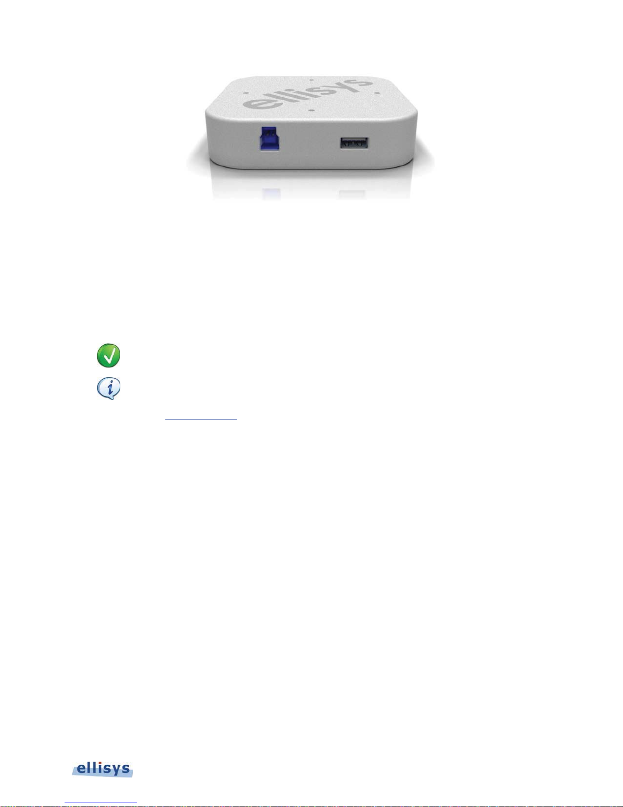
Figure 1 Ellisys USB Explorer 350 Analyzer/Exerciser/Compliance Tester
T
1.2 Major Features and Capabilities
The USB Explorer 350 is designed to provide the major features and capabilities listed below.
o see a list of features enabled on your USB Explorer 350, please check the Help menu with the
unit connected to your PC over USB.
Certain features may be option purchases. Most options can be enabled by means of an
electronic enable provided by Ellisys. Certain features may be in early development stages.
Contact [email protected] for details.
Ellisys USB Explorer 350
Analyzer / Exerciser Overview | 11 of 157
Page 12

Analysis and Emulation
USB 3.1 (Gen1 and Gen2) hosts and devices
USB Power Delivery UFPs, DFPs, and DRPs
USB Type-C Electronically Marked cables
USB PD Alternate Modes
User Guide
USB 2.0 hosts, devices, and hubs (analysis only)
Compliance Testing
USB 3.1 hosts, devices, and hubs
USB Power Delivery providers, consumers, and DRPs
Type-C Electronically Marked cables
1.3 Analyzer Description
In Analyzer mode, the USB Explorer 350 records USB 2.0, USB Power Delivery traffic and events, supported Alternate
Mode traffic (such as DisplayPort) and/or USB 3.1 (Gen1 and Gen2) traffic and bus events occurring between two
USB system components, such as a host and device or a provider and consumer, and presents comprehensive
analytical information to the user, including detailed packet, transaction, and transfer level information, statistical and
performance metrics, logic signals capture, protocol error detection, link state analysis, timing characterizations, and
other related information.
During recording, captured traffic and other bus events are uploaded over a USB 3.1 Gen 1 connection to the control
computer for display in real time. The Analyzer software application provides various controls to manage how
information is displayed, filtered, and captured.
12 of 157 | Analyzer / Exerciser Overview
Page 13
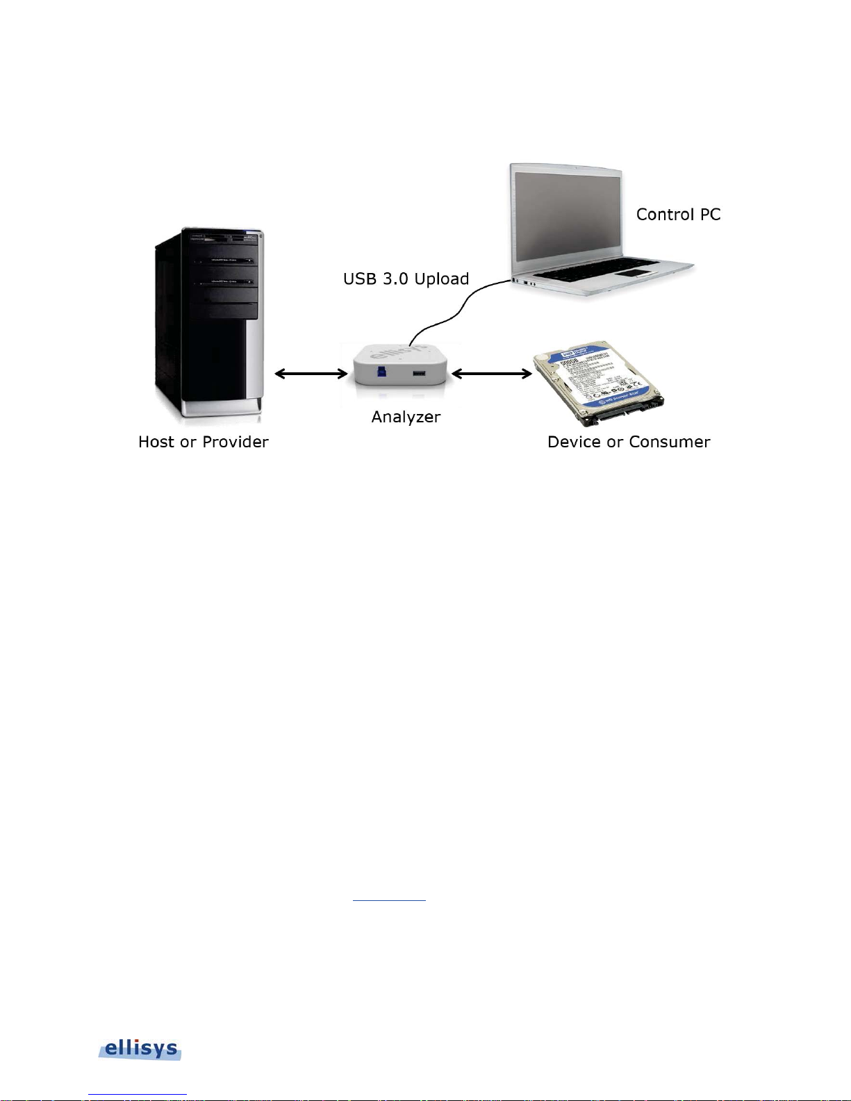
Figure 2 below depicts a
Explorer 350 is required, but not shown.
simplified
setup for Analyzer mode. Note that the supplied 24VDC power input for the USB
Figure 2 Simplified Setup for Analyzer Mode
Ellisys USB Explorer 350
1.4 Exerciser Description
In Exerciser mode, the USB Explorer 350 emulates a USB or USB Power Delivery port or device for purposes of
characterizing another port or device, or the physical media. In this mode, the USB Explorer 350 essentially replaces
a system component. For example, it may be configured to emulate a USB host and then be connected to a USB
device, or it may emulate a USB Power Delivery consumer in order to test the corresponding provider or a Type-C
Electronically Marked cable plug.
In this mode, two USB Explorer 350 units are typically used: one to act as the Exerciser, and the other to act as
Analyzer, capturing traffic between the Exerciser and the device under test (DUT) for debug and characterization
purposes.
1.5 Examiner Compliance Test Suite Description
The USB Explorer 350 uses the Examiner application to execute compliance or verification tests against a USB host,
device, USB PD Downstream-Facing Port (DFP) Upstream-Facing Port (UFP), Dual-Role Port (DRP), Type-C
electronically marked cable, hub, etc.
Examiner’s tests are based on USB-IF compliance testing documents. Pass/fail criteria as well as test methodologies
are covered in these documents. Please visit www.usb.org
In Examiner mode, two USB Explorer 350 units are typically used; one to act as the Examiner unit and the other t o
act as Analyzer, capturing per-test traffic between the Examiner and the device under test (DUT) for debug
purposes. A single Examiner unit however can be used to execute all tests, but in this mode, traces are not
captured.
for details.
Analyzer / Exerciser Overview | 13 of 157
Page 14
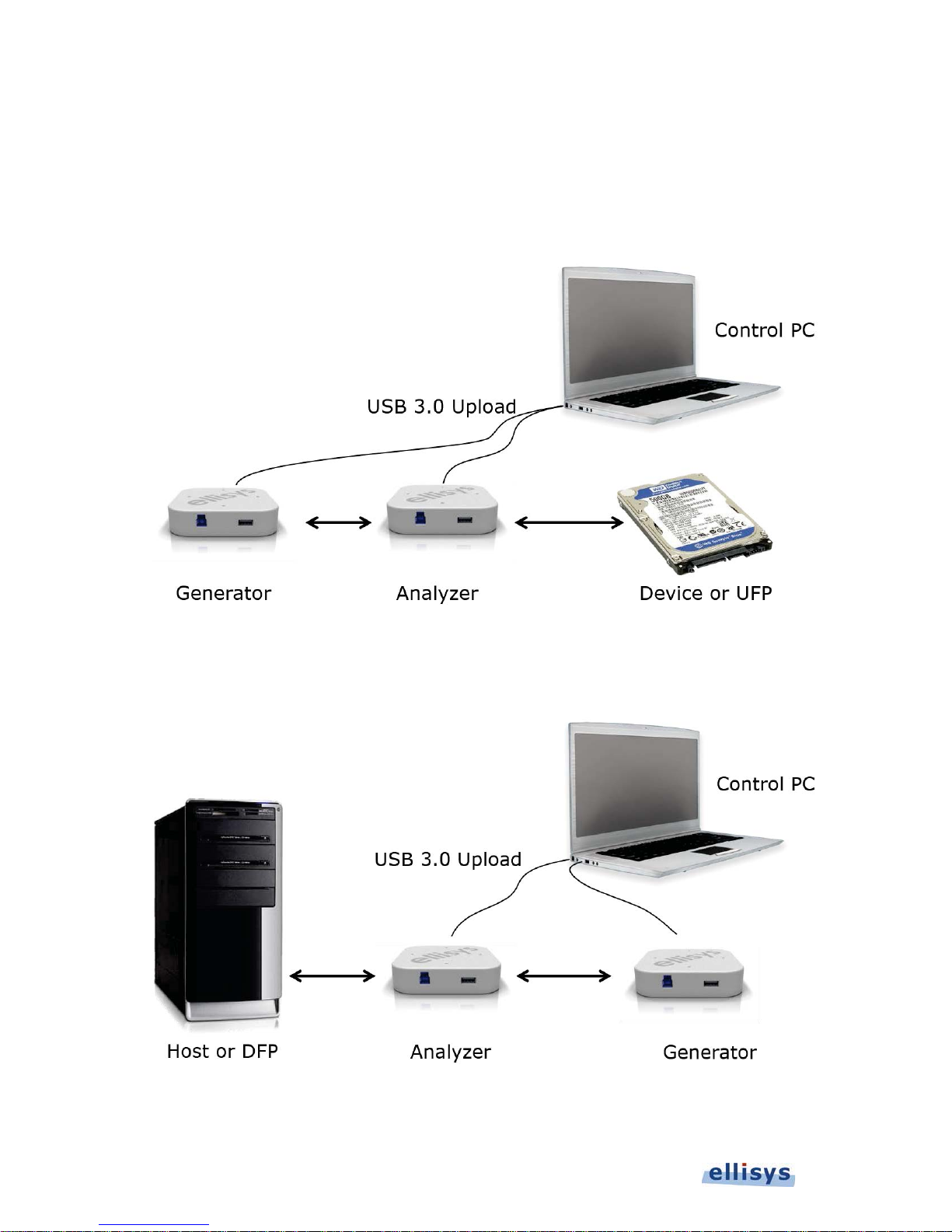
In the two-unit setup, the Analyzer may be operated automatically under the control of the Examiner application to
capture traces for each test, or it may be operated by the user manually, under the control of the Analyzer
application directly (when the Analyzer checkbox in Examiner’s Settings tab is unchecked).
Figure 3 and Figure 4 below depict a
input for the USB Explorer 350 units are required, but not shown.
simplified
setup for Exerciser mode or Examiner. Note that the 24VDC power
User Guide
Figure 3 Simplified Exerciser or Examiner Setup (Host Emulation Example)
Figure 4 Simplified Exerciser or Examiner Setup (Device Emulation Example)
14 of 157 | Analyzer / Exerciser Overview
Page 15

2. Installing the Applications
2.1 Software and Hardware Prerequisites
Before installing the USB Explorer 350 Analyzer, Exerciser, or Examiner applications, please ensure the computer
system on which these will reside meet the following requirements:
Microsoft Windows XP SP1 or later.
Microsoft Windows Installer 3.0 or later. If the installation does not run smoothly, or if the system
indicates a version error, update your Windows installer.
Microsoft .NET Framework version 4.0 or later.
Intel Core, 1.5 GHz or compatible processor, or better.
512 MB RAM or more.
1280 x 1024 screen display resolution with 65,536 colors, or better.
USB 2.0 Host Controller (USB 3.1 Gen1 recommended).
The USB Explorer 350 applications require several software components. Ellisys recommends that you visit the
following web pages as needed to update your versions of Microsoft .NET Framework and Windows:
www.microsoft.com/net
www.update.microsoft.com to update your version of Windows. When using the Windows update
service it will automatically download and install the Microsoft .NET Framework version 4.0.
See your system administrator for more information about updating Microsoft .NET Framework and Windows.
to download the Microsoft .NET Framework version 4.0.
Ellisys USB Explorer 350
Installing the Applications | 15 of 157
Page 16
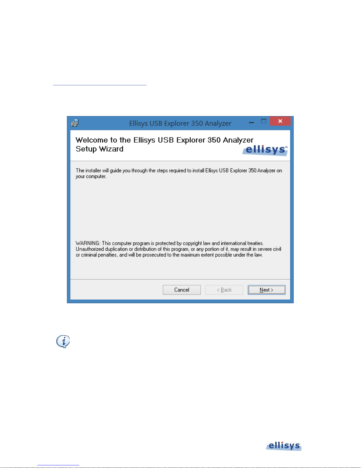
2.2 Software Installation
A
1. Insert the CD-ROM or other media that accompanies the product into the computer’s CD-ROM drive. You may
also download the applications and run the installation from these downloads. Visit
www.ellisys.com/support/download.php
to request application software.
The Ellisys USB Explorer 350
Examiner applications will vary accordingly).
User Guide
Setup Wizard
screen appears (Analyzer installation is shown below; Exerciser and
2. Follow the dialog prompts to install the software application. Note that detailed installation instructions are not
provided here, but are explained in the installation dialogs.
fter installing any of the USB Explorer 350 software applications, a New Hardware Wizard may
appear if your USB Explorer 350 unit is connected to a PC. Refer to section 3.6, Connecting to
the Control Computer, for more information about installing the USB driver.
16 of 157 | Installing the Applications
Page 17
3. Connections and Indicators
The USB Explorer 350 includes various receptacles on all four sides, and a set of four multi-color LEDs on the top
that provide various capture, generate, input power, and control connection indications.
For Type-C applications, an externalized Type-C connection is provided through use of a supplied custom “Y” cable
and associated adapters.
3.1 Standard-A and Standard-B Receptacles
Ellisys USB Explorer 350
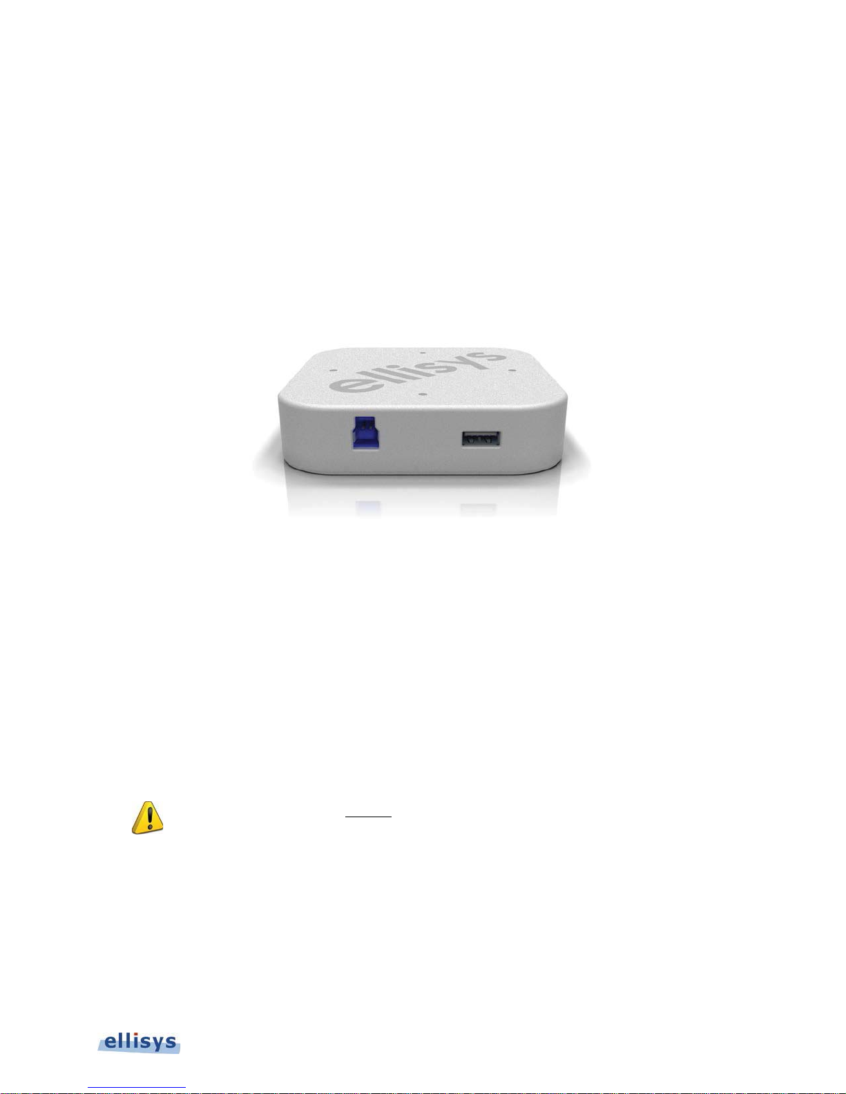
Figure 5 USB Explorer 350 Standard-A and Standard-B Receptacles
Upstream (Standard-B) Receptacle
The Upstream connector is usually used to connect the USB Explorer 350 to a host or a downstream-facing port on a
hub (for USB 2.0 or 3.1 applications). For USB Type-C applications, this receptacle is connected to the supplied
custom “Y” cable.
Downstream (Standard-A) Receptacle
The Downstream connector is usually used to connect the USB Explorer 350 to a device or an upstream-facing port
on a hub (for USB 2.0 or 3.1 applications). For USB Type-C applications, this receptacle is connected to the supplied
custom “Y” cable.
When connecting USB cables DO NOT force the connector into the unit. The metal part of the
connector should not be inserted completely into the connection port. Forcing the connector or
inserting all of the metal part of the connector can break the port connection and is not covered
by the warranty.
3.2 LED Indicators on Unit and Adapter
The USB Explorer 350 provides four multi-color LEDs on the top of the unit for various statuses and indications
regarding input power, the USB control connection, multi-unit synchronization, and traffic being captured or
generated.
Connections and Indicators | 17 of 157
Page 18
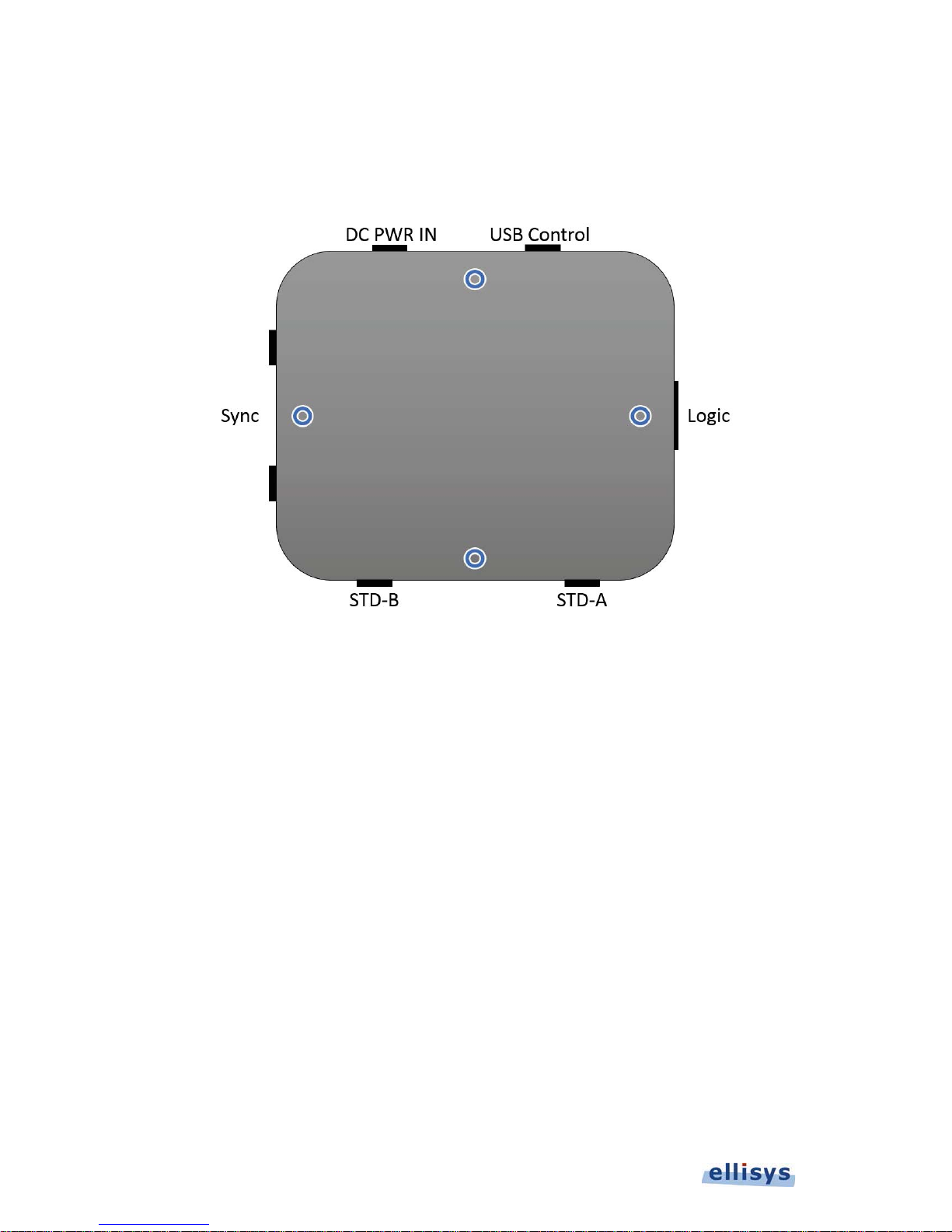
In addition, the Type-C Adapter includes two LEDs that provide various indications specific to port connection
statuses.
LEDs on the USB Explorer 350
User Guide
Figure 6 LED Locations
18 of 157 | Connections and Indicators
Page 19
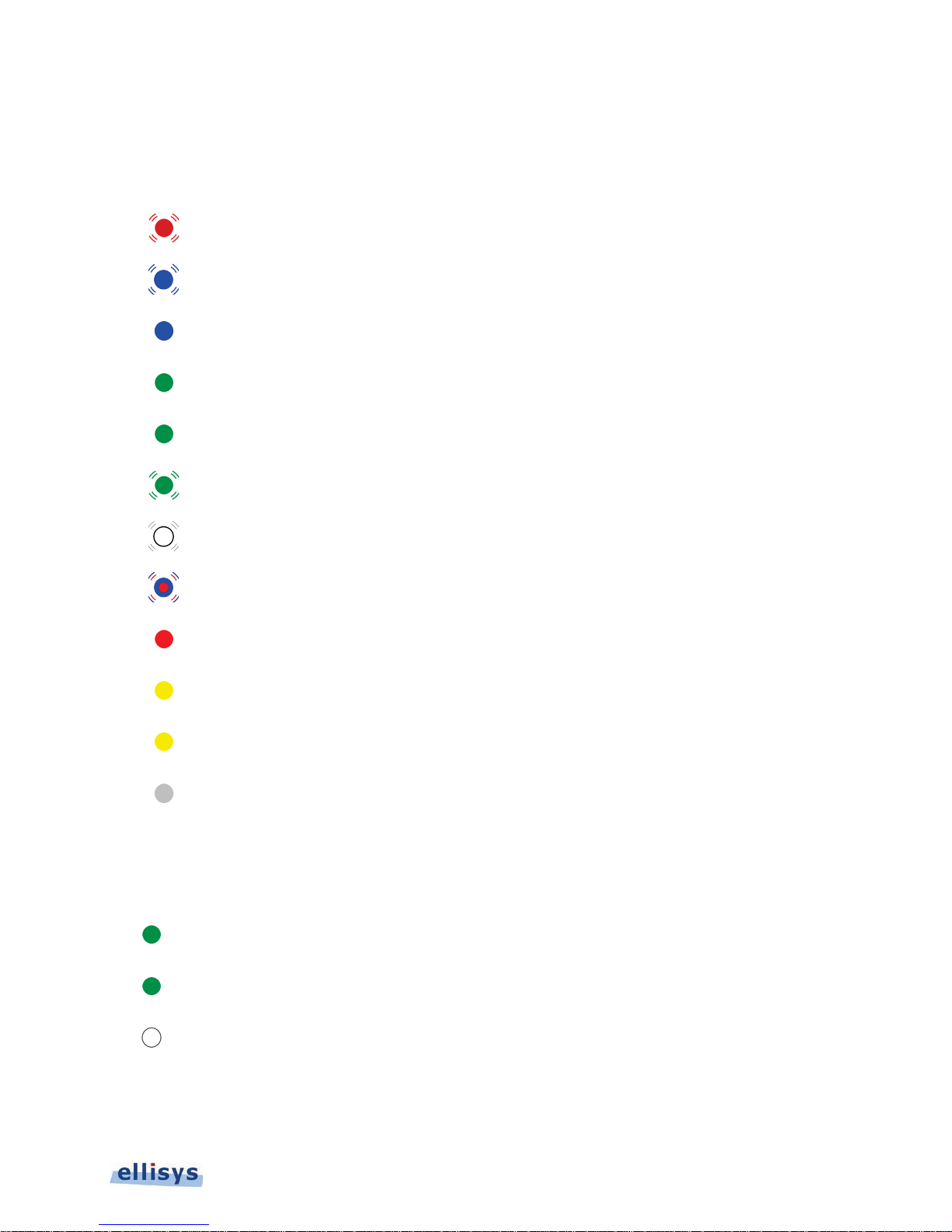
DC PWR IN/USB Control LED
Y
Y
The DC PWR IN/USB Control LED provides various statuses on the DC power input, USB control connection,
operating status, and application-initiated unit identifications.
Red blinking: DC Power connected. USB control not connected.
Blue blinking: USB control connected - driver not loaded.
Blue steady: USB control connected - driver loaded.
Green steady (Analyzer): Powered, connected and capturing.
Green steady (Exerciser): Powered, connected, and operating.
Green blinking: Powered but not connected.
White blinking: Driven by software applications when serial number is selected.
Ellisys USB Explorer 350
Red/blue blinking: Power failure.
Red steady: Application active – memory full.
ellow steady (Analyzer): Application active but not capturing.
ellow steady (Exerciser): Processor is paused (in a breakpoint).
Off: Not powered and not connected. The PWR LED may also be off if when the unit is in power-
saving mode after the control computer has been turned off.
Logic LED
The Logic LED indicates various input/output statuses.
Green (Analyzer): Illuminated when any transition is detected on enabled signals.
Green (Exerciser): Illuminated when state of any enabled output changes.
White: Trigger OUT generated.
Connections and Indicators | 19 of 157
Page 20

USB STD-A/STD-B LED
Y
Y
V
V
The STD-A/STD-B LED provides various statuses on traffic types, error detection, and termination detection.
Green steady: In USB 2.0 mode.
User Guide
ellow steady: USB 3.x terminations detected on both ports.
ellow blinking: USB 3.x terminations detected on one port only.
Blue steady: In USB 3.1 Gen 1 mode.
Cyan steady: In USB 3.1 Gen 2 mode.
White blinking (Analyzer): Trigger detected.
iolet blinking (Analyzer): USB PD data detected.
iolet blinking (Exerciser): Transmitting USB PD packet.
Red blinking (Analyzer): Traffic error detected.
Sync LED
The Sync LED provides master/slave indications when multiple units are synchronized.
Green: Synchronized as slave unit.
White: Synchronized as master unit.
LEDs on the Type-C Adapter
There are two LEDs on the Type-C adapter, one associated with the From UFP label, and one associated with the
From DFP label. LED colors (off, orange, or green) are based on the voltage of the CC line as described below.
20 of 157 | Connections and Indicators
Page 21
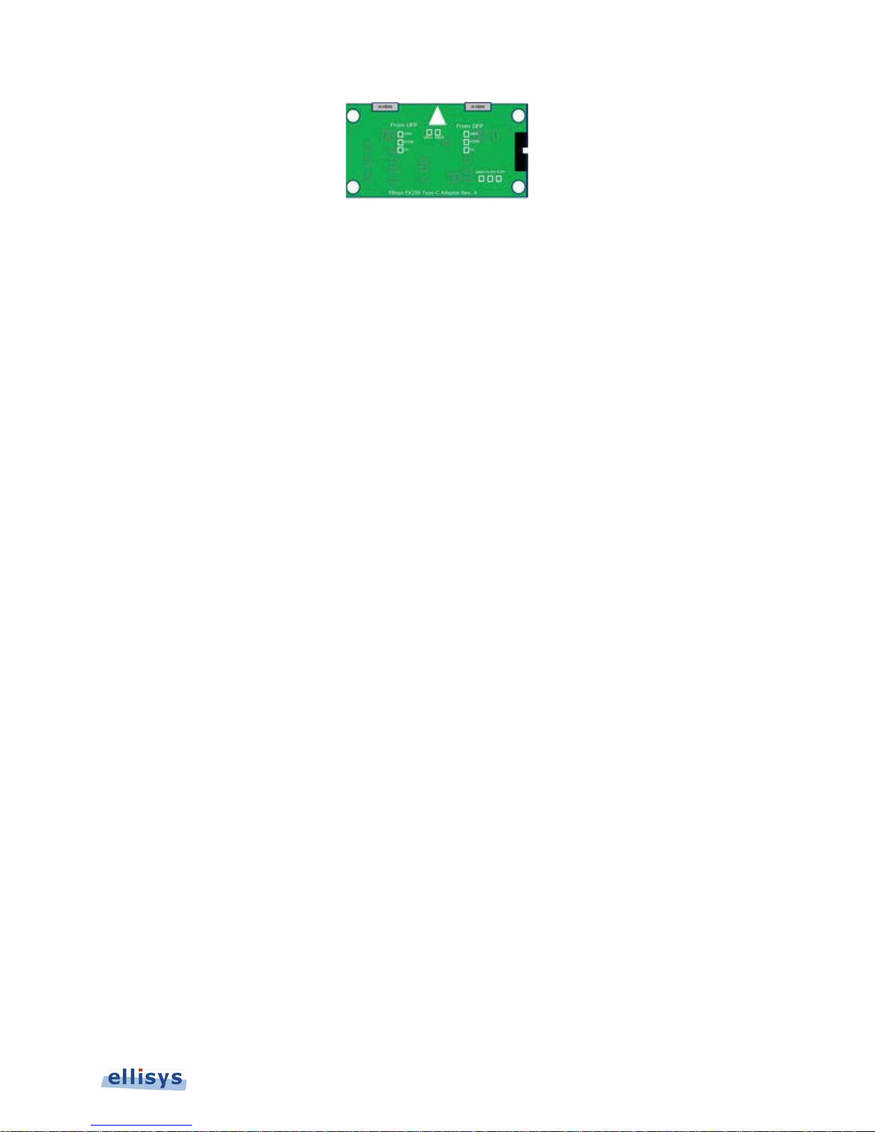
Figure 7 Type-C Adapter
Off Near zero voltage on CC. The CC line is floating when neither UFP nor DFP are
attached. When only the UFP is attached, the LED remains off as this attachment
provides a pull-down that is not recognized by the adapter circuitry.
Orange 5V (or near 5V), indicating the DFP alone is attached.
Green Indicates a valid connection voltage (cRd-Connect, 0.25V..2.04V).
3.3 Logic Connector
The logic connector exposes 20 pins (2 rows of 10 pins each) spaced at 1.27mm x 1.27mm. A ground is provided
along with 16 input/output pins. There are two unused pins. This connector may also be used for adapting to TypeC or USB Power Delivery implementations using the supplied Type-C adapter and associated flat cable.
CC Line Logic Capture
Ellisys USB Explorer 350
Pin 15 is dedicated for logic capture of the CC line (this can be enabled in the
flat cable is used, all other logic inputs are precluded from use.
Recording Options
menu). When the
Connections and Indicators | 21 of 157
Page 22
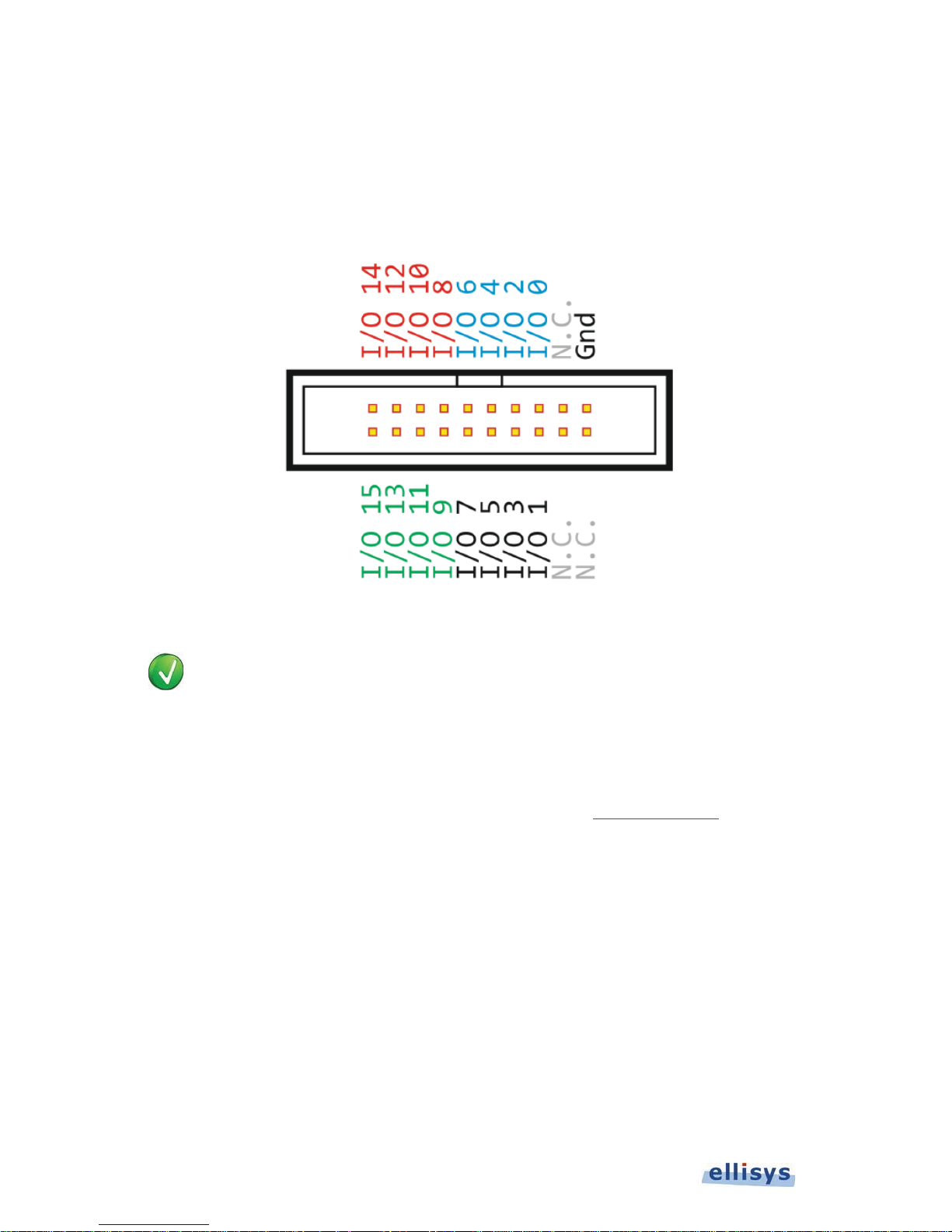
GPIO Placement on Logic Connector
The general-purpose inputs and outputs (GPIOs) can be used for logic signal capture (up to 16 signals) and to
control the capture process (start, stop, or pause the capture). Enabling logic signals capture or other Logic
Connector inputs is explained in Figure 8 below illustrates the layout of the pins on the USB Explorer 350 Logic
Connector.
User Guide
Figure 8 Pin Layout for Logic Connector
In some cases, USB Power Delivery signaling (CC) and related GND may be applied directly to
this connector for Analyzer capture (without use of the custom cable or adapters). GND and I/O
15 are reserved for this purpose.
In these cases, control of resistors Rp and Rd are left to the control of the user and are not
controlled by the USB Explorer 350 or the associated Type-C adapter. To prevent a false detect
by the device attached, the user may need to install a series resistor on the CC input ranging
between 9K Ohms and 20K Ohms. Contact Ellisys for support ([email protected]).
Flying Leads Probe
A Flying Leads probe is provided to connect to the Logic Connector. Captured logic signals are displayed in the
Instant Timing
that attaches to the Logic Connector on the side of the USB Explorer 350, with loose wires (female sockets) wires on
the other end.
view and are captured concurrently with other types of traffic. This probe includes a polarized plug
22 of 157 | Connections and Indicators
Page 23
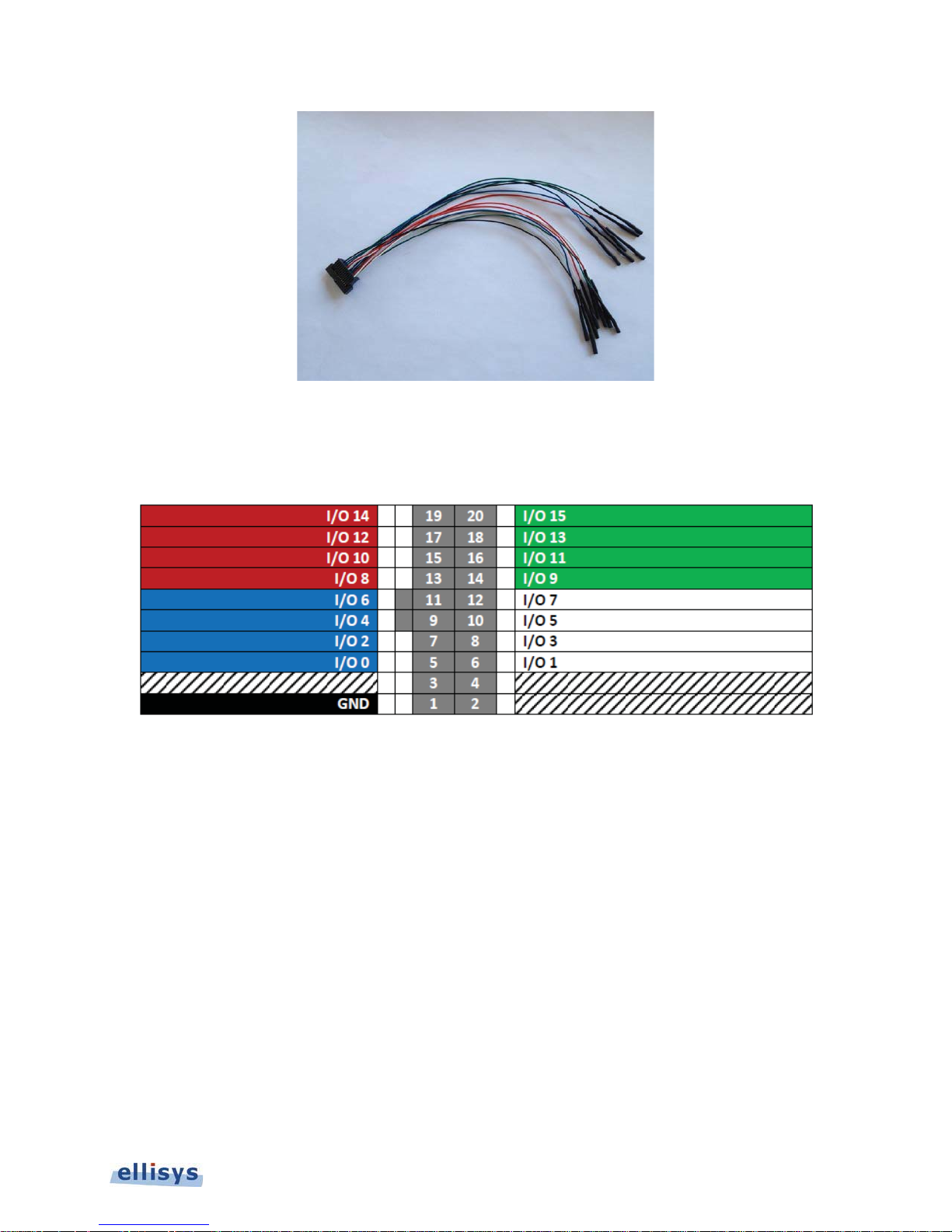
Figure 9 Flying Leads Probe
Figure 10 below illustrates the polarized female plug on the probe as well as wire colors (view is facing the end of the
plug).
Figure 10 View of Connector on Flying Leads Probe
3.4 DC Power and USB Control Connection
The USB Explorer 350 provides a DC Input Jack for supplying unit operating voltage and Vbus power. A USB 3.1
(Gen 1) port is provided for connection to a control PC.
Ellisys USB Explorer 350
An external 24VDC power supply is supplied with the system. The unit requires a minimum power of 18W.
The USB control connection is used by the connected Ellisys application to control the USB Explorer 350 and upload
captured data when in Analyzer mode. Captured data is streamed to the hard drive on the Control Computer.
3.5 Inter-Unit Sync Connections
The USB Explorer 350 provides two Micro A/B USB receptacles that are used to time-synchronize multiple units. This
approach allows for multiple captures from different units to be displayed in a single Analyzer application, with a
common time base.
Connections and Indicators | 23 of 157
Page 24

Note: Check with Ellisys for confirmation that this feature is enabled.
3.6 Connecting to the Control Computer
A PC hosting the Analyzer, Exerciser, and/or Examiner applications, enabling the use of any notebook or desktop
computer, controls the USB Explorer 350 over a USB 3.1 (Gen 1) connection. The USB driver must be installed
before the USB Explorer 350 can be used.
User Guide
Ellisys strongly recommends that you connect the Explorer 350 to a SuperSpeed USB (USB
3.0/USB 3.1) port on the Control Computer to obtain optimal performance.
Installing the USB Driver:
The precise installation procedure for the USB driver will vary according to the operating system being used. In most
cases, the OS should automatically install the driver when the Analyzer is attached to the Control Computer, possibly
with some prompts required from the user.
If necessary, the user may be able to install the driver from Device Manager, by pointing to the USB Driver, which is
located in the
Drivers
folder of the Ellisys installation directory. For example:
C:\Program Files (x86)\Ellisys\Ellisys USB Explorer 350 Analyzer\Drivers
24 of 157 | Connections and Indicators
Page 25
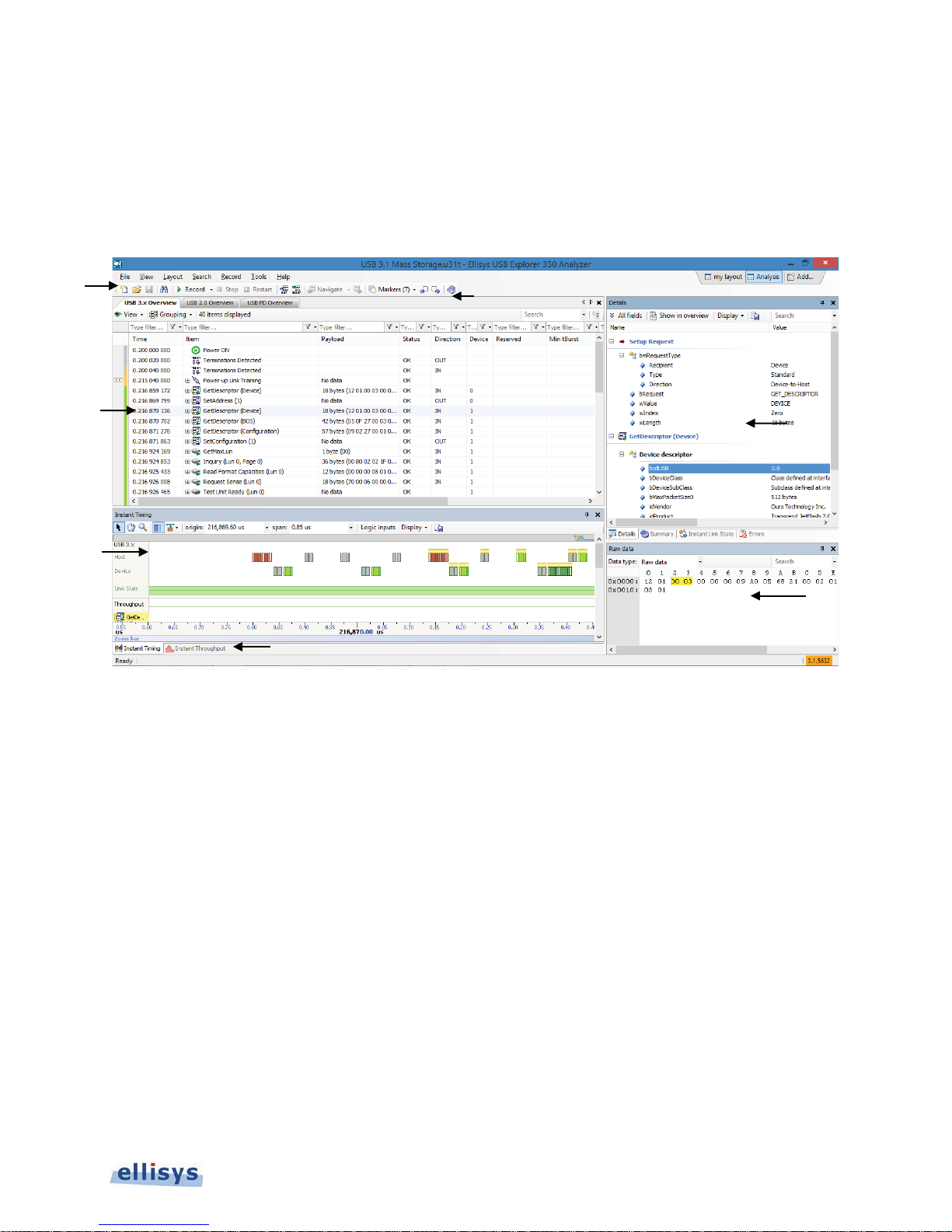
4. Analyzer User Interface Reference
USB 3.x Overview
USB 2.0 Overview
USB PD Overview
Details Pane
Raw Data Pane
Instant Timing Pane
Summary Pane
Instant Link State Pane
r
T
The user interface of the USB Explorer 350 Analyzer application provides various windows, panes, menus, toolbars,
and other visual elements. All panes are dockable, can be hidden or resized, and most are inter-linked to provide
synchronization with other panes.
Menu Ba
Overview
Instant Timing
Pane
oolbar
Details Pane
(other panes
docked)
Ellisys USB Explorer 350
Raw Data Pane
Instant Throughput Pane
The Analyzer application displays several windows and panes in the default layout. Each pane displays specific
information or allows the user to interact with the software for a given task:
U
Gen1 and Gen 2 traffic.
traffic.
Delivery traffic.
characters, ordered sets, packets, link states, logic signals captured, Voltage/Power/Current
measurements, throughput, and timing measurements.
– Displays a chronological record of bus traffic and events for USB 3.1
– Displays a chronological record of bus traffic and events for USB 2.0
– Displays a chronological record of bus traffic and events for USB Power
– Displays a breakdown of the event selected in the active
– Displays the raw data of the event selected in the active
– Displays a graphical representation of bus events, including
– Displays a statistical summary bus traffic captured.
– Displays and tracks USB 3.x LTSSM states.
Analyzer User Interface Reference | 25 of 157
Overview
Overview
.
.
Page 26
Recording Activity Pane
Instant Throughput Pane
R
– Displays performance metrics on the capture in progress.
2.0, by device and endpoint.
– Displays graphical throughput indications for USB 3.x and USB
4.1 Organizing Panes
User Guide
The various panes and windows can be shown/hidden, moved, docked, and resized to suit the user’s preferences.
See 8.2, Using Layouts, for more information on saving display preferences.
To open or display a pane:
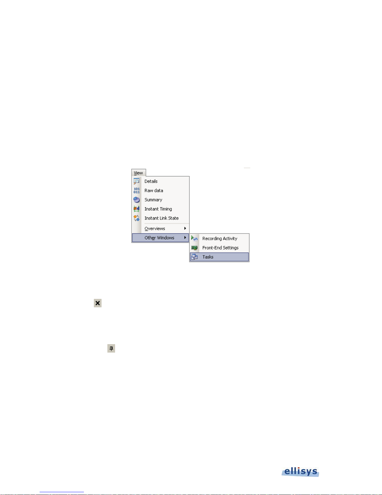
1. Select View in the menu and select the desired pane.
The selected pane opens.
To close a pane:
1. Click on Close
The pane closes.
To hide a pane:
1. Click on Auto-Hide
The pane is hidden and the pane’s name now appears as a tab at the right side of the screen.
To move a pane or a window:
1. Click on the title bar of the desired pane or window.
2. Depress and hold the left mouse button and drag the pane or window.
A window placer appears:
positioned at the top-right corner of the title bar of the pane.
positioned at the top-right corner of the title bar.
26 of 157 | Analyzer User Interface Reference
Page 27
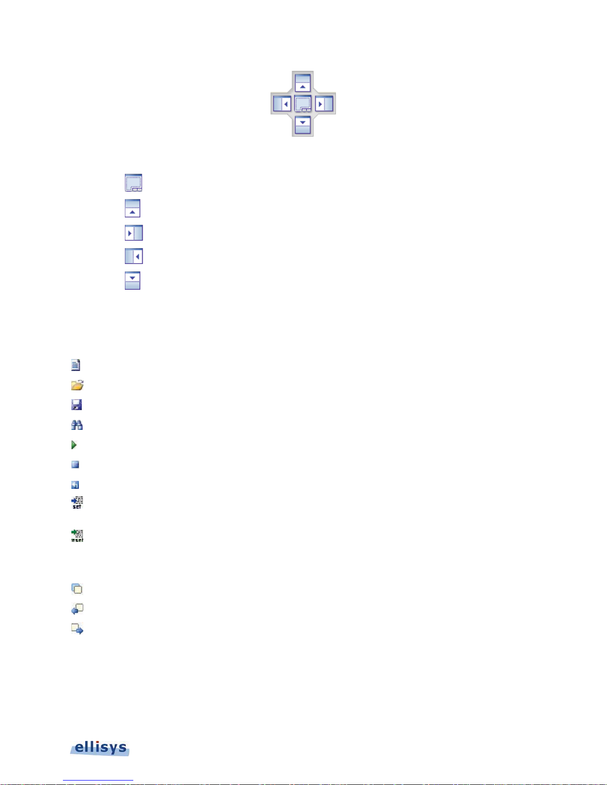
3. Keep the mouse button depressed and point to one of the following:
Center to open a pane as a floating window in the screen.
Top to move the pane to the top of the screen or pane group.
Right to move the pane to the right of the screen or pane group.
Left to move the pane to the left of the screen or pane group.
Bottom to move the pane to the bottom of the screen or pane group.
4.2 Main Toolbar
The table below shows the USB Explorer 350 Analyzer toolbar buttons and their actions:
New Creates a new empty capture file.
Open Opens a previously saved capture file.
Save Saves a capture file.
Search Opens the Search dialog.
Start Recording Starts a recording on the given Analyzer unit.
Stop Recording Stops the current recording.
Ellisys USB Explorer 350
Restart Abort the current recording and restarts a new one.
Set Time Reference
Reset Time Reference
Navigate Tracks user activity in Overviews for recall to past locations.
Markers Opens the markers menu.
Find Previous Marker Jumps to previous marker.
Find Next Marker Jumps to next marker.
Sets the time reference at the line selected in the
0.000.000.000
Resets the time reference at the line selected in the
original value.
Analyzer User Interface Reference | 27 of 157
USB 3.0 Overview
USB 3.0 Overview
at
to its
Page 28
4.3 Main Menu
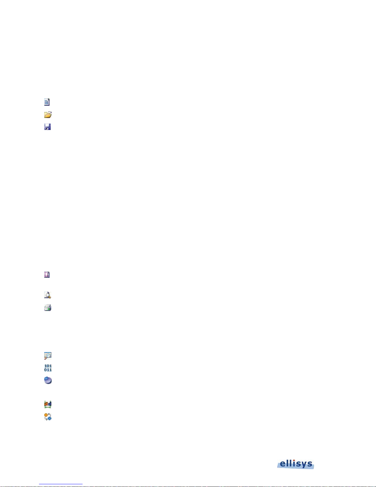
The table below shows the USB Explorer 350 Analyzer main menu options and their actions, with shortcuts shown in
parentheses:
File
New (CTRL+N) Creates a new recording session.
User Guide
Open (CTRL+O) Opens a folder to open a previously saved capture.
Save (CTRL+S) Saves a capture
Save As Saves an existing capture to a new name.
Load Sample Opens sample files provided with application.
Trace Information Provides information on trace file.
Share to Cloud Allows the user to securely share a saved capture to the Ellisys
cloud.
Retrieve from Cloud Allows the user to retrieve a shared capture from the Ellisys
cloud.
Import (Ctrl+P) Imports a file to view in the Analyzer application.
View
Export (Ctrl+E) Exports a trace to various formats.
Switch Workplace Allows user to switch to a different Workspace or to create a
new Workspace.
Import and Export Settings Opens the
Page Setup
Print Preview Opens the
Print Print the selected overview window.
Exit Closes the application.
Details Opens the
Raw Data Opens the
Summary Opens the
Errors Opens the
Instant Timing Opens the
Opens
other parameters.
Import and Export Settings Wizard
Page Setup
Print Preview
Details
Raw Data
Summary
Errors
Instant Timing
dialog allowing user to set page margins and
window.
pane.
pane.
pane.
Pane
pane.
.
Instant Link State Opens the
Instant Throughput Opens the
28 of 157 | Analyzer User Interface Reference
Instant Link State
Instant Throughput
pane.
pane.
Page 29

View | Overviews
Message Log Opens the
USB 2.0 Overview Opens the
USB 3.x Overview Opens the
USB PD Overview Opens the
View | Other Windows
Recording Activity Opens the
Front-End Settings Opens the
Tasks Opens the
Layout
New Layout Creates a new layout.
Rename Layout Renames the existing layout.
Reset Layout Resets the existing layout.
Delete Layout Deletes the existing layout (default layout excluded).
Search
Search (CTRL+F) Opens the
Message Log
USB 2.0 Overview
USB 3.x Overview
USB PD Overview
Recording Activity
Front-End Settings
Tasks
pane.
Find
menu.
.
pane.
pane.
Ellisys USB Explorer 350
Record
Search In Specifies the Overview in which to search.
Instant Search (CTRL+I) Places the cursor in the
Go To (CTRL+G) Opens the
Go To Next Expands a menu to enable search for next various USB items.
Go To Previous Expands a dialog to enable search for previous various USB
items.
Find Next (F3) Searches forward for the last event found in a search.
Start Recording (CTRL+R) Starts a recording.
Stop Recording (CTRL+SHFT+R) Stops the current recording.
Restart Recording Abort the current recording and restarts a new one.
Select an Analyzer Opens the
attached Analyzer to be used.
Recording Options Opens the
Go To Item
Available Analyzers
Recording Options
Instant Search
window.
dialog.
window.
dialog to allow for selection of
Analyzer User Interface Reference | 29 of 157
Page 30

Tools
Prepare Support Info Compresses files pertinent to Ellisys technical support. In some
cases, Ellisys may request these files.
Web Control Interface Options the Web Control tab of the
Set Time Reference (CTRL+T)
User Guide
Reset Time Reference
(CTRL+SHFT+T)
Options Open the
Help
Ellisys website Opens the Ellisys website in the default browser.
Contact support
Check for updates Checks online for the latest software version.
About Opens the
Options
permits remote, browser based control of the USB Explorer 350.
Sets the time reference at the line selected in the active
Overview
Resets the time reference at the line selected in the active
Overview
Opens a form in the default browser to contact Ellisys technical
support.
at 0.000.000.000
to its original value.
Options
About
menu.
window.
menu. Web control
30 of 157 | Analyzer User Interface Reference
Page 31
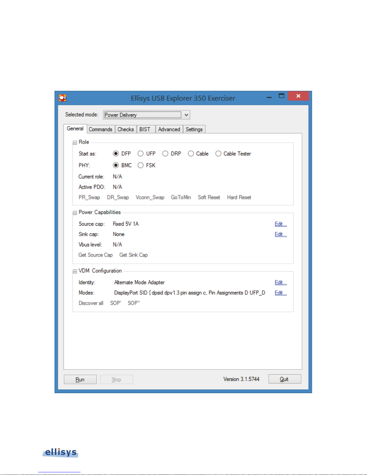
5. Exerciser User Interface
The user interface of the USB Explorer 350 Exerciser uses a tabular approach to expose features available for USB
3.x and USB Power Delivery. Various tabs are displayed. These will vary depending on the mode selected.
Ellisys USB Explorer 350
Figure 11 USB Explorer 350 Exerciser Interface
Exerciser User Interface | 31 of 157
Page 32

Selections Common to All Modes
Selected Mode
RUN Button
STOP Button
Quit Button
Version Number
General Tab
Commands Tab
Checks Tab
Commands Tab
BIST Tab
Advanced Tab
Settings Tab
General Tab
Advanced Tab
Settings Tab
USB 3
General Tab
S
3.x.
– Provides the user a choice of operating modes: USB Power Delivery or USB
User Guide
The Exerciser application displays a mode selection at the top (for USB Power Delivery or USB 3.x modes), several
selectable mode-specific tabs across the top, and common control features at the bottom. The various selections are
described below:
USB Power Delivery Mode
to check for new updates and download new updates. Will have a red background when a
new update is available online.
Defined Message (VDM) configurations, status indications, links to execute common
commands, physical media (FSK or BMC), and starting role selections.
Exerciser operation.
– Initiates operation of the Exerciser.
– Halts operation of the Exerciser.
– Closes the application.
– Indicates the current version number and when selected, allows the user
– Provides selections and definitions for Sink and Source capabilities, Vendor
– Provides a list of commands that can be selected and executed.
– Lists compliance checks that can be enabled and run in the background during
– Provides a list of commands that can be selected and executed.
USB 3.x LFPS Mode
.x Data Pump Mode
timing values.
of desired unit.
of desired unit.
common LFPS commands, and a port type selection.
– Provides various selections to enable BIST modes.
– Allows for control of certain physical layer parameters and well as stack
– Shows all available USB Explorer 350 units attached and allows for selection
– Provides selections and definitions for LFPS, SCD, and LBPM activities.
– Provides a list of editable timing parameters for various LFPS sequences.
– Shows all available USB Explorer 350 units attached and allows for selection
– Provides selections for speed (Gen1 or Gen2), link status, links to execute
32 of 157 | Exerciser User Interface
Page 33

Advanced Tab
Settings Tab
A
sequences, link training ordered sets, scrambling, SKP controls, and spread spectrum clocking
(SSC) enable/disable.
– Provides a list of editable timing, interval, and count parameters LFPS
of desired unit.
– Shows all available USB Explorer 350 units attached and allows for selection
Ellisys USB Explorer 350
Exerciser User Interface | 33 of 157
Page 34
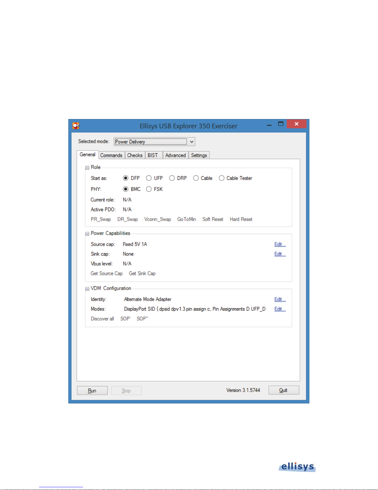
5.1 Power Delivery Settings and Controls
The USB Power Delivery settings and controls are described below.
General Tab
The General tab includes various selections to control starting role, power capabilities, and VDM features. Various
commands can be directly executed from this tab.
User Guide
34 of 157 | Exerciser User Interface
Figure 12 USB Power Delivery General Tab
Page 35

R
Role
Power Capabilities
VDM Configuration
Start As
DFP The Exerciser starts as a DFP
UFP The Exerciser starts as a UFP
DRP The Exerciser starts as a dual-role port
Cable The Exerciser starts as a cable
Cable Tester The Exerciser starts as a cable tester
Phy
BMC The Exerciser will use Bi-Phase Mark Coding
FSK The Exerciser will use Frequency Shift Keying
Current Role Displays the Exerciser’s current role
Active PDO Displays the active Power Delivery Object
PR_Swap Executes a Power Role Swap
DR_Swap Executes a Data Role Swap
VConn_Swap Executes a VConn Swap
GoToMin Executes a GoToMin transaction
Soft Reset Executes a Soft Reset
Ellisys USB Explorer 350
P
Source Cap Displays the current selection for the Exerciser’s Source
Capabilities, and allows for editing of these capabilities
(using Edit button)
Sink Cap Displays the current selection for the Exerciser’s Sink
Capabilities, and allows for editing of these capabilities
(using Edit button)
Vbus Level Displays the Vbus level
GetSourceCap Executes a GetSourceCapabilities message (while in
Sink Mode)
GetSinkCap Executes a GetSinkCapabilities message (while in
Source Mode)
V
Identity Using the Edit button, allows the user to configure the
Exerciser’s VDM Identity as Active Cable, Hub,
Peripheral, Passive Cable, or Peripheral
Modes Provide an interface to edit VDM Modes
Discover All Sends all VDM Discover commands (Discover Identity,
Discover SVID, Discover Modes)
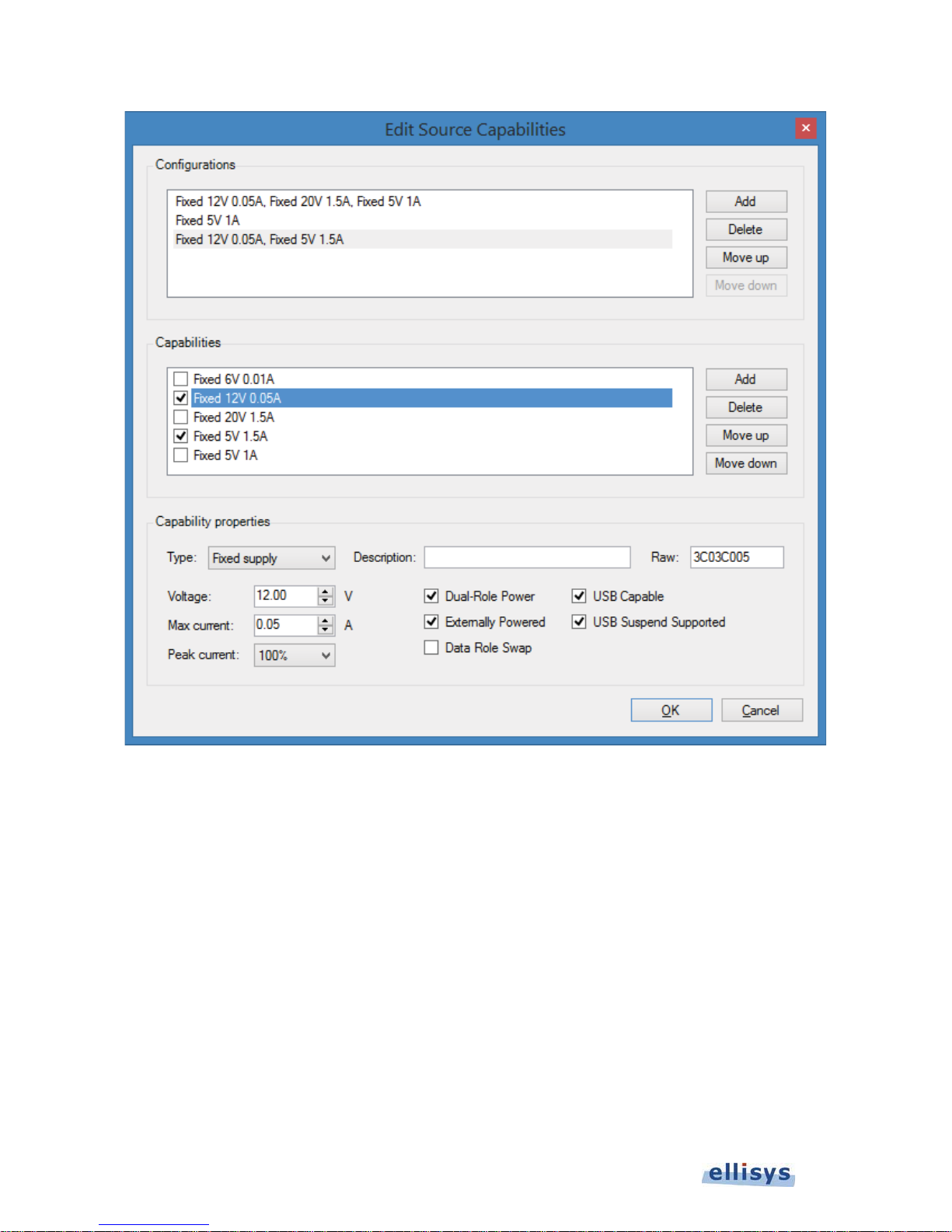
The Interface for defining Source Capabilities is described below. This is accessed by selecting the Source
Capabilities Edit button in the Power Capabilities section of the USB PD General Tab.
Exerciser User Interface | 35 of 157
Page 36
User Guide
36 of 157 | Exerciser User Interface
Figure 13 Source Capabilities Interface
Page 37

C
Configurations
Add
The Configurations section is populated using the A
button in this section, and configured for a
particular object by selecting one or more check boxes in the Capabilities section. The object
highlighted in this section is what will be used by the Exerciser.
Add Add a new capability
Delete Delete the selected capability
Move Up Move the selected capability up
Move Down Move the selected capability down
Capabilities
Capability
Properties
The Capabilities section is populated using the Add button in this section, and configured for a
particular object using the Capabilities Properties section.
Add Add a new capability
Delete Delete the selected capability
Move Up Move the selected capability up
Move Down Move the selected capability down
The Capability Properties section is populated using the various drop-down menus, check boxes,
and text-entry fields in this section.
Type Provides selections for Source Capabilities Power Data
Object (PDO) for Fixed Supply, Battery, Variable Supply, or
Reserved.
Description Allows the user to assign a text string (name) to a
particular capability property
Raw Hex input and display. Populated by entries made by the
user in this section. Can be used to populate reserved
fields with non-default values. May also be used to define
the full PDO in lieu of drop-down and check-box selections.
Fixed Supply Selects Fixed Supply as the PDO
Voltage Allows the user to specify a value in the Voltage field of the
Fixed Supply PDO
Max Current Allows the user to specify a value in the Maximum Current
field of the Fixed Supply PDO
Peak Current Allows the user to specify a value in the Peak Current field
of the Fixed Supply PDO
Dual-Role Power Sets the Dual-Role Power field in the PDO
Externally Powered Sets the Externally Powered field in the PDO
Data Role Swap Sets the Data Role Swap field in the PDO
USB Capable Sets the USB COMM Capable field in the PDO
USB Suspend Capable Sets the USB Suspend Supported field in the PDO
Ellisys USB Explorer 350
Battery Selects Battery as the PDO
Max Power Allows the user to specify a value in the Maximum Power
Min Voltage Allows the user to specify a value in the Maximum Voltage
Max Voltage Allows the user to specify a value in the Maximum Voltage
field of the Battery PDO
field of the Battery PDO
field of the Battery PDO
Exerciser User Interface | 37 of 157
Page 38
Variable Supply Selects Variable Supply as the PDO
Max Current Allows the user to specify a value in the Maximum Current
field of the Variable Supply PDO
Min Voltage Allows the user to specify a value in the Minimum Voltage
field of the Variable Supply PDO
Max Voltage Allows the user to specify a value in the Maximum Voltage
User Guide
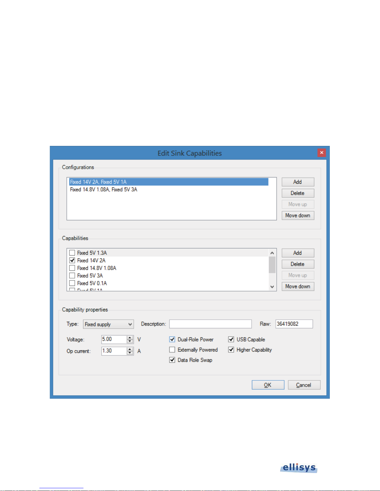
The Interface for defining Sink Capabilities is described below. This is accessed by selecting the Sink Capabilities
Edit button in the Power Capabilities section of the USB PD General Tab.
field of the Variable Supply PDO
38 of 157 | Exerciser User Interface
Figure 14 Sink Capabilities Interface
Page 39

Configurations
The Configurations section is populated using the A
Add
C
particular object by selecting one or more check boxes in the Capabilities section. The object
button in this section, and configured for a
highlighted in this section is what will be used by the Exerciser.
Add Add a new capability
Delete Delete the selected capability
Move Up Move the selected capability up
Move Down Move the selected capability down
Capabilities
Capability
Properties
The Capabilities section is populated using the Add button in this section, and configured for a
particular object using the Capabilities Properties section.
Add Add a new capability
Delete Delete the selected capability
Move Up Move the selected capability up
Move Down Move the selected capability down
The Capability Properties section is populated using the various drop-down menus, check boxes,
and text-entry fields in this section.
Type
Description
Raw
Fixed Supply Selects Fixed Supply as the Request Data Object (RDO)
Voltage
Op Current
Dual-Role Power Sets the Dual-Role Power field in the RDO
Externally Powered Sets the Externally Powered field in the RDO
Data Role Swap Sets the Data Role Swap field in the RDO
USB Capable Sets the USB COMM Capable field in the RDO
Higher Capability Sets the USB Suspend Supported field in the RDO
Provides selections for Sink Capabilities for Fixed Supply, Battery,
Variable Supply, or Reserved.
Allows the user to assign a text string (name) to a particular
capability property
Hex input and display. Populated by entries made by the user in this
section. Can be used to populate reserved fields with non-default
values. May also be used to define the full RDO in lieu of drop-down
and check-box selections.
Allows the user to specify a value in the Voltage field of the Fixed
Supply RDO
Allows the user to specify a value in the Operating Current field of
the Fixed Supply RDO
Ellisys USB Explorer 350
Battery Selects Battery as the RDO
Op Power
Min Voltage
Max Voltage
Variable Supply Selects Variable Supply as the PDO
Op Current
Allows the user to specify a value in the Operating Power field of the
Battery RDO
Allows the user to specify a value in the Maximum Voltage
field of the Battery PDO
Allows the user to specify a value in the Maximum Voltage field of
the Battery PDO
Allows the user to specify a value in the Operating Current field of
the Variable Supply PDO
Exerciser User Interface | 39 of 157
Page 40
Min Voltage
Max Voltage
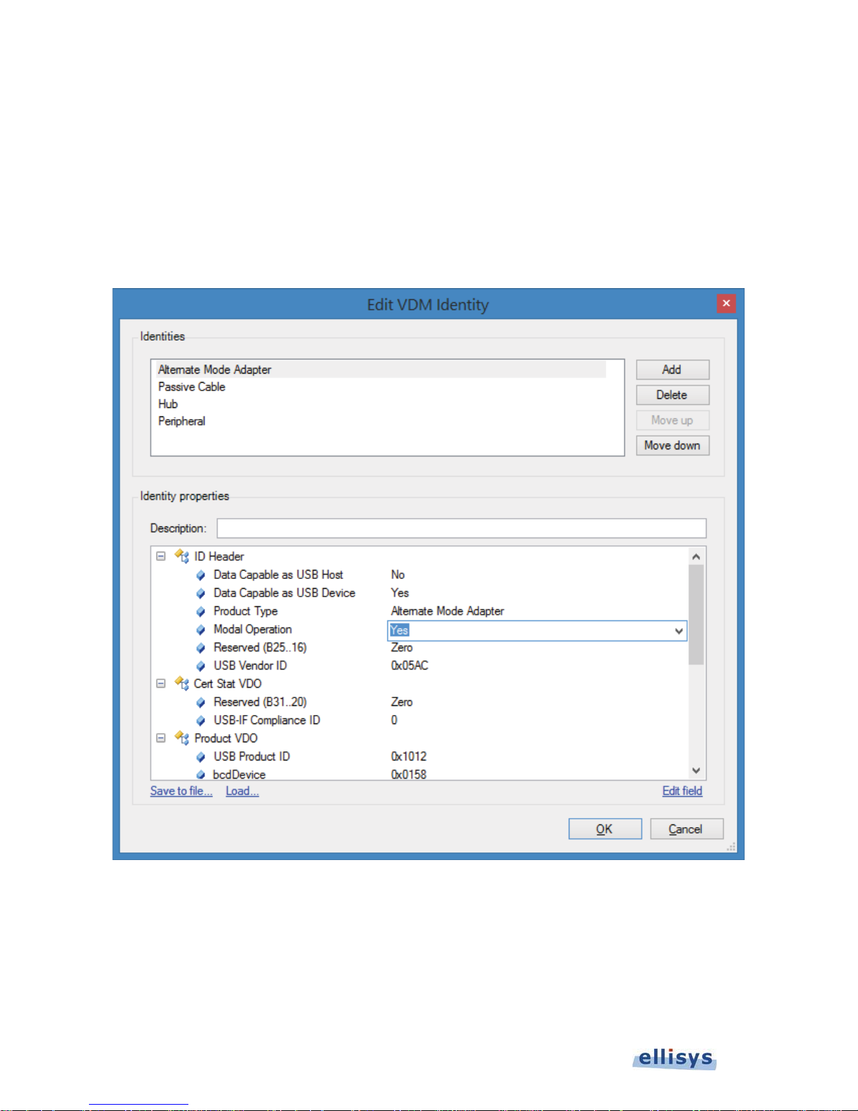
The Interface for defining the Exerciser’s VDM Identity is illustrated below. This is accessed by selecting the Identity
User Guide
Edit button in the VDM Configuration section of the USB PD General Tab.
Allows the user to specify a value in the Minimum Voltage field of
the Variable Supply PDO
Allows the user to specify a value in the Maximum Voltage field of
the Variable Supply PDO
The Interface for defining the Exerciser’s SVIDs and Modes is illustrated below. This is accessed by selecting the
Modes Edit button in the VDM Configuration section of the USB PD General Tab
40 of 157 | Exerciser User Interface
Figure 15 Edit VDM Identity
Page 41
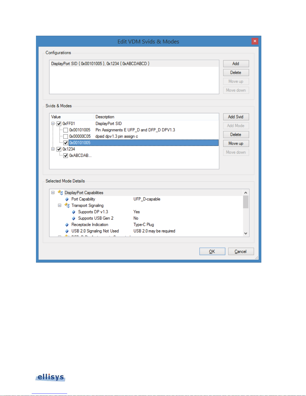
Figure 16 Edit VDM Modes
Ellisys USB Explorer 350
Exerciser User Interface | 41 of 157
Page 42
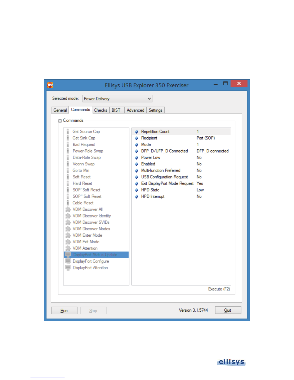
Commands Tab
Commands available in the Commands tab are executed using Keyboard F2 or by selecting the Execute (F2)
button on this page. Various attributes are available for each command selected, such as repetitions, SVIDs, and
other appropriate fields. These attributes are displayed at the right side of the page and are editable after selecting
the desired command.
User Guide
Figure 17 USB Power Delivery Commands Tab
42 of 157 | Exerciser User Interface
Page 43
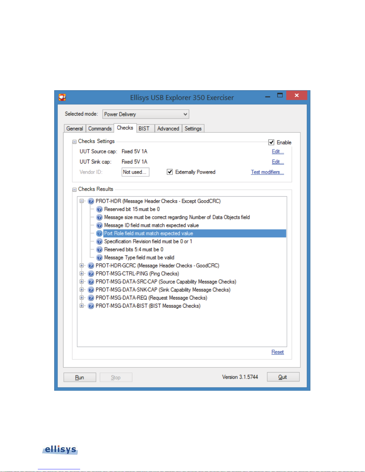
Checks Tab
The Checks tab provides the user the option to have the Exerciser monitor the traffic sequences or events and then
provide go and no-go indications on such sequences and events, should they occur. These checks are enabled only
when the Enable box is checked.
Ellisys USB Explorer 350
Figure 18 USB Power Delivery Checks Tab
Exerciser User Interface | 43 of 157
Page 44

Checks Settings
Enable Enables Checks to run (in the background).
UUT Source Cap
User Guide
UUT Sink Cap
Vendor ID Vendor ID Input
Externally Powered TBD
Test Modifiers TBD
Checks
Results
The Check Results section lists several categories of tests. As test conditions are “seen” by the
Checks engine (the software running in the background looking for these conditions), the individual
checks will be assigned pass or fail indications.
TBD
Reset Resets the pass and fail indications that have been accumulated.
Indicates the current Source Capabilities and provides an Edit
button to change these settings.
Indicates the current Sink Capabilities and provides an Edit button
to change these settings.
The Checks engine has not seen a condition to test an item.
The Checks engine has seen a condition to test an item and the
item has passed.
The Checks engine has seen a condition to test an item and the
item has failed.
BIST Tab
The BIST tab enables BIST specific testing modes. The user is provided selections to define the test type, recipient
(SOP, SOP’, SOP”) as well as test start and stop (via Hard Reset). Note th at not all modes are supported by all USB
Power Delivery devices.
44 of 157 | Exerciser User Interface
Page 45
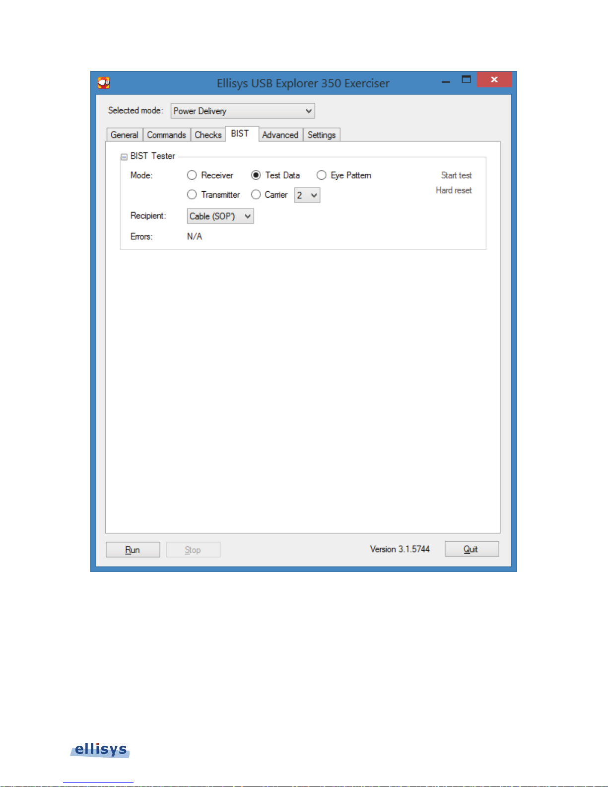
Figure 19 USB Power Delivery BIST Tab
Ellisys USB Explorer 350
Exerciser User Interface | 45 of 157
Page 46

BIST Tester
Mode Receiver
Transmitter
User Guide
Test Data
Eye Pattern
Carrier Mode 0 The Exerciser sends a continuous string of "0"s.
Start Test Initiates the selected BIST Mode.
Hard Reset
The Exerciser sends BIST Receiver Test Frames with 1024 bits of
PRBS payload.
The Exerciser sends a BIST Transmitter Test Frame to initiate BIST
Transmitter mode in the far-end transmitter.
The Exerciser sends the Test Data frame with BIST Test Data BDO,
Data Objects = 7, and 192 bits (28 bytes) of PRBS data. BMC
required.
The Exerciser sends a continuous string of bits (PRBS-8). This
produces a signal that will allow measurement of the eye pattern and
of the spectrum mask.
Mode 1 The Exerciser sends a continuous string of "1"s.
Mode 2
Mode 3
The Exerciser sends a continuous string of alternating "1"s and “0”s.
BMC required.
The Exerciser sends a continuous string of sixteen "1"s, followed by
sixteen “0”s, followed by sixteen “1”s, etc.
The Exerciser sends a Hard Reset (used to exit the active BIST
Mode).
Recipient Specifies the recipient device type (SOP, SOP’, SOP”).
Errors
Provide a running count of errors detected in Transmitter or Receiver
BIST modes. Initialized to zero at test start.
46 of 157 | Exerciser User Interface
Page 47
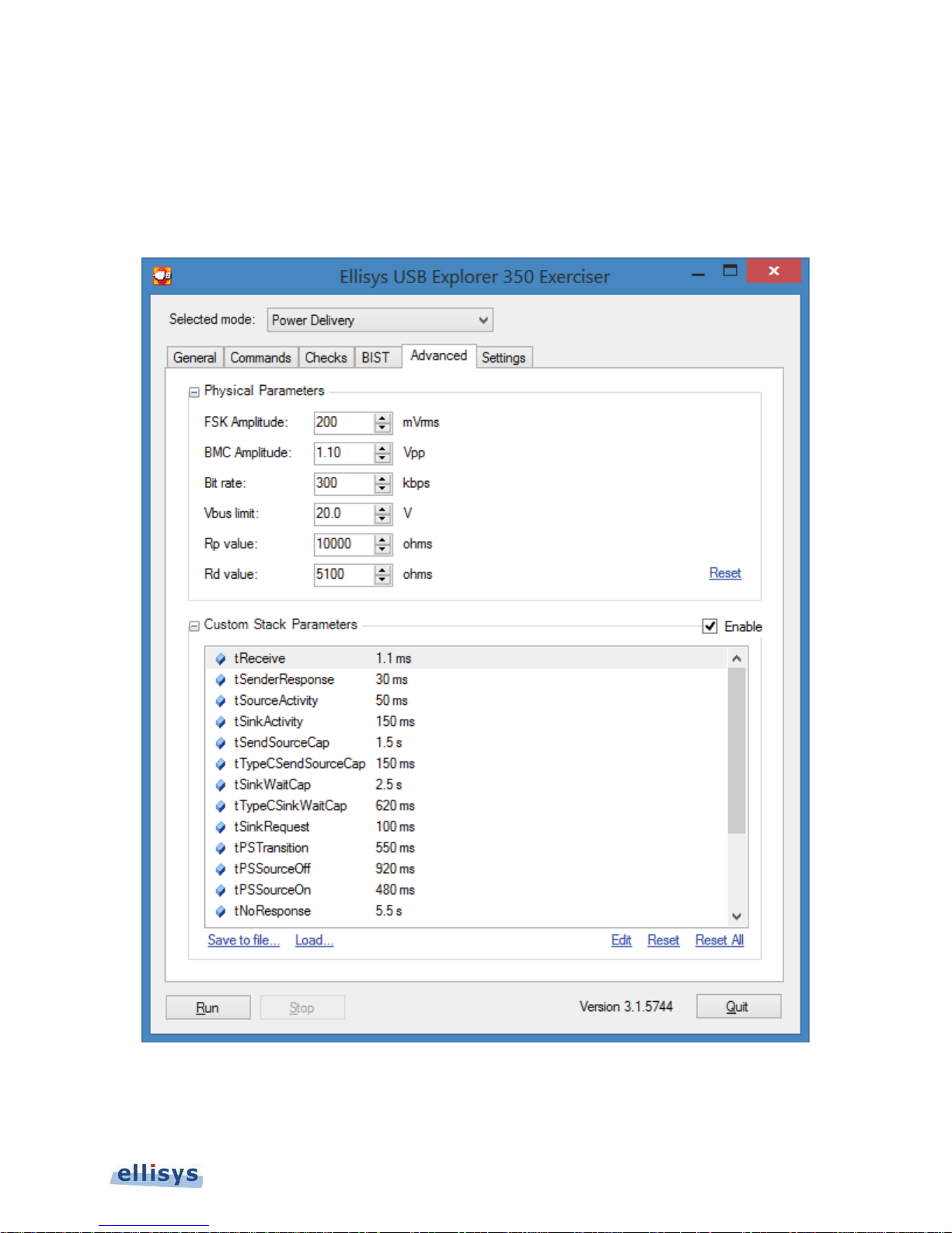
Advanced Tab
The Advanced tab provides the user with the ability to adjust physical parameters as well as parameters used by
the Ellisys stack. These selections allow for corner case testing of certain timers, counters, signaling voltages, and
the bit rate. An ability to limit voltage supplied by the USB Explorer in generator mode regardless of contract
parameters is provided.
Ellisys USB Explorer 350
Figure 20 Exerciser Advanced Tab
Exerciser User Interface | 47 of 157
Page 48

Physical
Parameters
User Guide
Custom Stack
Parameters
FSK Amplitude Allows for adjustment in the Exerciser’s FSK amplitude.
BMC Amplitude Allows for adjustment in the Exerciser’s BMC amplitude.
Bit Rate Allows for adjustment in the Exerciser’s bit rate.
Vbus Limit Limits the voltage supplied by the Exerciser on Vbus
irrespective of the contract negotiated.
Rp Value Allows the user to set a specific value for Rd, in Ohms.
Rd Value Allows the user to set a specific value for Rp, in Ohms.
Reset Resets the amplitude and bit rate settings to nominal values.
Parameter Spec Reference
tReceive 6.5.1
tSenderResponse 6.5.2
tSourceActivity 6.5.3.1
tSinkActivity 6.5.4.1
tSendSourceCap
tTypeCSendSourceCap
tSinkWaitCap 6.5.4.2
tSinkRequest 6.5.5
tPSSourceTransition 6.5.6.1
tPSSourceOff 6.5.6.2
tPSSourceOn 6.5.6.3
tNoResponse 6.5.7
tSRCRecover
tSwapRecover
tBISTReceive 6.5.8.5
tBISTMode 6.5.8.1
tBISTContMode
nRetry Count 6.6.2
Save to File Saves the parameters to a file for recall.
Load Loads a saved file containing parameters.
Edit Allows for editing of selected parameter.
Reset Sets selected parameter to default value.
Reset All Sets all parameters to default values.
48 of 157 | Exerciser User Interface
Page 49
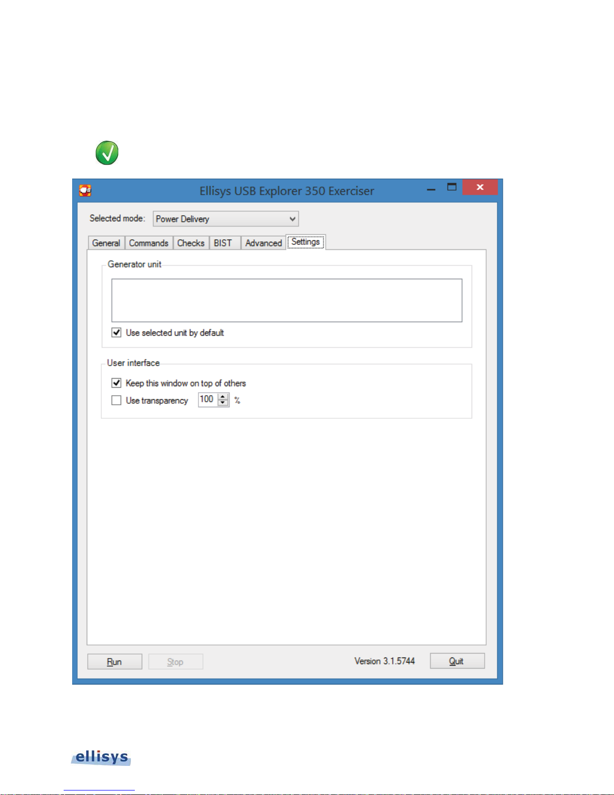
Settings Tab
The Settings Tab lists all connected USB Explorer 350 units. A selection is available to keep the Exerciser GUI on
top of other windows and another selection allows for the selection of window transparency.
Placing the mouse pointer over a serial number in the Settings Tab will cause the DC/PWR
IN/USB Control LED to flash white.
Ellisys USB Explorer 350
Figure 21 Exerciser Settings Tab
Exerciser User Interface | 49 of 157
Page 50
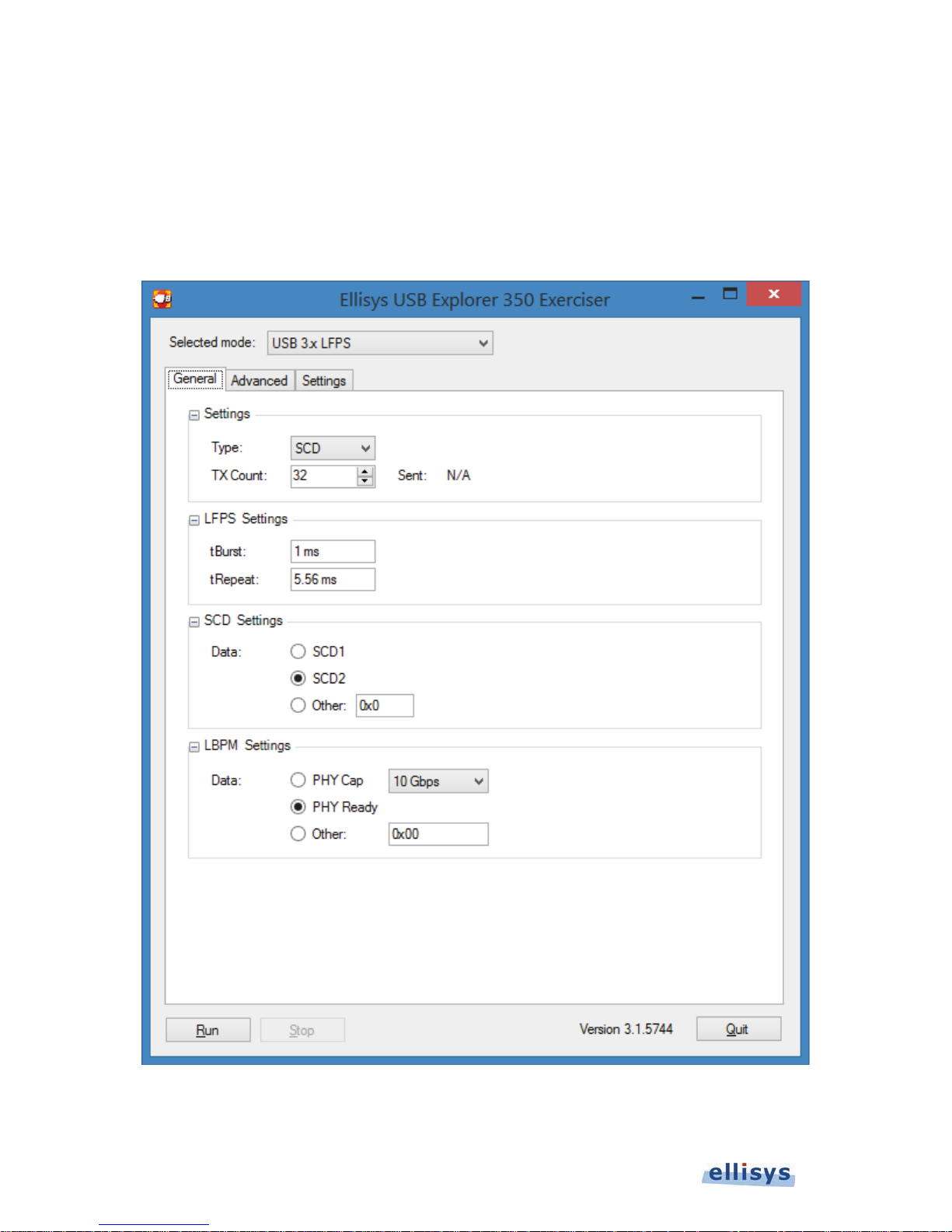
5.2 USB 3.x LFPS Settings and Controls
General Tab
The USB 3.x LFPS General tab includes various selections to control LFPS parameters.
User Guide
Figure 22 USB 3.x LFPS Settings and Controls
50 of 157 | Exerciser User Interface
Page 51

S
Settings
LFPS Settings
SCD Settings
Type
LFPS Selects SuperSpeed LFPS cycles for transmission
SCD Selects SuperSpeed Plus SCD patterns for transmission
LBPM Selects SuperSpeed Plus LBPM patterns for transmission
L
S
LBPM Settings
TX Count
Sent Indicates a running count of patterns transmitted
tBurst Provides for definition of LFPS tBurst duration
tRepeat Provides for definition of LFPS tRepeat duration
Data
SCD1 Select SCD1 for transmission (0010)
SCD2 Select SCD1 for transmission (1101)
Other Custom definition for SCD transmission
Data
Phy Cap Select Phy Capabilities for LBPM
Phy Ready Select Phy Ready for LBPM
Other Define custom value for LBPM data
Specifies the number of patterns selected in Type field
to be sent (up to 64K)
Ellisys USB Explorer 350
Exerciser User Interface | 51 of 157
Page 52
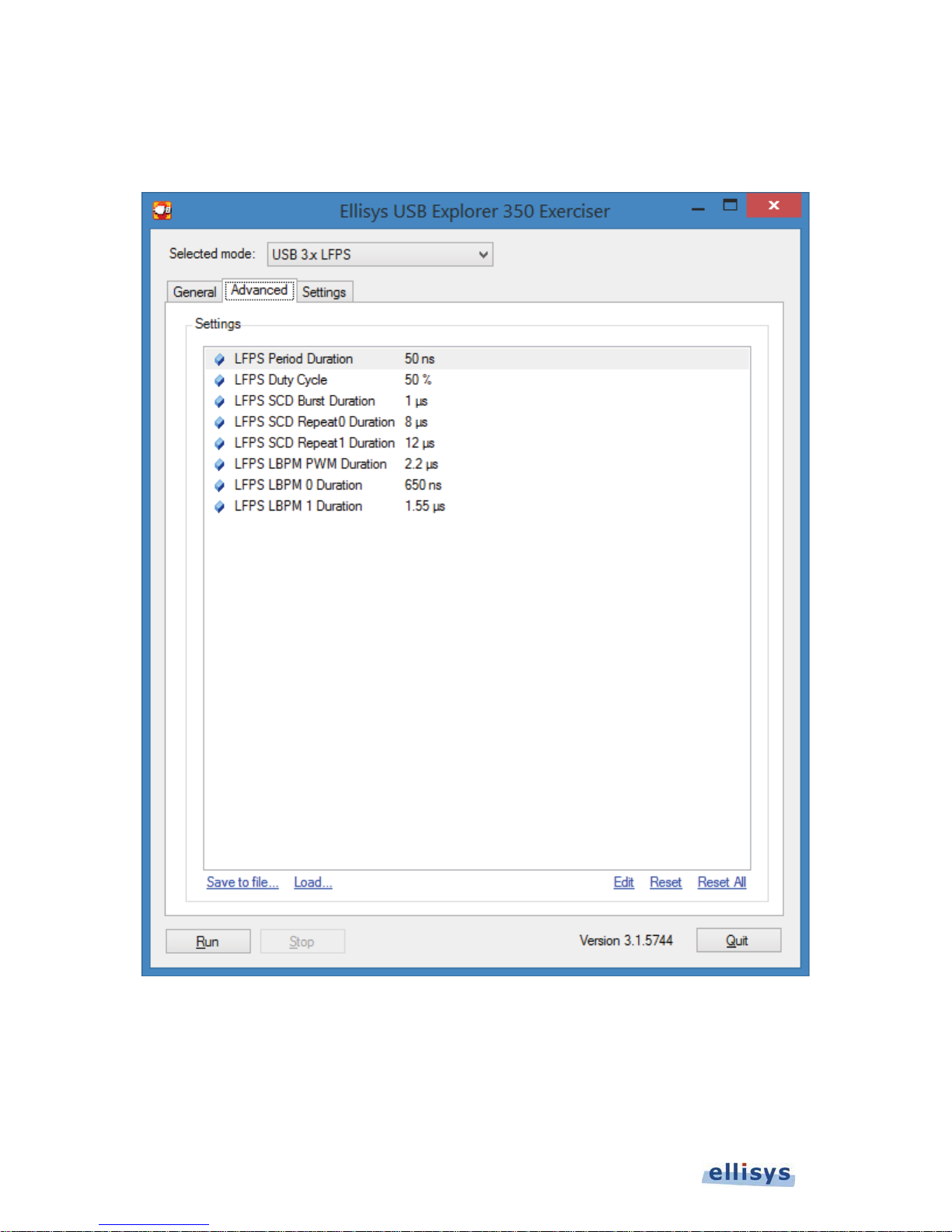
Advanced Tab
The USB 3.x LFPS Advanced tab allows the user to control the Exerciser’s various LFPS timing characteristics.
User Guide
52 of 157 | Exerciser User Interface
Figure 23 USB 3.x LFPS Advanced Tab
Page 53
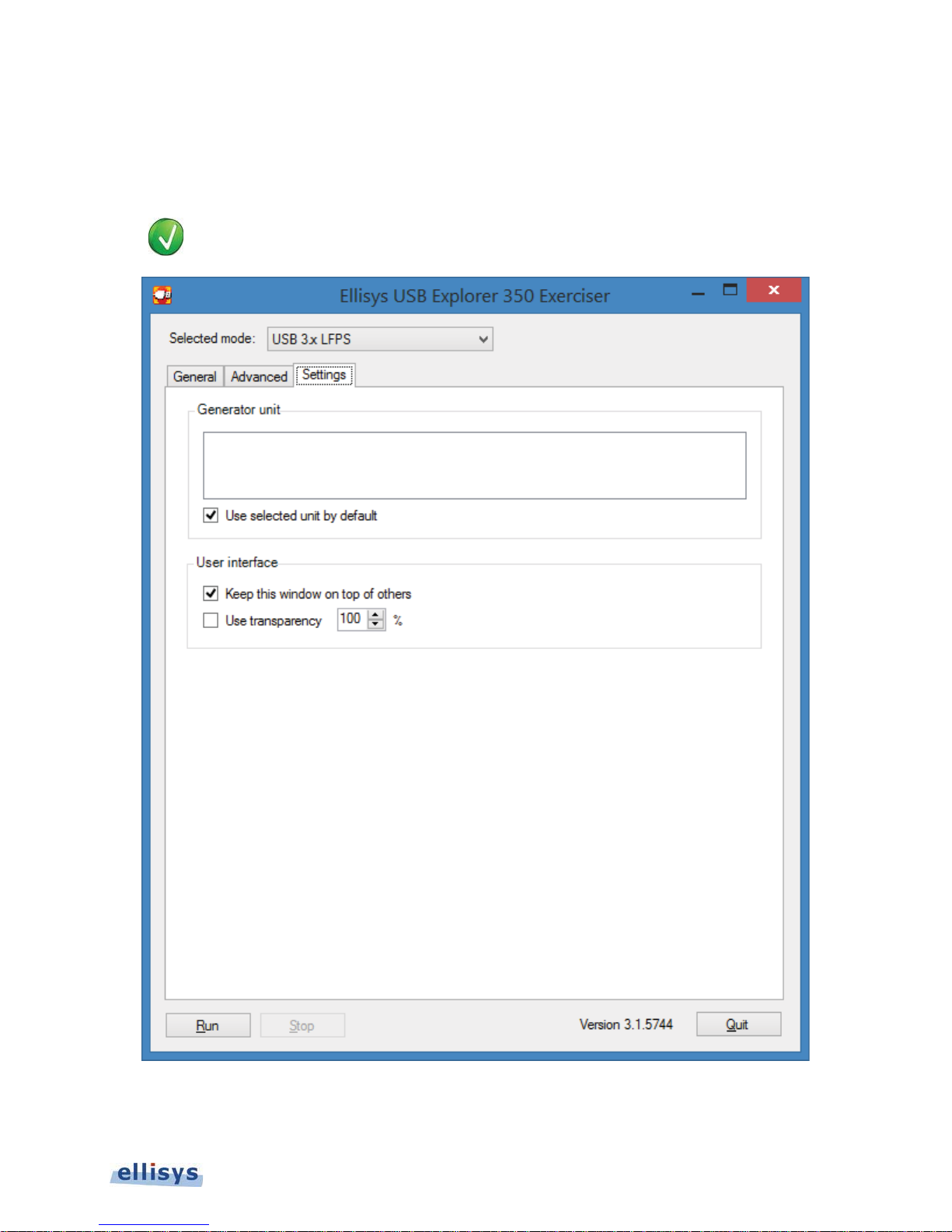
Settings Tab
The Settings Tab lists all connected USB Explorer 350 units. A selection is available to keep the Exerciser GUI on
top of other windows and another selection allows for the selection of window transparency.
Placing the mouse pointer over a serial number in the Settings Tab will cause the DC/PWR
IN/USB Control LED to flash white.
Ellisys USB Explorer 350
Figure 24 USB 3.x Settings Tab
Exerciser User Interface | 53 of 157
Page 54
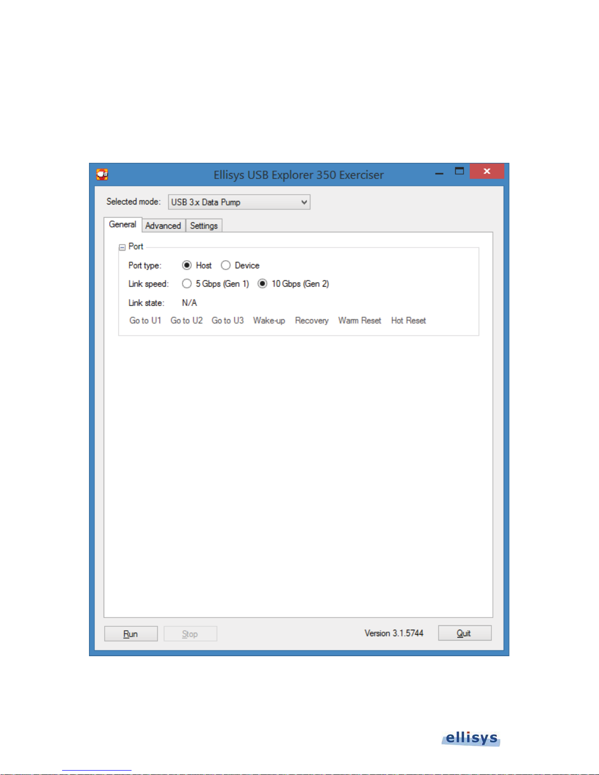
5.3 USB 3.x Data Pump Settings and Controls
General Tab
The General Tab provides basic settings to control the Exerciser’s mode. Various command execution links are
available as well as a port type selection (host or device) and a link state indication.
User Guide
54 of 157 | Exerciser User Interface
Figure 25 USB 3.x Data Pump General Tab
Page 55
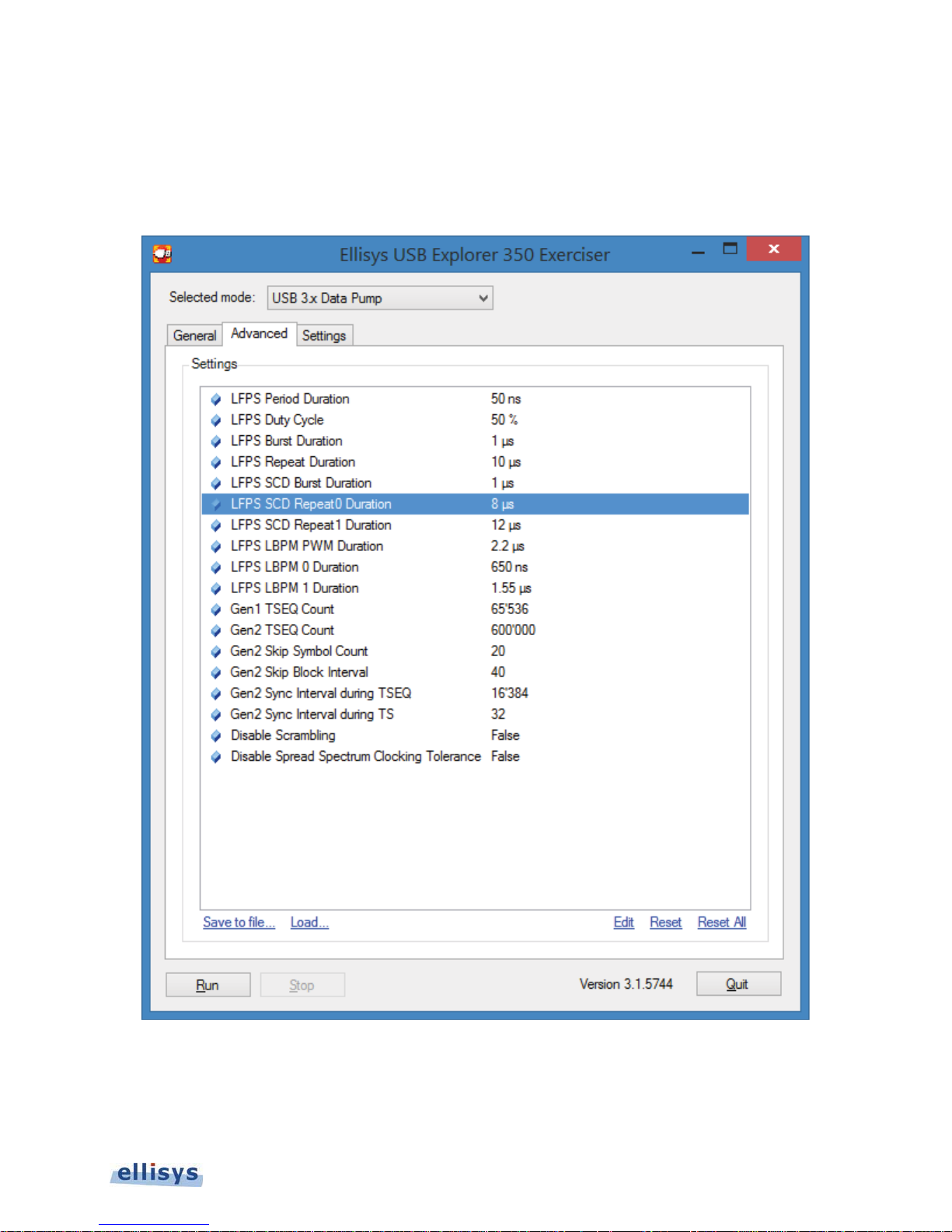
Advanced Tab
The Advanced Tab provides various controls relating to the Exerciser’s link training, SKP Rates, and other behaviors
and characteristics. Settings can be saved and loaded as needed. Settings can also be individually or collectively
reset to default.
Ellisys USB Explorer 350
Figure 26 USB 3.x Data Pump Advanced Tab
Exerciser User Interface | 55 of 157
Page 56
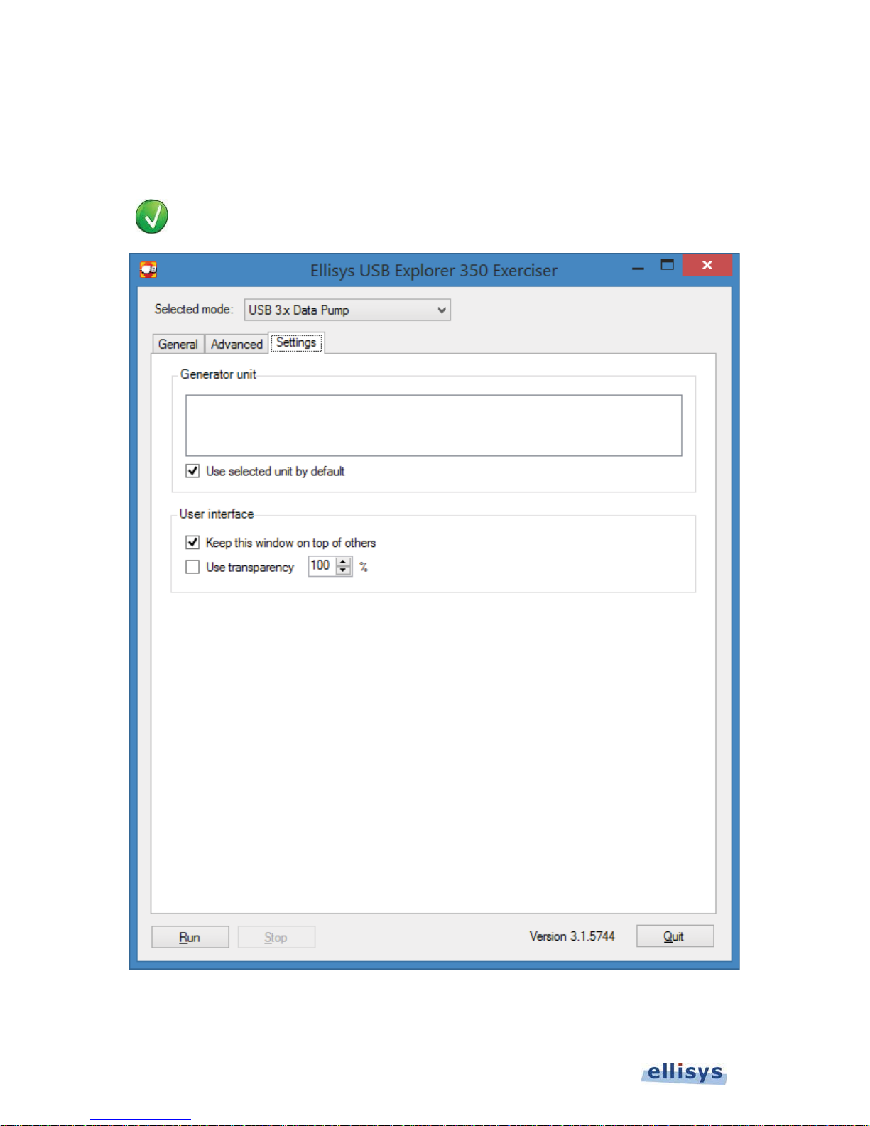
Settings Tab
The Settings Tab lists all connected USB Explorer 350 units. A selection is available to keep the Exerciser GUI on
top of other windows and another selection allows for the selection of window transparency.
Placing the mouse pointer over a serial number in the Settings Tab will cause the DC/PWR
IN/USB Control LED to flash white.
User Guide
56 of 157 | Exerciser User Interface
Figure 27 USB 3.x Data Pump Settings Tab
Page 57
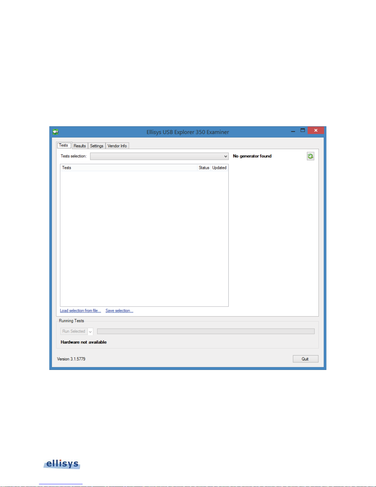
6. Examiner User Interface
The Examiner application’s user interface is comprised of a set of tabs that provide for user input, as well as real-time
indications of test activity and results. Test selection is available on the Tests tab.
Test setup is done in the same manner the user would set up as the Exerciser mode, either direct from the Examiner
unit to the UUT, or with the analyzer in between the Examiner unit and the UUT. See Section 20 Exerciser or
Examiner – Setting Up.
Ellisys USB Explorer 350
Figure 28 Examiner User Interface (Tests Tab Shown)
Tests Tab
The
Tests
tab allows the user to select one or more tests from several test categories. Test categories are shown in
the main
Tests Selection
Tests
window and selected individually using the associated check boxes there, or in groups, using the
drop-down selection.
Examiner User Interface | 57 of 157
Page 58
At the right side of the
T
Test Information that will be printed in the Summary Report produced at the end of testing.
ake care to select the correct UUT Type as the incorrect selection may cause false failures.
The version number at lower-left of the Tests tab indicates the present version and may also be clicked by the user
to check for availability of new application updates.
Tests
tab, the user may select the UUT Type, declare Accessory Support, and provide
User Guide
Tests are initiated with the Run button, which also provides an alternate selection to run only tests that have failed
in the prior run.
Results Tab
Results
The
information. The
a
Show Report…
tab shows a running summary of tests being executed, including pass/fail results and other related test
Results
button appears at lower-right to allow the user to open the
tab will open automatically when tests are executed by the user. When testing completes,
Summary Report
.
58 of 157 | Examiner User Interface
Page 59
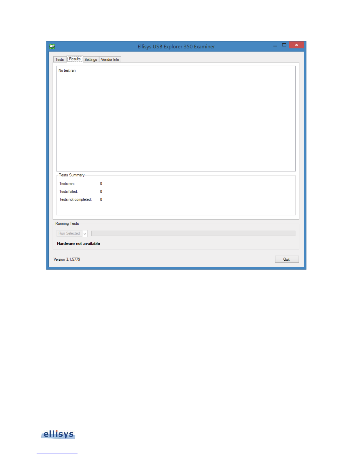
Figure 29 Examiner Results Tab
Traces
If an analyzer was used (selected in the Settings tab), a
user may open traces of interest (a trace is saved for each test executed). Traces may also be opened directly from
the report using the
trace
selection associated with each test.
button also appears when testing completes, so the
Ellisys USB Explorer 350
Examiner User Interface | 59 of 157
Page 60
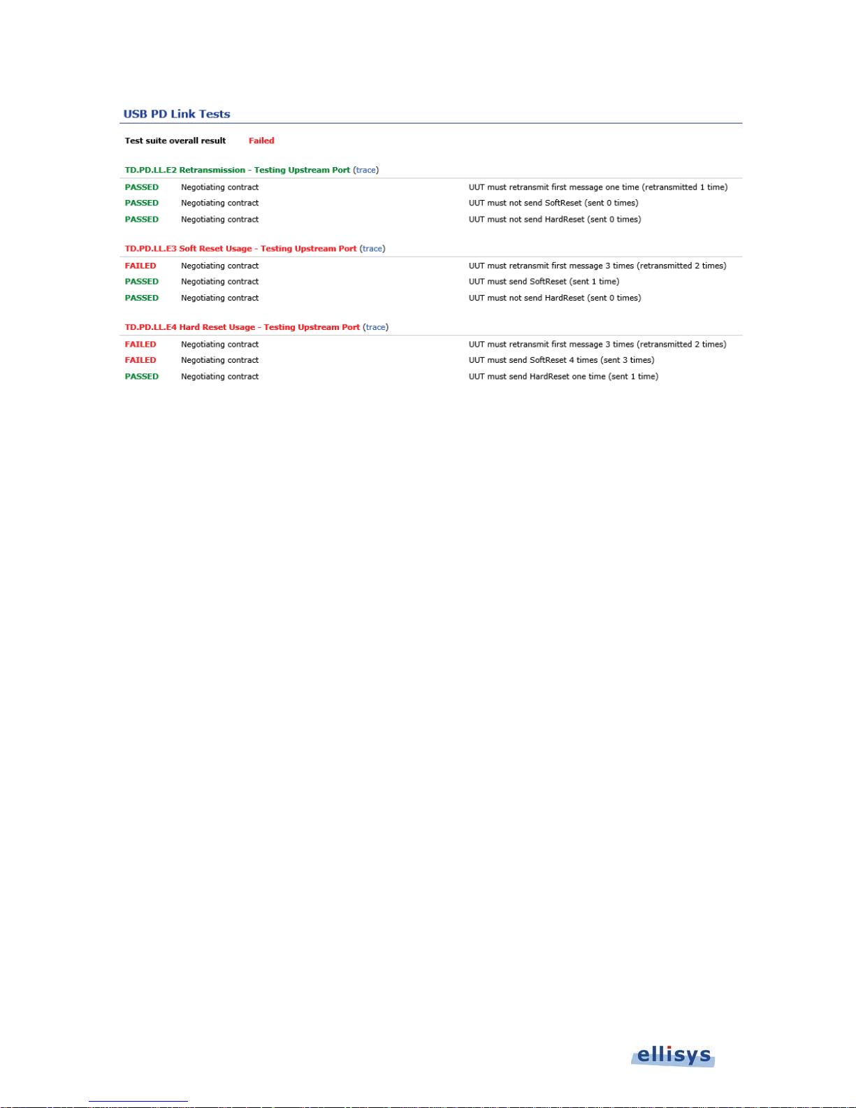
User Guide
Settings Tab
Figure 30 Sample Summary Report
Settings
The
unit executing the tests) or Analyzer unit. An Identify button associated with any connected units can be used to
create an LED flash on the unit associated with the adjacent serial number.
Reports created at the end of test execution are stored in the directory specified by the user in the Browse box. If
an analyzer unit is also used, associated analyzer traces are also stored in this directory.
For setups where both an Examiner unit is used and an Analyzer unit is used: The user can elect to have the
analyzer automatically capture traces for each test by checking the Analyzer box. Alternatively, this box can be left
unchecked and the analyzer can be operated under the control of the Analyzer application as Examiner executes the
selected test(s).
tab is used to select the hardware units (by serial number) that will perform as the Generator unit (the
60 of 157 | Examiner User Interface
Page 61
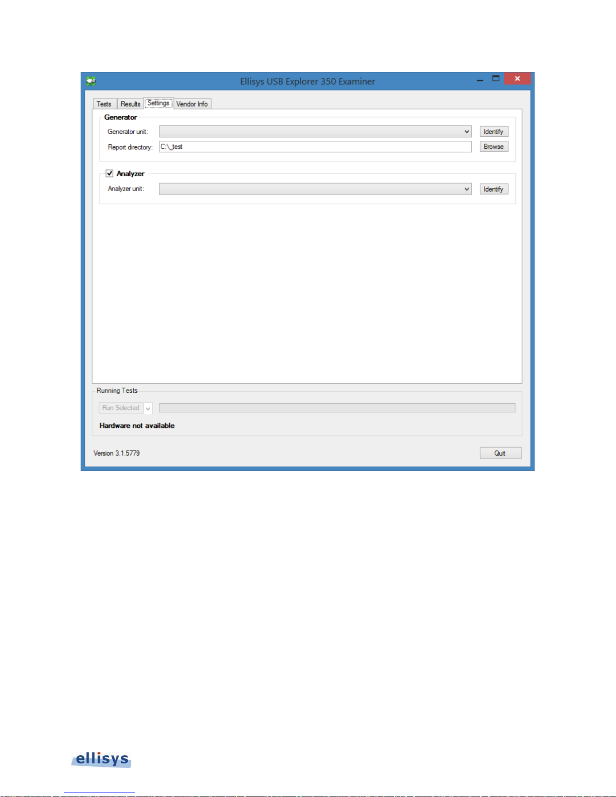
Figure 31 Examiner Settings Tab
Ellisys USB Explorer 350
Examiner User Interface | 61 of 157
Page 62
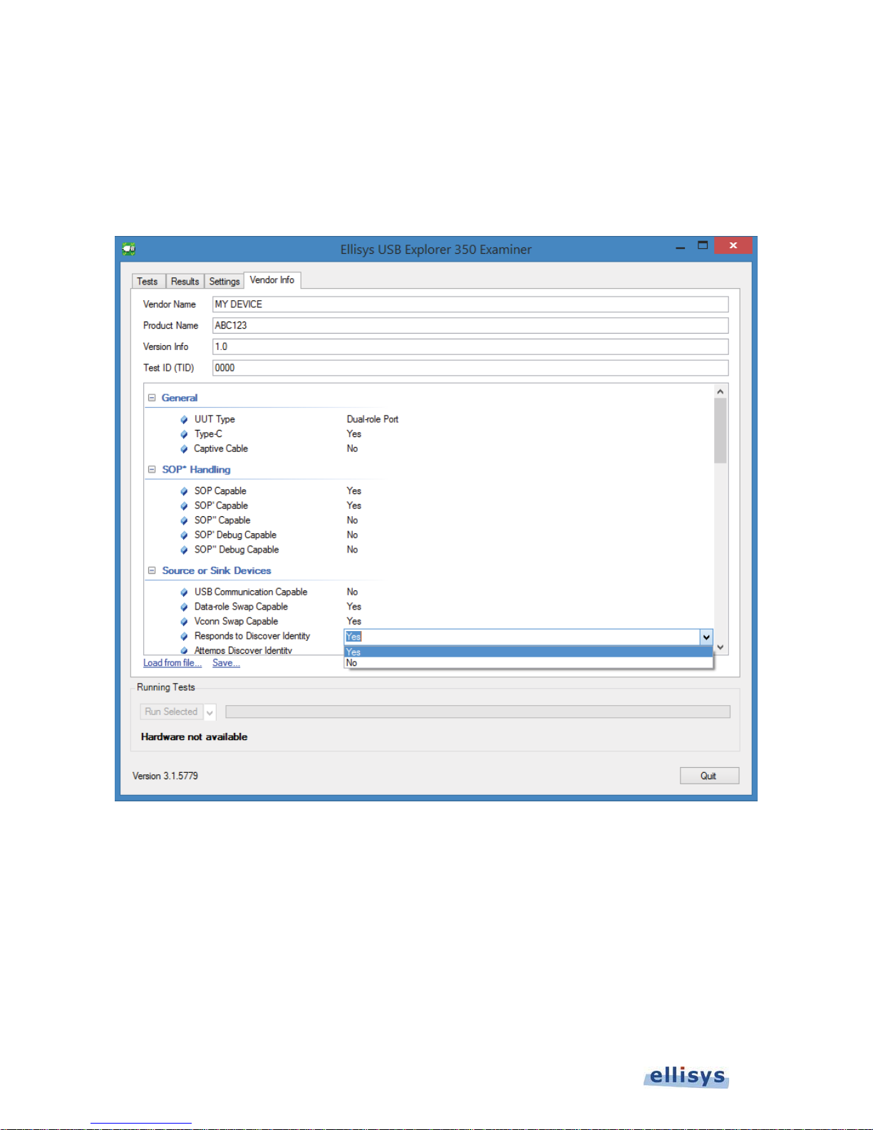
Vendor Info Tab
Vendor Info
The
the
Tests
using the
file.
tab lists the UUT’s various characteristics, which are confirmed in the
tab. The characteristics can be imported from a text file using the
Save
… selection. A new text file can be created by selecting the desired characteristics, then saving the
User Guide
Consistency
Load from File
tests available on
… selection, and saved
62 of 157 | Examiner User Interface
Figure 32 Settings Tab
Page 63
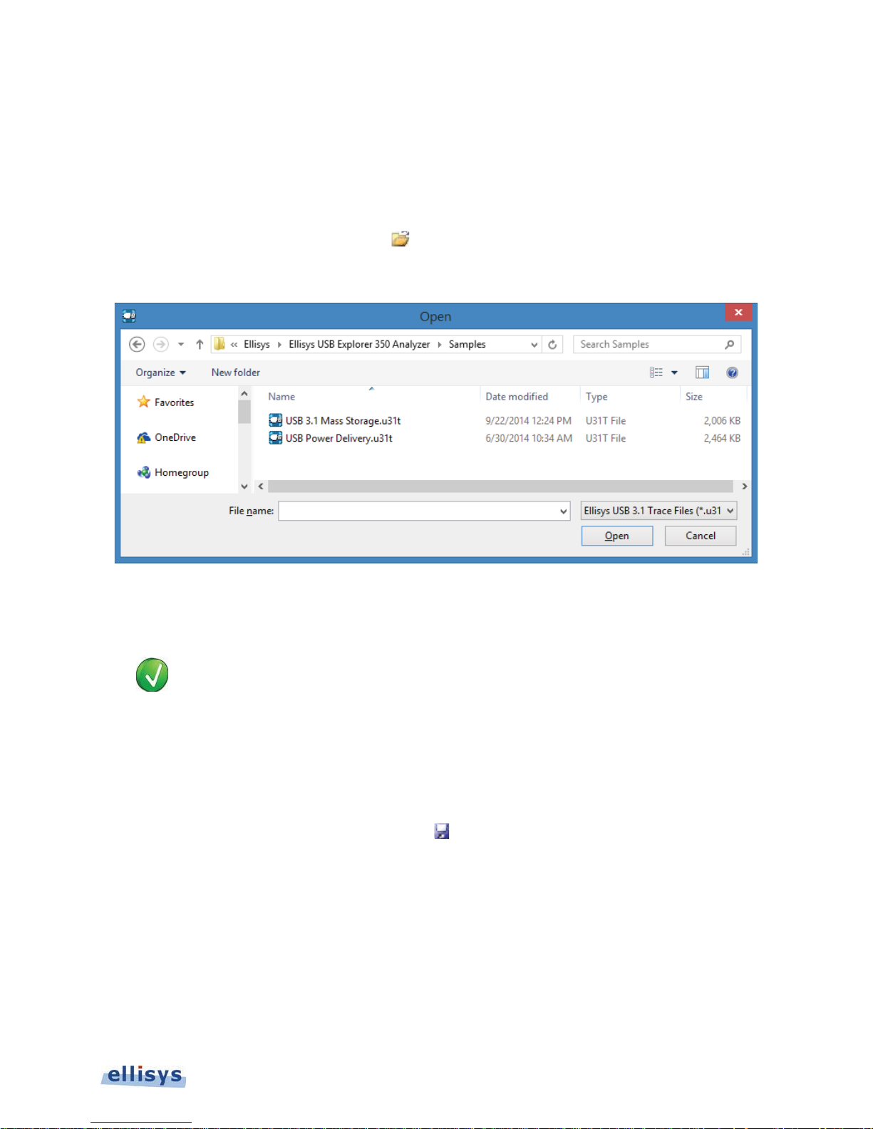
7. Analyzer Trace File Management
7.1 Opening a Trace File
To open a trace file:
Select File |Open in the menu or click on Open.
Open
The
menu appears:
Ellisys USB Explorer 350
1. Select the file required and click Open.
The selected file opens in the software.
Sample captures are available from File | Load Sample.
7.2 Saving a Trace File
To save a trace file:
1. Select File | Save As in the menu or click on Save.
The file is saved.
To save a trace file with a new name:
Select File | Save As in the menu.
Analyzer Trace File Management | 63 of 157
Page 64
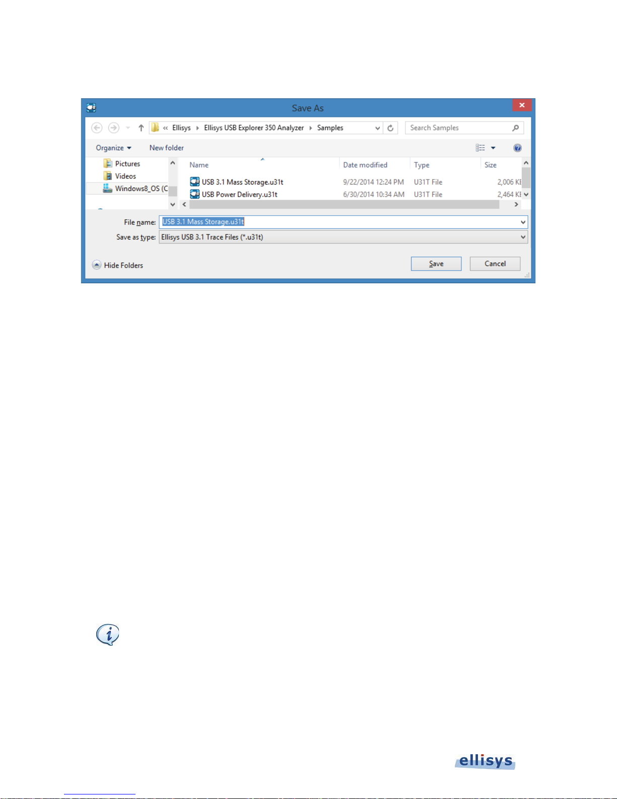
The
A
Save As
menu appears:
User Guide
1. Navigate to the directory where the file is to be saved.
2. Enter the desired name of the file in the File name field and click on Save.
The file is saved with the modified name and the original file is not modified.
7.3 Opening a Sample Trace File
Several sample trace files are included with the application.
To open a sample file:
1. Select File | Load Sample in the menu.
2. Click on the desired sample.
7.4 Printing a Trace File
Use the
on the printer; please see your printer’s documentation for more information.
To preview a print job:
1. Select File | Print Preview from the menu and select the desired Overview
Page Setup
option, File | Page S etup, to setup how the trace should be printed. This option will depend
file can be very large. Therefore, it is advisable to check the size of the file before trying to
print the file.
64 of 157 | Analyzer Trace File Management
Page 65
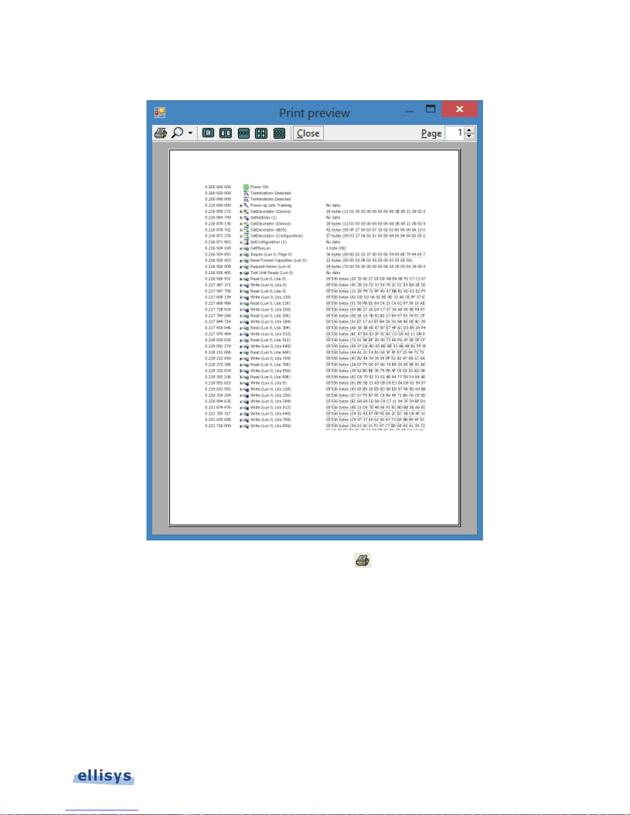
The
Print preview
window appears:
Ellisys USB Explorer 350
2. Print directly from the
Or
Click on Close to return to the trace file.
To print a file:
1. Select File | Print in the menu then select the desired Overview.
Print preview
window using the print icon .
Analyzer Trace File Management | 65 of 157
Page 66
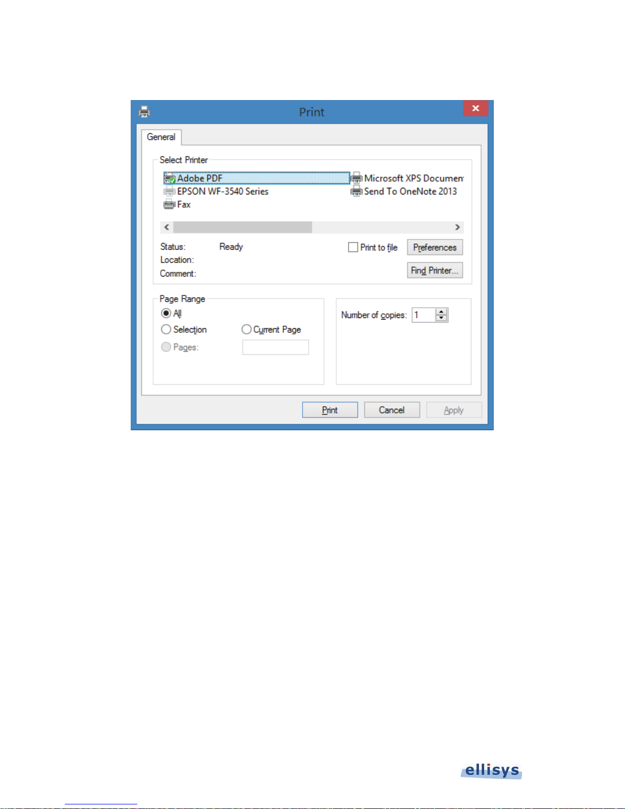
The
Print
window appears:
User Guide
2. Select the printer and printer setup if required.
3. Click on OK.
The file is printed.
7.5 Importing Data to View in a Trace File
The application permits the user to import data from formatted text files for display in the Ellisys viewer format. The
Analyzer hardware is not required for these operations.
Data can be imported from a packet and ordered set format or from a character-based format. Additional support is
provided to import Ellisys VisualUSB files (*.ufo).
66 of 157 | Analyzer Trace File Management
Page 67
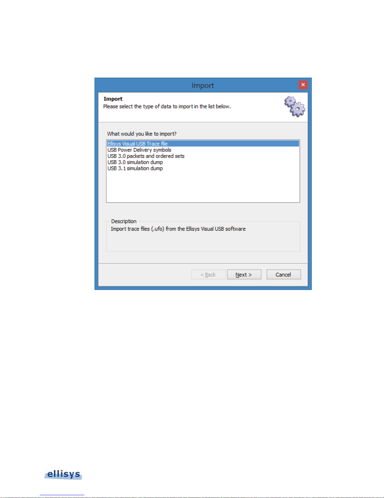
To access the Import menu:
The
Import
menu appears:
Ellisys USB Explorer 350
1. Select the desired import option.
2. Click on Next then follow the prompts to define the import desired.
7.6 Exporting a Trace File
A trace file can be exported for various ancillary purposes and in several formats. Format-based exports are
available in XML, CSV, text, and binary.
To access the Export menu:
1. Select File | Export from the menu.
Analyzer Trace File Management | 67 of 157
Page 68
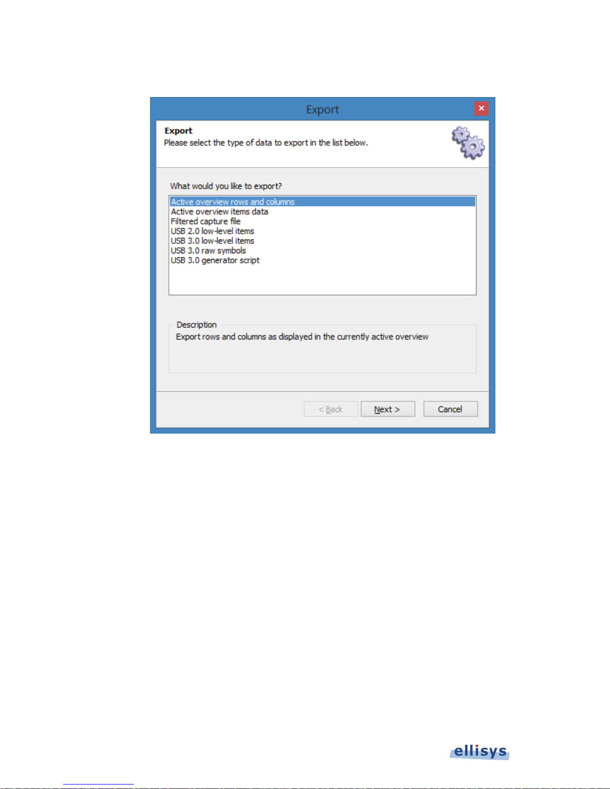
The
Export
menu appears:
User Guide
2. Select the desired Export option.
3. Click on Next and follow the prompts the complete the desired export.
68 of 157 | Analyzer Trace File Management
Page 69

8. Analyzer Workspaces and Layouts
8.1 Using Workspaces
The application allows the user to define a Workspace, which is a way of saving different sets of user settings
preferences, such as display settings and other settings like recording options, window layouts and protocol
verifications options. A default Workspace is provided by the application, but users may create and save new
Workspaces as desired. A non-exhaustive list of items affected by Workspace setting is shown below:
General options
Window layouts
Most recently used (MRU) files
Recording options
Injection API
Message Logs
USB 2.0 Overview
USB 3.x Overview
USB PD Overview
Details view
Raw data view
Summary view
Instant Throughput view
Instant Timing view
Ellisys USB Explorer 350
To create a new Workspace:
1. Select File | Switch Workspace from the menu.
The
Workspace
2. Click on New.
menu appears:
Analyzer Workspaces and Layouts | 69 of 157
Page 70
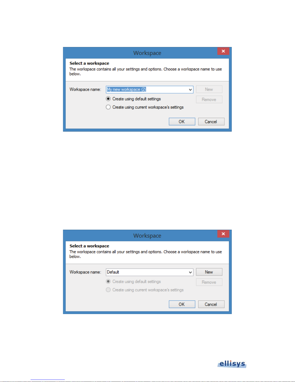
A new Workspace name appears:
User Guide
3. Accept the name provided by the application, or type in a new name in the Workspace name box. Select
Create using default settings to establish a new Workspace based on the default settings.
Or
Select Create using current workspace’s settings to establish the new workspace based on the current
settings.
4. Select OK.
To change from one Workspace to another:
1. Select File | Switch Workspace from the menu.
The
Workspace
2. Select the Workspace name drop-down arrow.
menu appears:
3. Select the desired Workspace name.
70 of 157 | Analyzer Workspaces and Layouts
Page 71
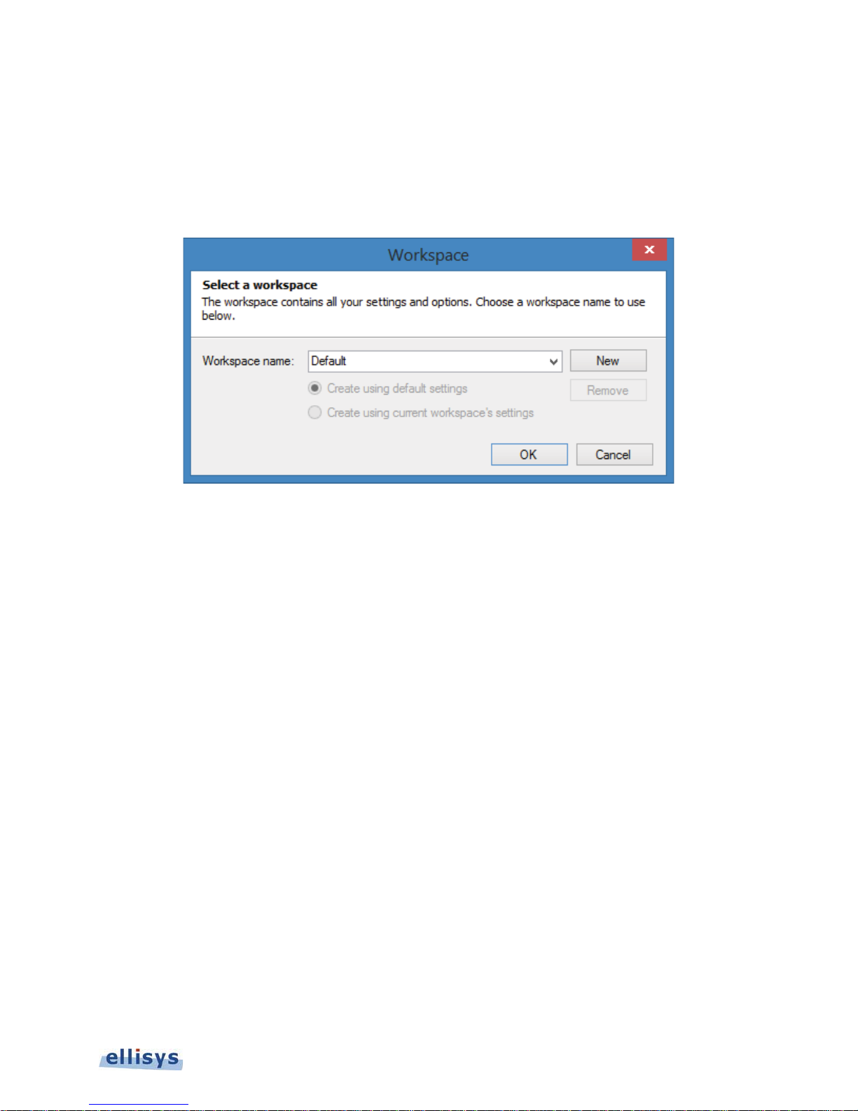
4. Click on OK.
To remove a Workspace:
1. Select File | Switch Workspace from the menu.
Workspace
The
2. Select the Workspace name drop-down arrow.
3. Select the desired Workspace name.
4. Click on Remove.
menu appears:
Ellisys USB Explorer 350
5. Click on OK.
To export Workspace settings to a file:
1. Select File | Import and Export Settings from the menu.
Analyzer Workspaces and Layouts | 71 of 157
Page 72
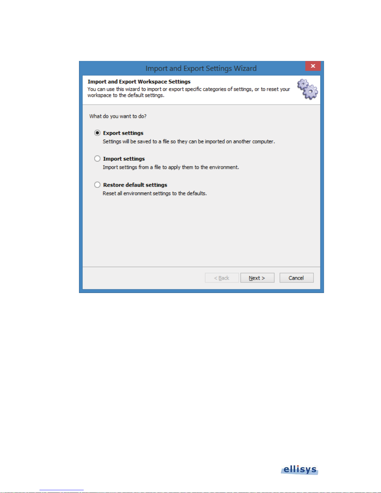
The
Import and Export Settings Wizard
User Guide
menu appears:
2. Select Export settings.
3. Click on Next.
72 of 157 | Analyzer Workspaces and Layouts
Page 73
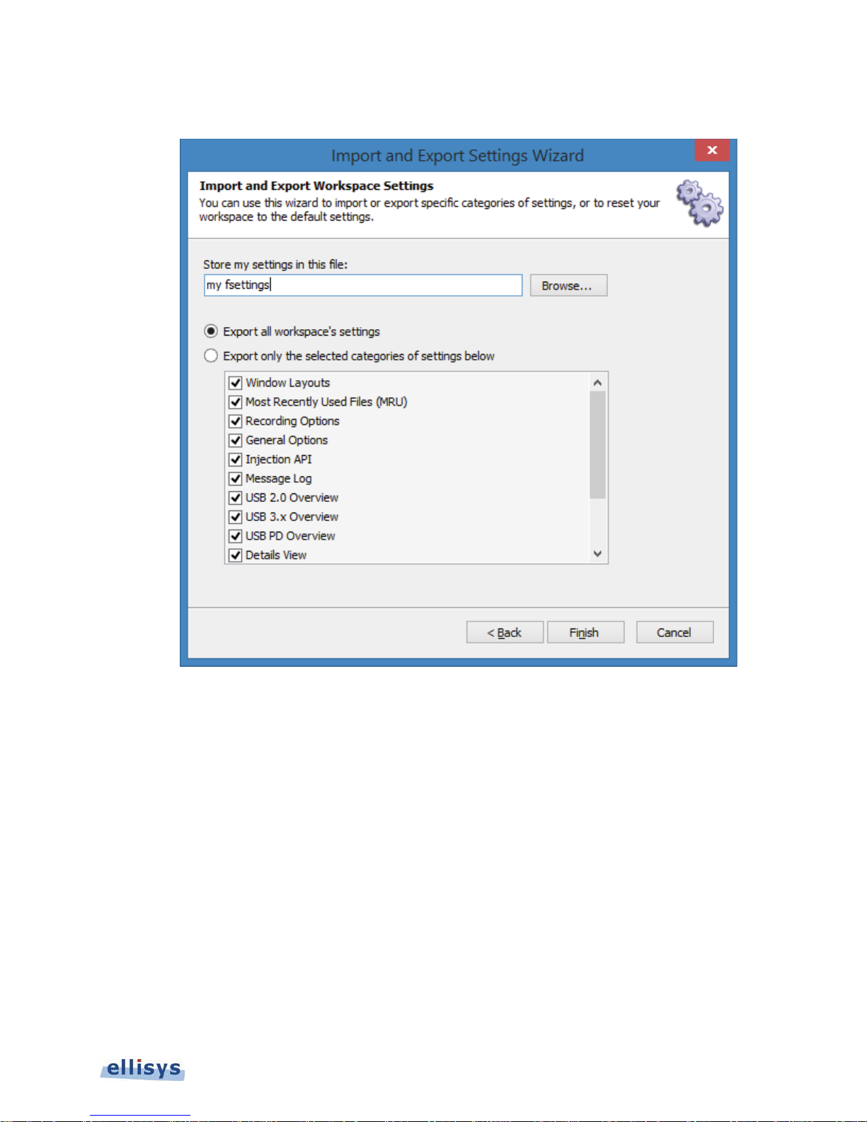
The
Settings Export
menu appears:
Ellisys USB Explorer 350
4. Select Export all workspace’s setting
Or
Select Export only the selected categories of settings below and check the desired categories.
5. Select Browse to specify a location to name and save the file.
6. Click on Finish.
To import a Workspace settings file:
1. Select File | Import and Export Settings from the menu.
Analyzer Workspaces and Layouts | 73 of 157
Page 74
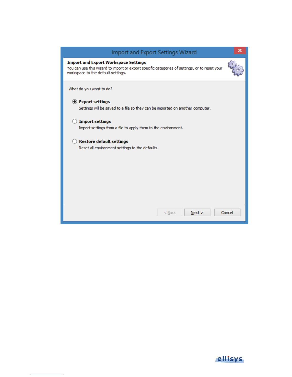
The
Import and Export Settings Wizard
User Guide
menu appears:
2. Select Import settings.
3. Click on Next.
74 of 157 | Analyzer Workspaces and Layouts
Page 75
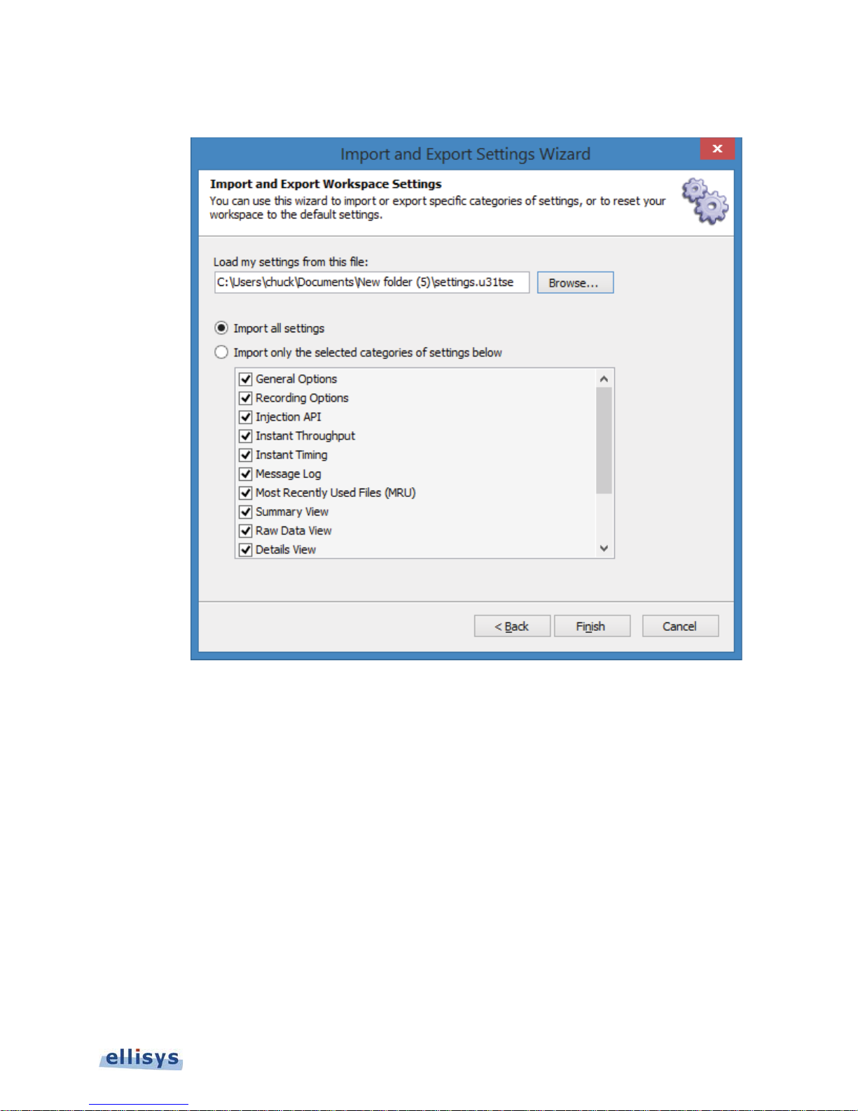
The
SettingsImport
menu appears:
Ellisys USB Explorer 350
4. Select Import all settings
Or
Select Import only the selected categories of settings below and check the desired categories.
5. Select Browse to specify a location to name and save the file.
6. Click on Finish.
To restore default Workspace settings:
1. Select File | Import and Export Settings from the menu.
Analyzer Workspaces and Layouts | 75 of 157
Page 76
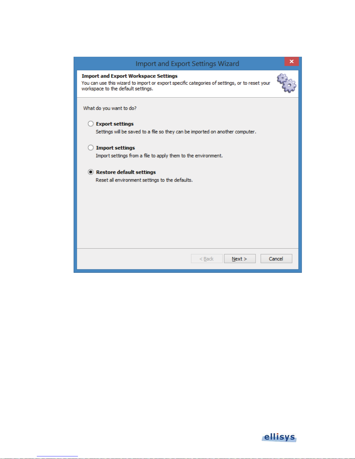
The
Import and Export Settings Wizard
User Guide
menu appears:
2. Select Restore default settings.
3. Click on Next.
76 of 157 | Analyzer Workspaces and Layouts
Page 77
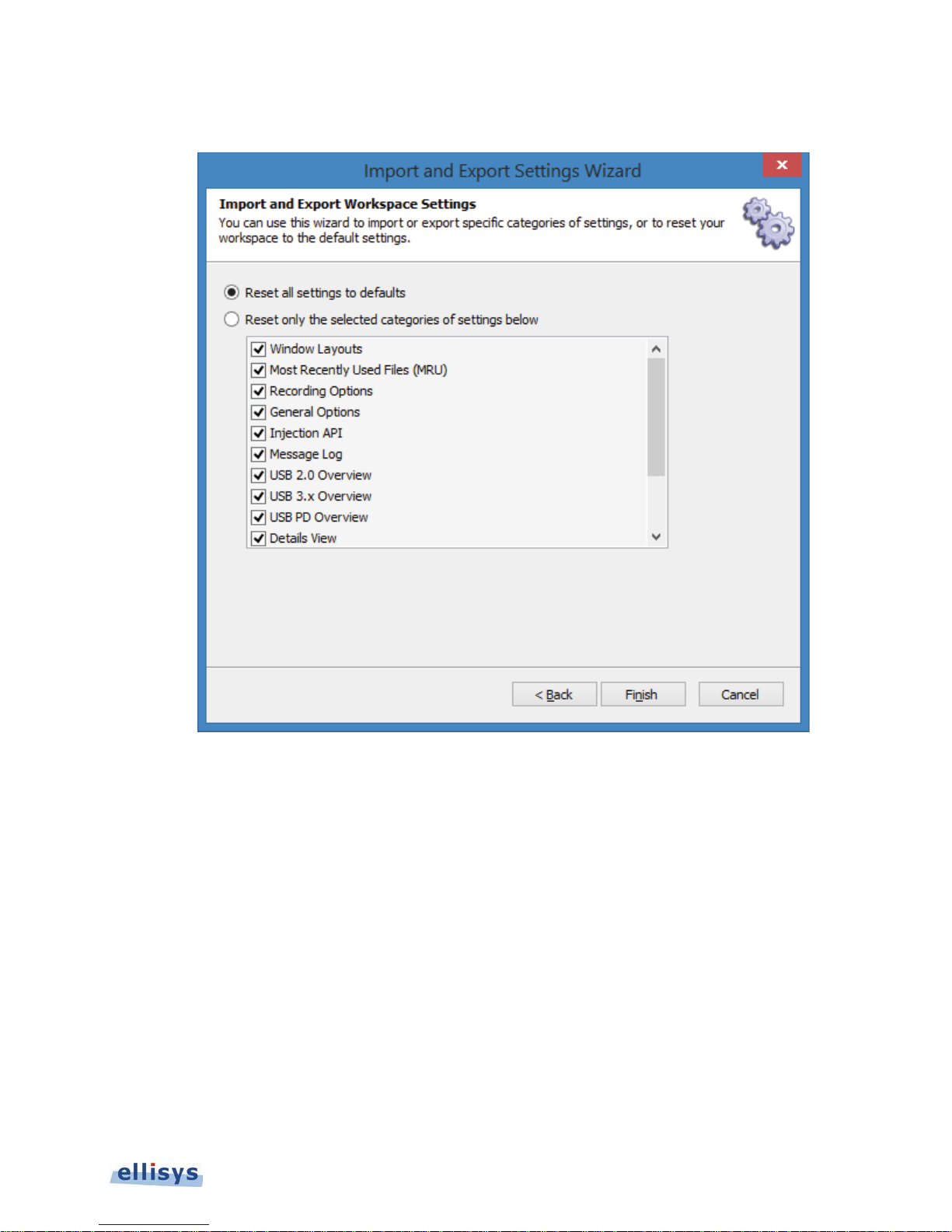
The reset default menu appears:
Ellisys USB Explorer 350
4. Select Reset all settings to defaults.
Or
Select Reset only the selected categories of setting below and check the desired categories.
5. Click on Finish.
8.2 Using Layouts
Layouts can be used to customize the size and position of the application’s various panes and windows. Layouts can
also be used to customize which panes and windows are displayed. On installation of the Analyzer application, a
default layout is provided, but users may add additional layouts as desired. Layouts are auto-saved, in that as
changes are made to the active layout, they are saved to that layout without any further action required by the user.
To create a new layout:
1. Select Layout | New Layout from the menu or use the Add… button on the main Tool Bar.
Analyzer Workspaces and Layouts | 77 of 157
Page 78
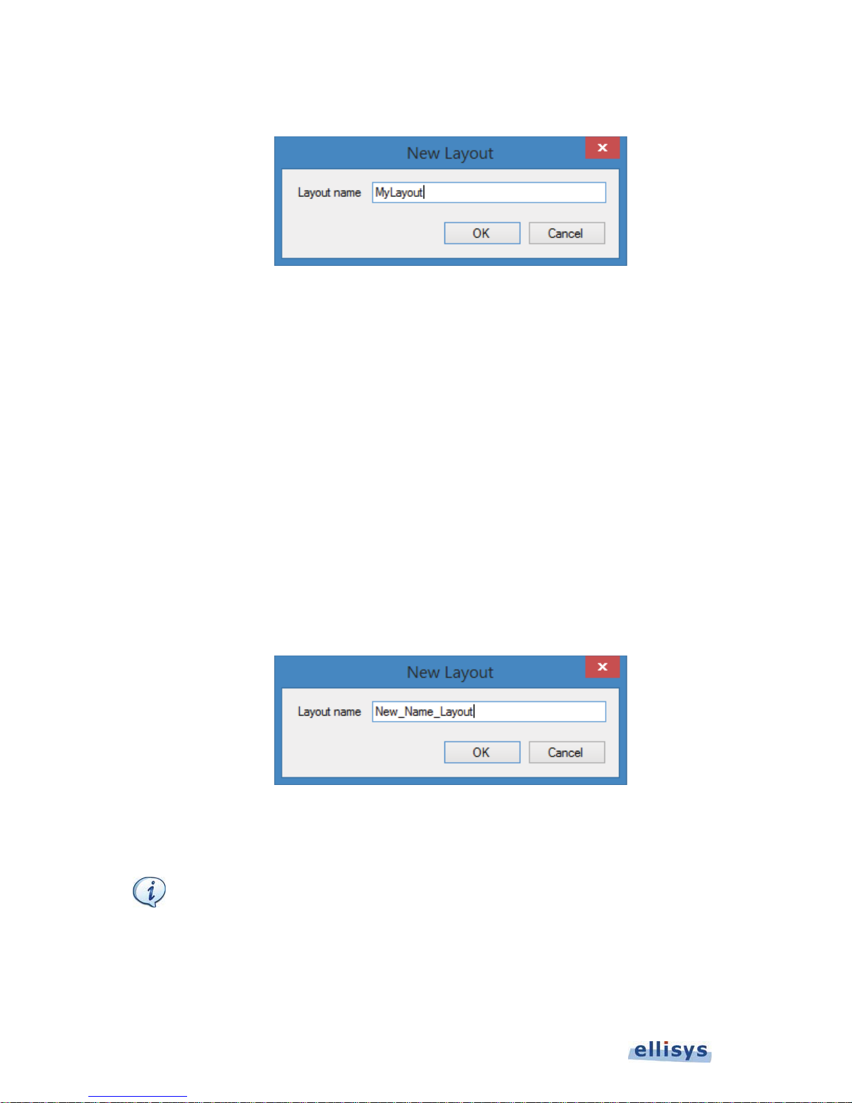
The
T
New Layout
dialog appears:
User Guide
2. Enter a name for the layout and click on OK.
The new layout is created and is now accessible in the View | Layout menu.
To reset a layout to factory default:
1. Select Layout | Reset Layout from the menu.
The layout is reset to the factory default.
To delete a layout:
1. Select Layout | Delete Layout from the menu.
The active layout is deleted and removed from the layouts listed in the View | Layout menu.
To rename a layout:
1. Select Layout | Rename Layout from the menu.
The
New Layout
2. Type the name desired in the dialog and click on OK.
The layout is renamed.
dialog appears:
he Default
Analyzer
layout cannot be renamed or deleted.
78 of 157 | Analyzer Workspaces and Layouts
Page 79
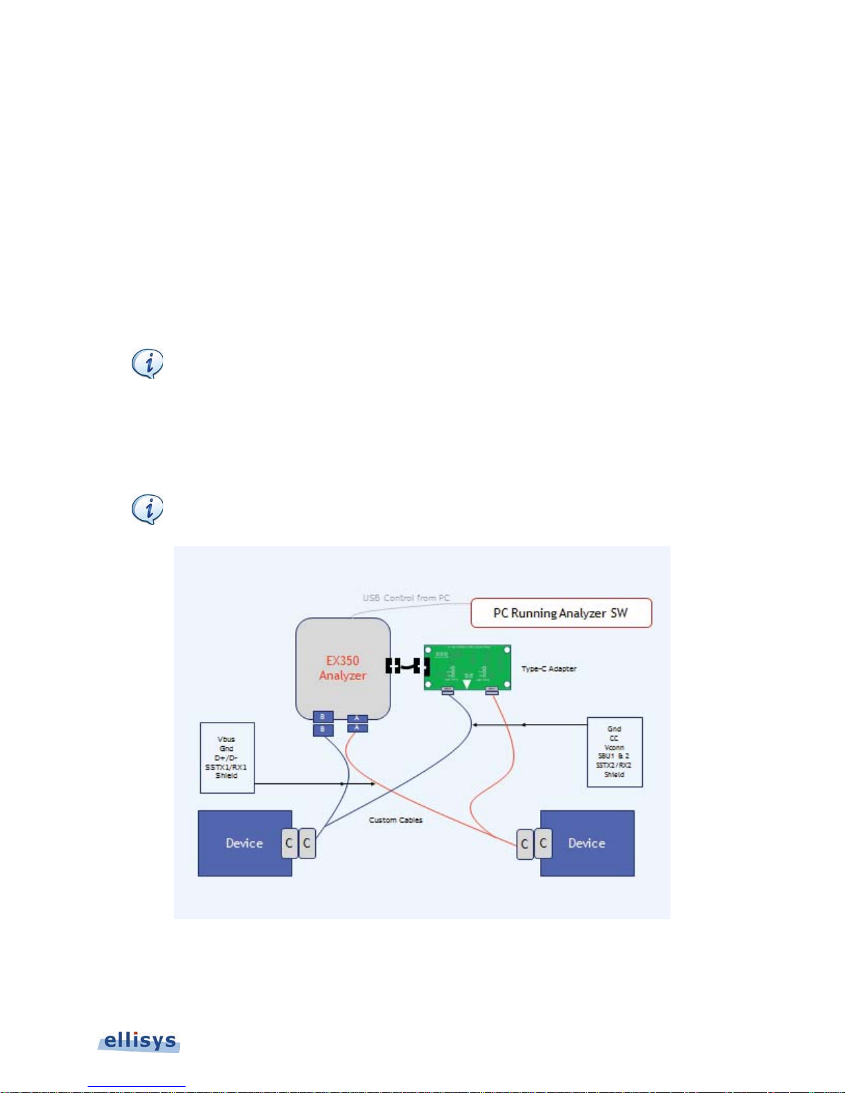
9. Analyzer – Setting Up
T
Various settings are available to control how bus traffic and events are captured, whether any traffic is filtered from
the Analyzer’s memory, when a capture should start and end, and various other settings that configure the Analyzer
to properly record traffic in accordance with the user’s preferences and expected bus characteristics.
9.1 Analyzer Hardware Setup – Type-C
The basic setup for taking a recording involves placing the Analyzer between communicating two ports, such as
between a device and a host or between a Provider and a Consumer, etc. This is shown below in Figure 33 Basic
Analyzer Setup.
he supplied 24VDC Power Supply is not shown below but is required.
The USB Explorer 350 is placed between two system components, such as a USB host and device, and is connected
over a USB 3.1 Gen 1 connection to a computer that hosts the Analyzer application. This USB connection is used to
program the Analyzer for the capture characteristics desired by the user, and to upload traffic to the Analyzer
application.
Note that the use of the word “Device” in the figure below is generic (these may be a USB host,
a USB peripheral, a Power Delivery Provider, a Power Delivery Consumer, etc.).
Ellisys USB Explorer 350
Figure 33 Basic Analyzer Setup
Analyzer – Setting Up | 79 of 157
Page 80
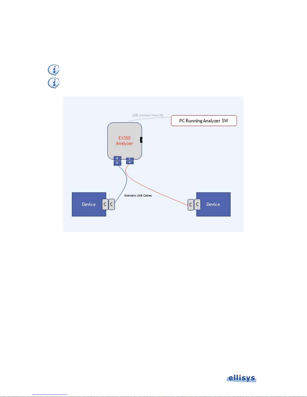
9.2 Analyzer Hardware Setup – USB Standard Cables
T
The Analyzer setup when using Standard USB cables is as shown below.
he supplied 24VDC Power Supply is not shown below but is required.
Note that the use of the word “Device” in the figure below is generic (these may be a USB host,
User Guide
a USB peripheral, a Power Delivery Provider, a Power Delivery Consumer, etc.).
Figure 34 Basic Analyzer Setup Using Standard USB Cables
80 of 157 | Analyzer – Setting Up
Page 81
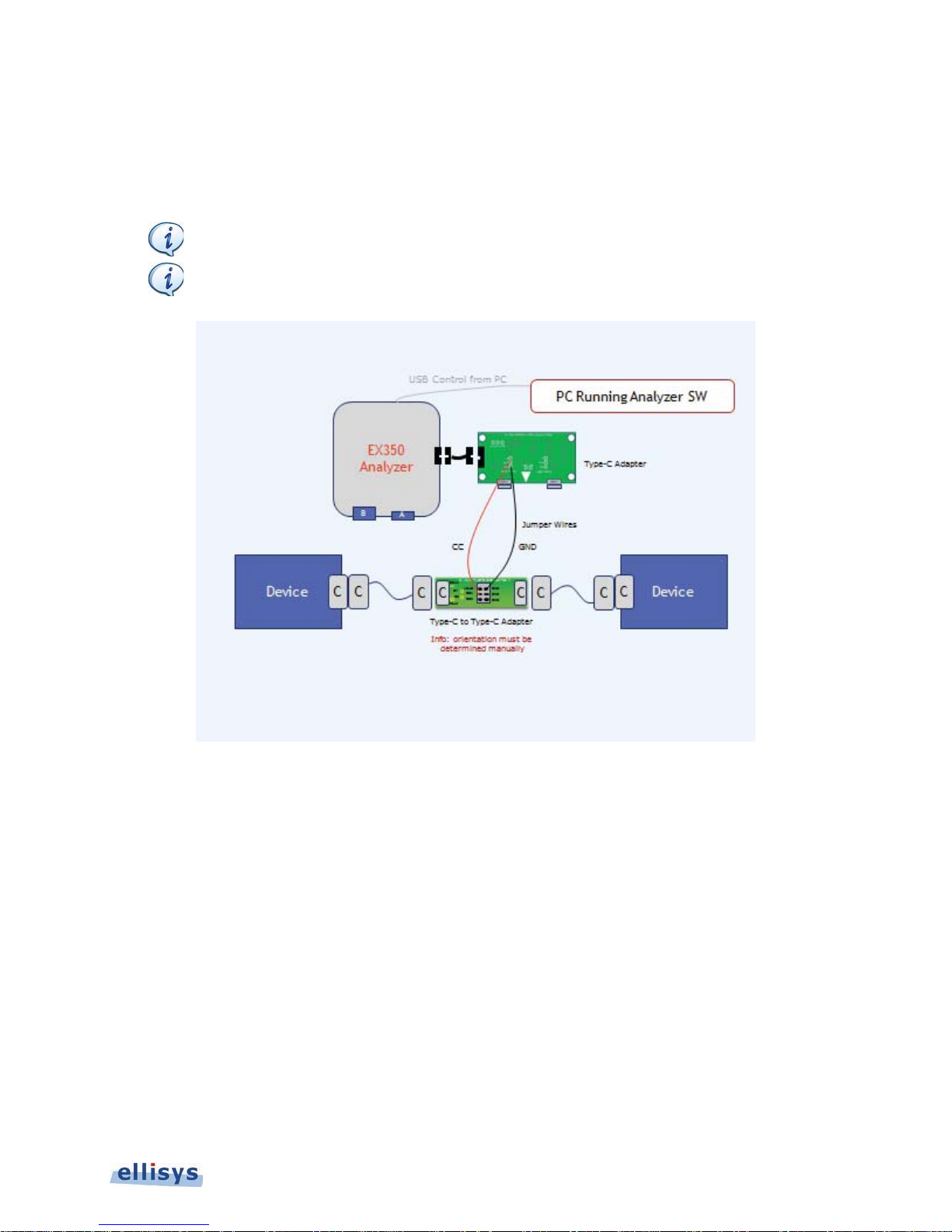
9.3 Analyzer Hardware Setup – Alternate Setup for CC Capture
T
Figure 35 Alternate Analyzer Setup for CC Capture, depicts a capture setup approach using the supplied Type-C-toType-C adapter and jumper wires to connect to the Configuration Channel (CC) wire and Ground.
he supplied 24VDC Power Supply is not shown below but is required.
Proper orientation is not guaranteed and may require the user to flip a Device’s Type-C plug to
ensure CC is connected to the Analyzer.
Ellisys USB Explorer 350
Figure 35 Alternate Analyzer Setup for CC Capture
Analyzer – Setting Up | 81 of 157
Page 82
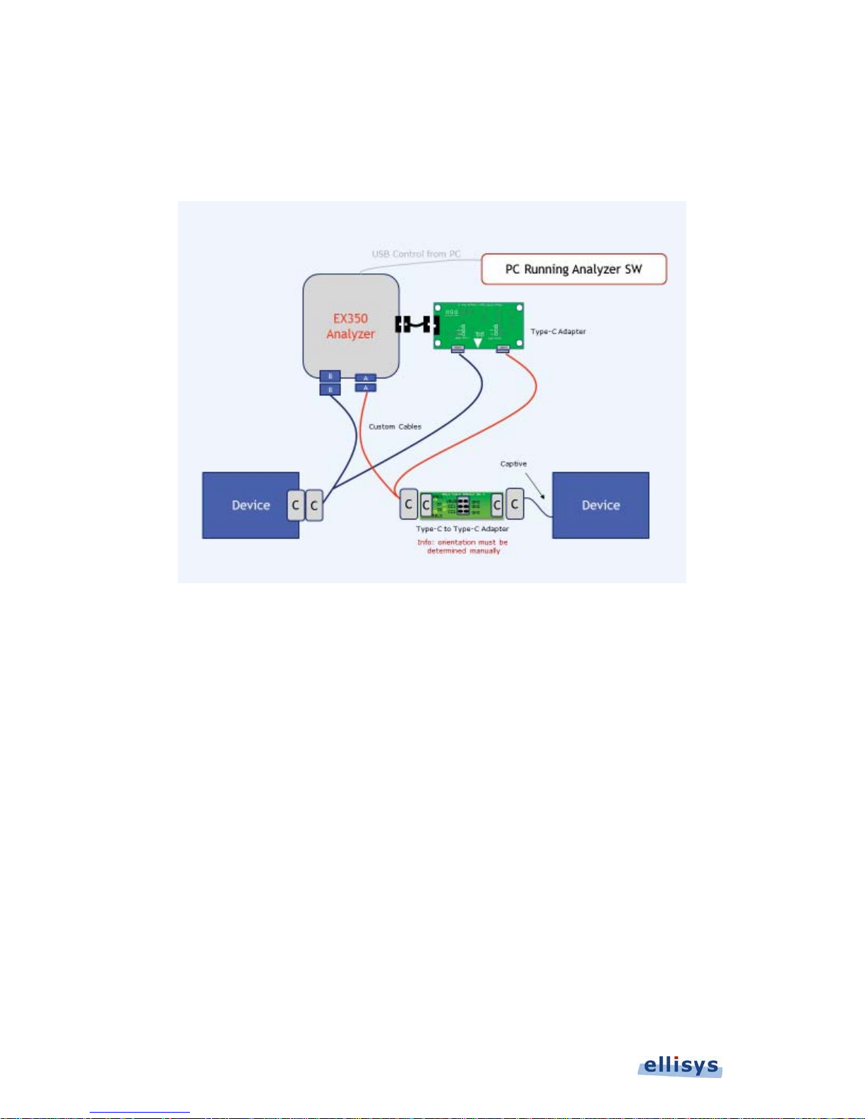
9.4 Analyzer Hardware Setup – Devices with Captive Cable
When analyzing a device that employs a captive cable, it is necessary to use the supplied Type-C-to-Type-C adapter
as shown in Figure 36 Analyzer Setup for Captive Cable, below.
User Guide
Figure 36 Analyzer Setup for Captive Cable
82 of 157 | Analyzer – Setting Up
Page 83
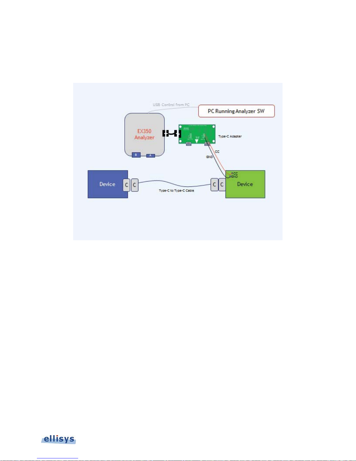
9.5 Analyzer Hardware Setup – Passive Tapping to Board
The Analyzer can be used to tap directly to a board, such as boards that are typically used during early development
stages. This setup is depicted below in Figure 37 Analyzer Setup to Tap Board Directly.
Ellisys USB Explorer 350
Figure 37 Analyzer Setup to Tap Board Directly
Analyzer – Setting Up | 83 of 157
Page 84
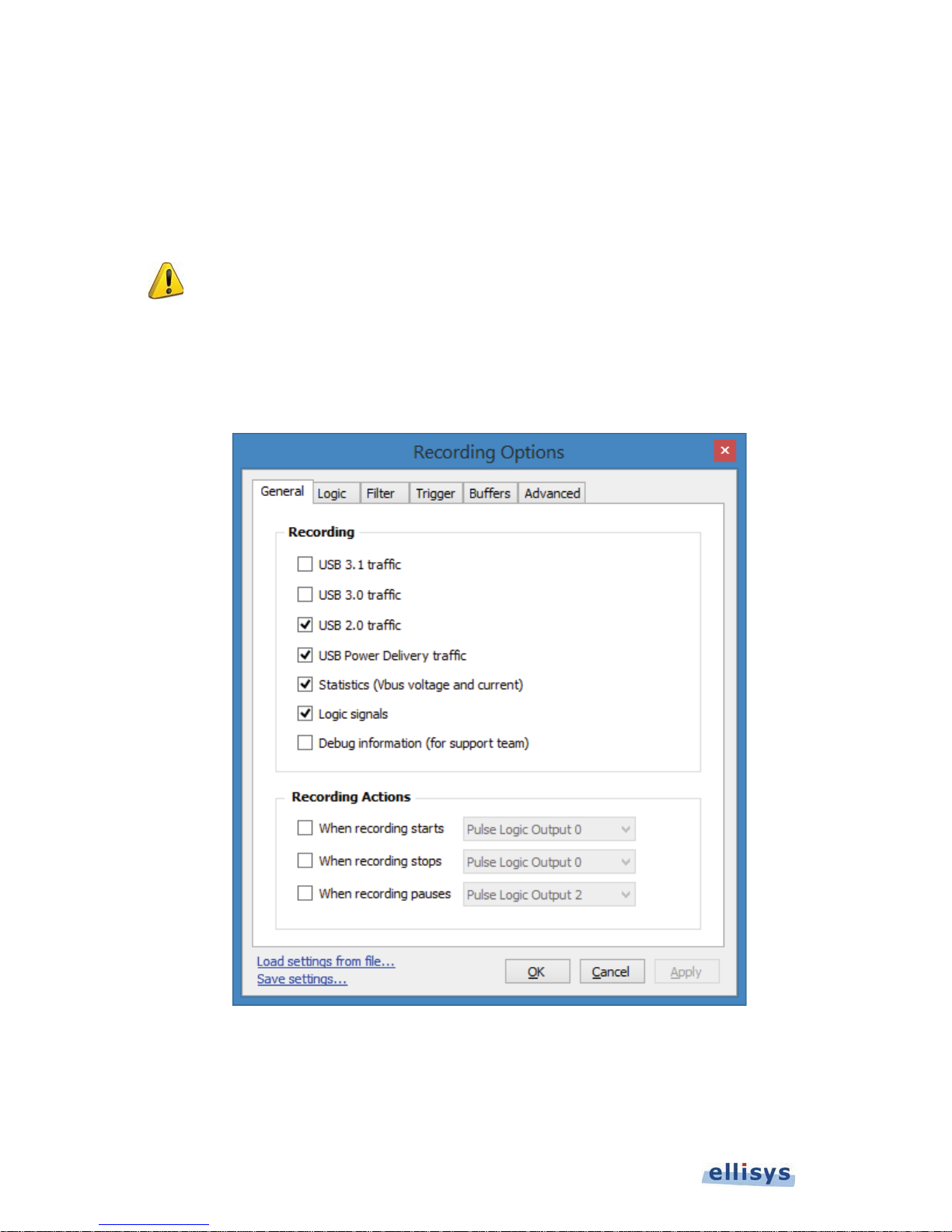
10. Managing Analyzer Recordings
10.1 Setting the Recording Options
The
Recording Options
menu settings control various characteristics of the Analyzer hardware during a recording.
User Guide
To access the recording options:
1. Select Record | Recording Options from the menu.
Recording Options
The
Options selected in the
data may reflect incorrect settings. Review these settings carefully before taking a capture.
menu appears:
Recording Options
menu are critical. Captures with errors or missing
84 of 157 | Managing Analyzer Recordings
Figure 38 Recording Options Menu
Page 85

The table below explains the recording options settings available under the General tab.
General Tab
Recording
USB 3.1 Traffic Enables the recording of USB 3.1 traffic.
USB 3.0 Traffic Enables the recording of USB 3.0 traffic.
USB 2.0 Traffic Enables the recording of USB 2.0 traffic.
USB Power Delivery Traffic Enables the recording of USB PD traffic.
Statistics Enables the recording of Vbus Voltage and Current.
Logic Enables the recording of logic signals.
Debug Enables capture of debug information. Use only when
requested to do so by Ellisys Support.
Recording Actions
When Recording Starts Specifies an action (pulse, toggle, or state change) on the EXT
TRIG connector when recording starts.
When Recording Ends Specifies an action (pulse, toggle, or state change) on the EXT
TRIG connector when recording ends.
Ellisys USB Explorer 350
When Recording Pauses Specifies an action (pulse, toggle, or state change) on the EXT
To set Logic capture options, select the Logic tab:
TRIG connector when recording is paused.
Managing Analyzer Recordings | 85 of 157
Page 86
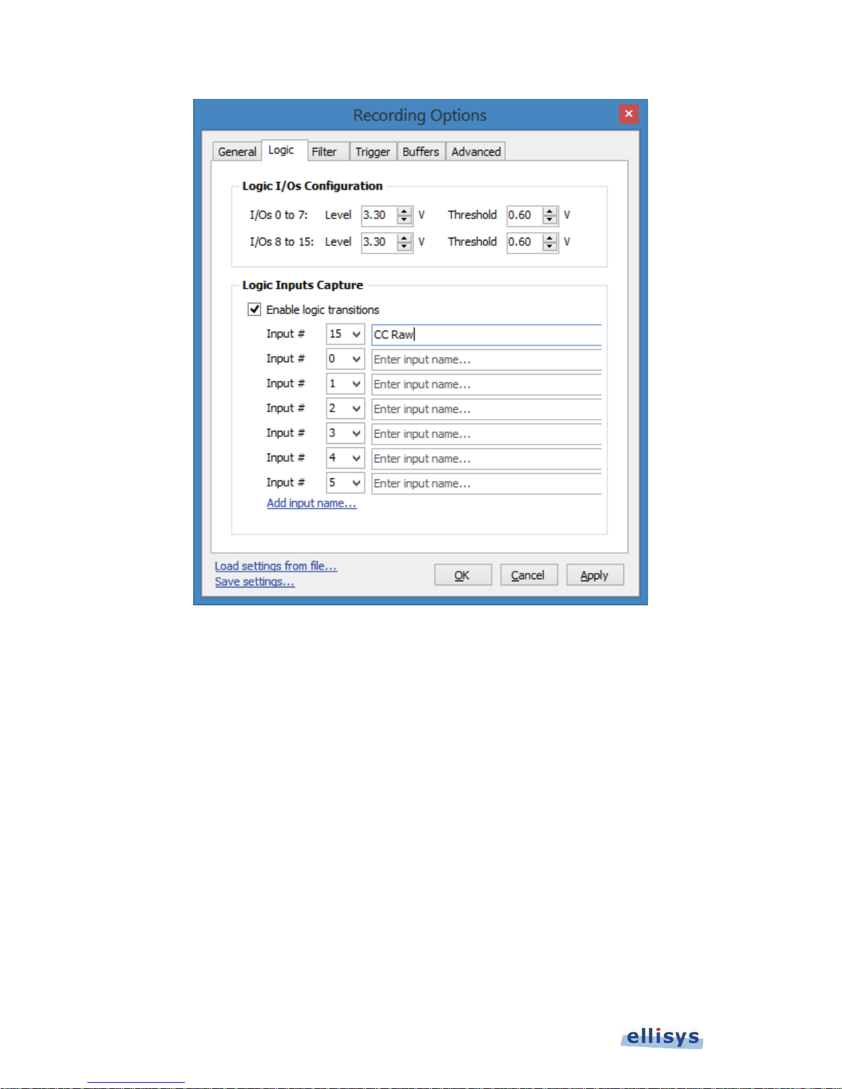
User Guide
86 of 157 | Managing Analyzer Recordings
Page 87
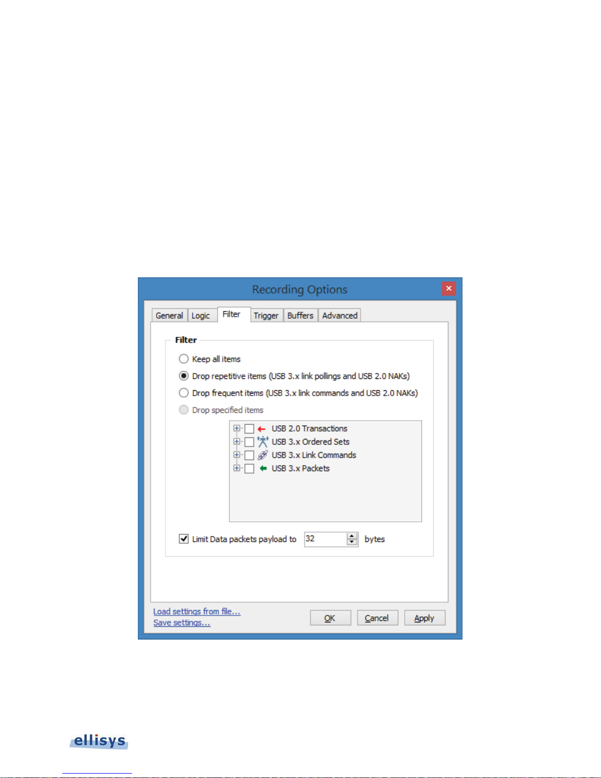
Logic Tab
Logic I/Os Configuration
I/Os 0 to 7 Provides user selection for Level and Threshold.
I/Os 8 to 15 Provides user selection for Level and Threshold.
Logic Inputs Capture
Enable Logic Transitions When checked, the user may define logic inputs for capture.
Input Number Allow the user to specify and name up to 15 inputs.
When Recording Pauses Specifies an action (pulse, toggle, or state change) on the EXT
To set hardware filter options, select the Filter tab:
TRIG connector when recording is paused.
Ellisys USB Explorer 350
Managing Analyzer Recordings | 87 of 157
Page 88
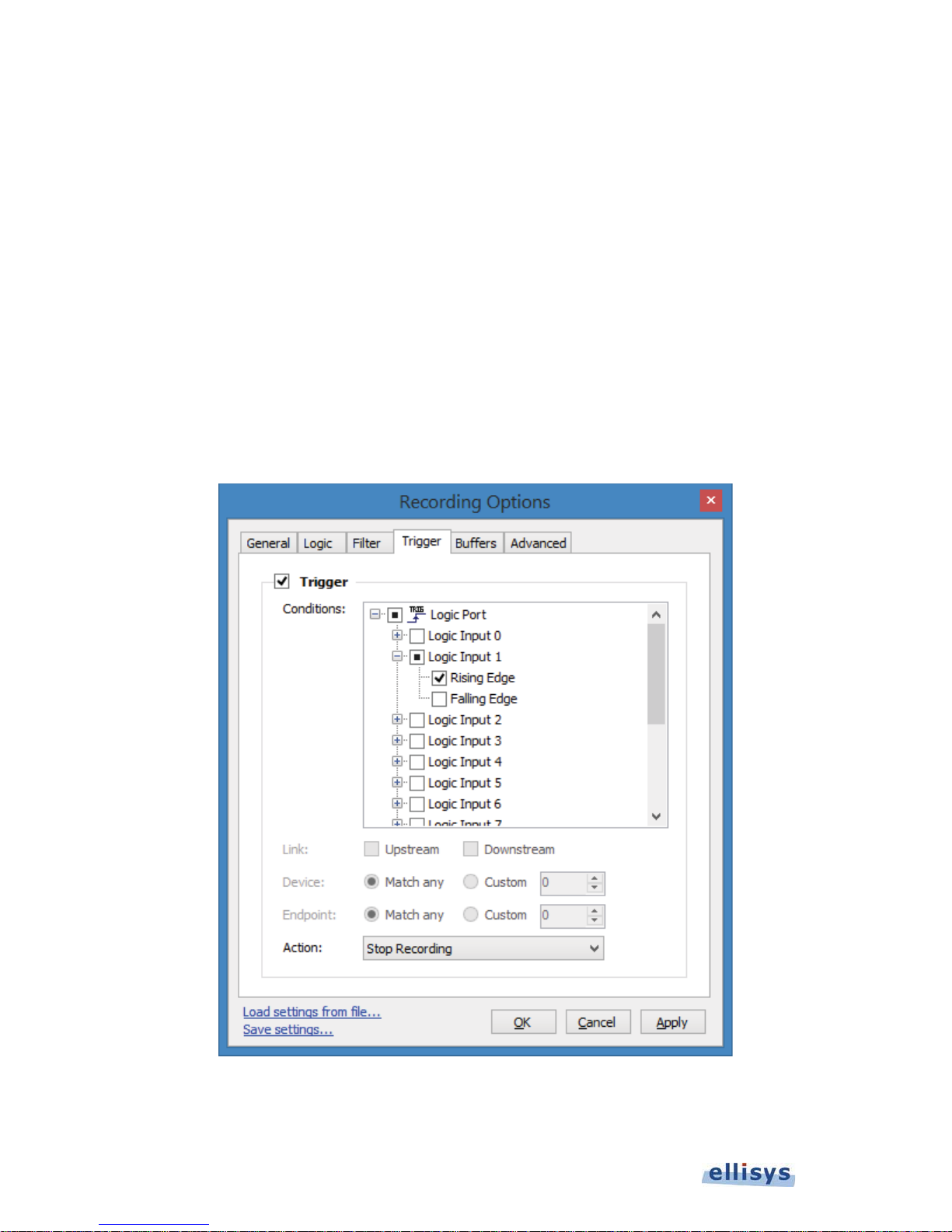
The table below explains the settings available under the Filter tab:
Filter Tab
Basic Filter
Keep all items All traffic is captured to the Analyzer’s memory.
Drop repetitive items USB 3.1 Link Polling commands (LDN, LUP) and USB 2.0 NAK
User Guide
Drop frequent items USB 3.1 Link commands and USB 2.0 NAK transactions are
Drop specified items Enables a list of USB 3.1 ordered sets, link commands, and
Limit Payload Truncates payload to the amount of bytes specified.
To set trigger options, select the Trigger tab:
transactions are excluded from capture.
excluded from capture.
packets that can be selected for exclusion from the capture.
88 of 157 | Managing Analyzer Recordings
Page 89
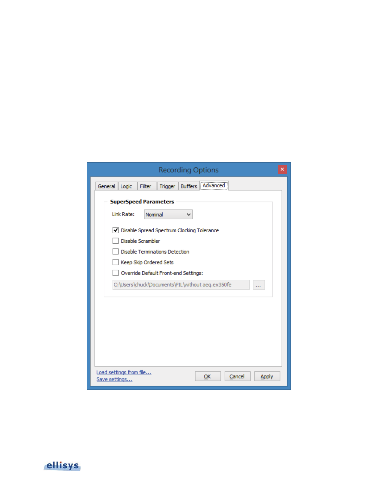
The table below explains the settings available under the Trigger tab:
Trigger Tab
Conditions Enables selection of various conditions that can be used to trigger the
Analyzer recording.
Link Applies the selected trigger condition(s) to the upstream or downstream link.
Device Applies the selected trigger condition(s ) to selected device address.
Endpoint Applies the selected trigger conditions(s) to the selected endpoint.
Action Defines an action on the logic connector (pulse, toggle, or state change).
To set advanced options, select the Advanced tab:
Ellisys USB Explorer 350
Managing Analyzer Recordings | 89 of 157
Page 90
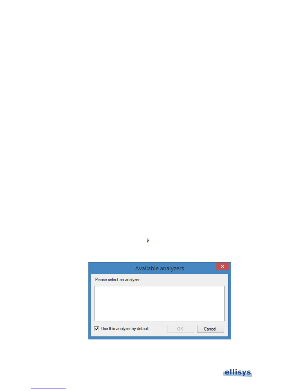
The table below explains the settings available under the Advanced tab:
Advanced Tab
SuperSpeed Parameters
Link Rate Specifies the link operating speed. Defaults to auto-detect nominal.
User may also specify a division by two.
User Guide
Disable Spread Spectrum
Clocking Tolerance
Disable Scrambler When checked, traffic captured by the Analyzer is not descrambled.
Disable Terminations
Detection
Keep Skip Ordered Sets When checked, the Skip ordered sets are kept. Please be aware that
Override Default Front-End
Settings
When checked, configures the Analyzer to record traffic that utilizes
spread spectrum clocking.
When checked, the receive lines on the Analyzer’s upstream and
downstream ports will always present receiver terminations to the
attached device’s transmit lines. When unchecked, the Analyzer
presents receiver terminations only when both upstream and
downstream devices are attached to the Analyzer’s front panel.
this option will generate a huge quantity of items.
10.2 Selecting an Analyzer
It is possible that multiple units will be attached to a single PC hosting the Analyzer desired for recording.
To select an Analyzer:
1. Select Record | Select an Analyzer from the menu.
Or
Select the drop-down arrow located on the Record button located on the toolbar.
Available Analyzers
The
2. Select the desired Analyzer.
90 of 157 | Managing Analyzer Recordings
dialog appears:
Page 91

3. Click on OK.
If a recording is initiated without having first selected an Analyzer, the
will pop up to request the user to select an Analyzer. Selecting the default checkbox in this
dialog will conveniently force the automatic selection of the specified Analyzer on each new
recording.
Available Analyzers
dialog
10.3 Initiating a Recording
A recording can be initiated from the toolbar, keyboard, or the menu.
To initiate a recording:
1. Click on Record
Or
Select Record | Start Recording (CTRL+R) from the menu.
Recording is initiated according to settings in the Record | Recording Options menu.
on the toolbar.
10.4 Stopping a Recording
A recording can be manually stopped from the toolbar, keyboard, or the menu. Recording may also stop
automatically based on settings made in the Recording Options | Trigger menu.
Ellisys USB Explorer 350
To stop a recording:
1. Click on Stop
Or
Select Record | Stop Recording (CTRL+SHFT+R) from the menu.
The recording is stopped. Traffic remaining in the Analyzer’s memory is uploaded to the PC hosting the Analyzer
application.
on the toolbar.
10.5 Restarting a Recording
A recording in progress can be restarted from the toolbar or from the Record menu. When restarting a recording, a
dialog will give the user the option to save or discard traffic presently captured in the Analyzer’s memory.
To restart a recording:
1. Click on Restart
Or
Select Record | Restart Recording from the menu.
The capture in progress is halted, traffic captured is discarded, and a new recording is initiated.
on the toolbar.
Managing Analyzer Recordings | 91 of 157
Page 92
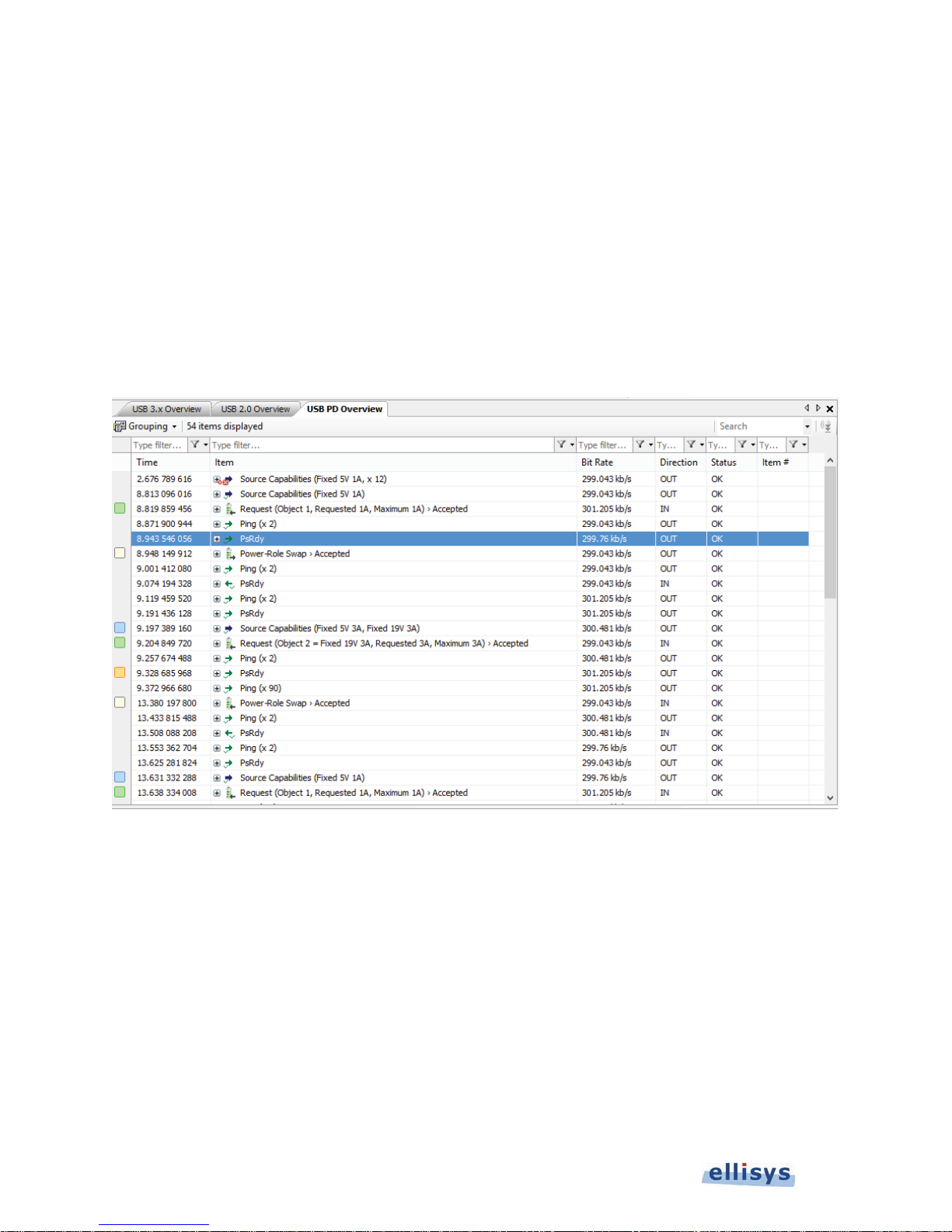
11. Analyzer Overview Windows
Overview
An
Overview
features, filter features, LTSSM state change indicators, standard descriptor and class-specific information.
Overviews are provided for USB 3.x, USB Power Delivery, and USB 2.0.
User Guide
To select an Overview:
is the primary viewer window, providing a user-configurable display of all bus events and traffic, search
1. Select View | Overviews from the View menu, then select the desired
2. The selected
Overview
is displayed:
Overview
.
11.1 Configuring the Display
The columns and displayed in an
Color assignments are also available.
To add a column to an
1. Right-click on any column header (e.g., Item, Time, etc.).
2. Select the desired column to be added from the default list.
Or
Select the desired event in the
3. Go to the
92 of 157 | Analyzer Overview Windows
Details View
O
(View | Details)
Overview
:
Overview
, including their position and width, are fully configurable by the user.
to highlight the event.
Page 93

4. Left-click and drag the icon at the left of the desired field in the
Overview
Overview
Or
Click on the
The new column is added and populated with the relevant data.
.
Display this field in the Overview
button in the Details toolbar.
Details View
to the column header in the
To move a column in an
1. Left-click the column header atop the desired column and drag left or right as desired.
The column is re-positioned.
To resize a column:
1. Position the mouse pointer at the vertical line border at the left or right of the desired column.
2. When the mouse pointer changes to a resize indicator, left-click and drag to the desired size.
The column is resized.
To hide a column:
1. Right click on the desired column header.
2. Select Hide Column.
Or
Right-click on any column header.
3. Select Columns.
O
:
Ellisys USB Explorer 350
4. Deselect the desired column from the list.
The column is hidden.
To add color-coding:
1. Right-click in the desired
Overview
and select Coloring | Add Color.
Analyzer Overview Windows | 93 of 157
Page 94
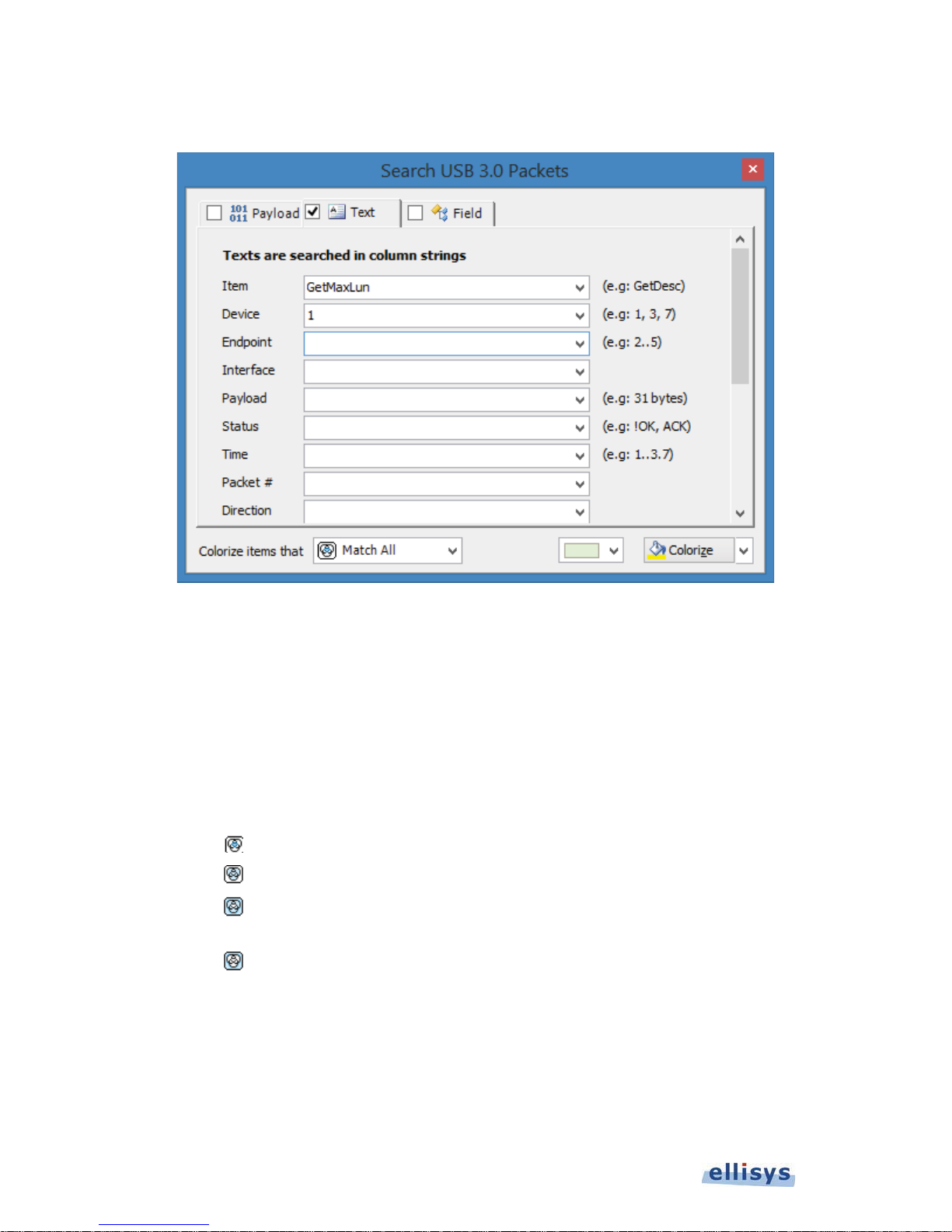
The
Colorize
dialog appears:
User Guide
To colorize events by payload content:
1. Select the Payload tab.
2. Enter Data to search for and/or a payload Length range.
3. Select Data Type as needed.
4. Select Search in Packets or Search in Transactions to highlight matching packets or transactions.
5. Select the desired match type in the Colorize items that drop-down menu.
Match Any – Finds items that match any of the criteria.
Don’t Match All – Finds items that do not match all of the selected cr iteria (opposite of Match
6. Select the desired color and click on Colorize.
Match All – Finds items that match all selected criteria.
All).
Don’t Match Any – Finds items that do not match any of the selected criteria (opposite of
Match Any).
Events matching are colorized in the
94 of 157 | Analyzer Overview Windows
Overview
.
Page 95
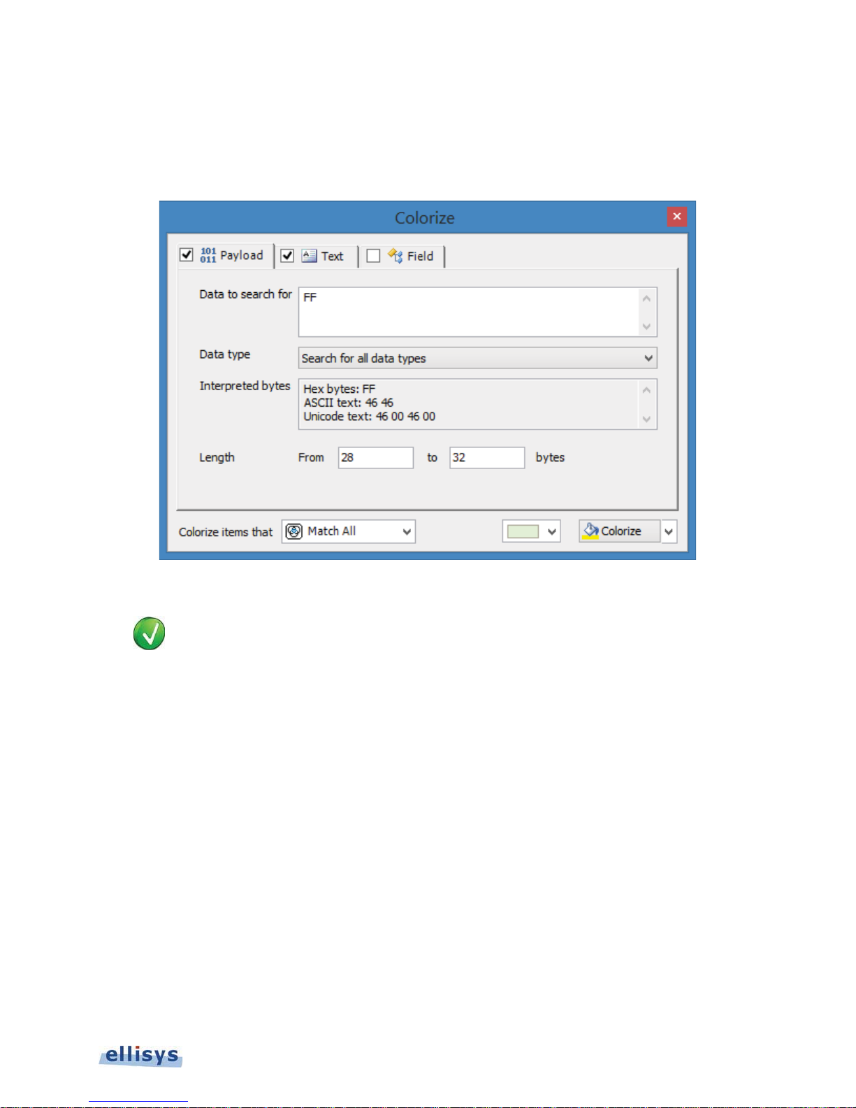
To colorize events by text string:
T
1. Select the Text tab.
The Text tab appears:
Ellisys USB Explorer 350
2. Use the one or more text string drop-down menus provided to characterize the color search.
ext entered into the various boxes by selecting an item in the drop-down menus can be edited,
or text may simply be entered directly into the boxes without selecting the drop-down menus.
Use commas to separate OR items on any line. Use of the ! (NOT) symbol will exclude a text
string from the search.
3. Select the desired color and click on Colorize.
Matching events are colorized in the applicable
To colorize events by field value:
1. Select the Field tab.
Overview
.
Analyzer Overview Windows | 95 of 157
Page 96
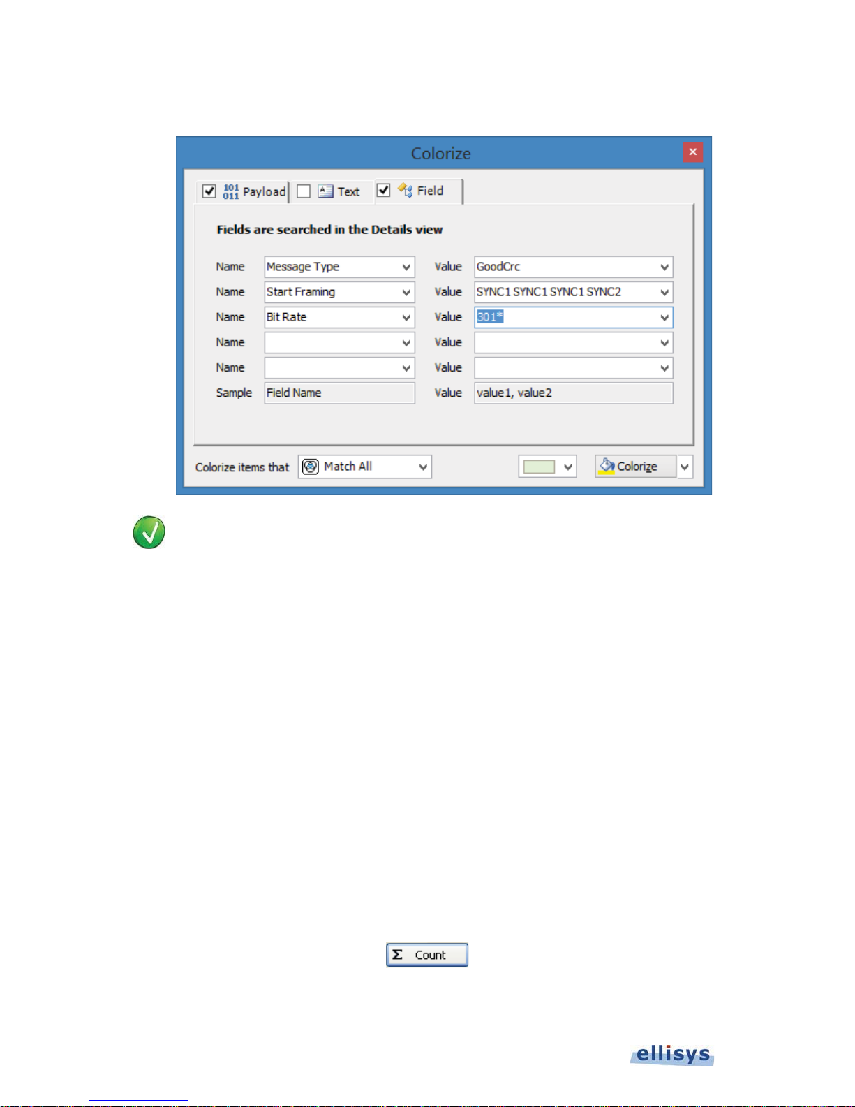
The Field tab appears:
V
User Guide
alues in the Name boxes are synchronized to the selected event in the active Overview, which
is synchronized to the Details view. The Value boxes reflect data elements displayed in the
Details View. Users may type strings (values, wildcards, or ranges) directly into the Value boxes.
2. Select one or more items from the Name boxes.
3. Select corresponding items from the Value boxes.
4. Select the desired match type in the Colorize items that drop-down menu.
5. Select the desired color and click on Colorize.
Events matching are colorized in the applicable
To display a count of matching criteria:
1. Define the search/colorize criteria from the Payload, Text, and/or Field tabs.
2. Select the drop-down arrow at the bottom-right of the Colorize dialog.
3. Select Count.
The Colorize button changes to a Count button:
Overview
.
4. Click on the Count button.
96 of 157 | Analyzer Overview Windows
Page 97
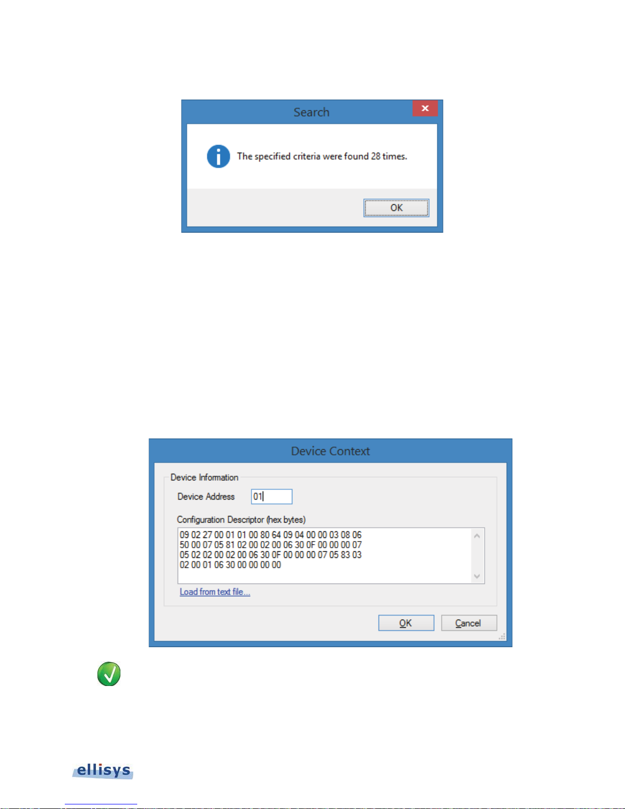
A count of items matching the criteria is displayed:
T
To add a Device Profile:
1. Right-click in the
2. Select Add Device Profile.
Device Context
The
3. Enter the address desired in the Device Address box.
4. Type, or paste a configuration descriptor using hex bytes into the Configuration Descriptor box as shown
below.
USB 3.1 or USB 2.0 Overview
dialog appears:
.
Ellisys USB Explorer 350
o copy a configuration descriptor from another trace file, open that trace file, select the
GetDescriptor (Configuration) transfer, and use the Raw Data dialog to copy the data for pasting
into the Device Context dialog.
5. Click on OK.
Analyzer Overview Windows | 97 of 157
Page 98

The capture presently displayed is updated with the new device profile.
11.2 Applying Display Filters
Various display filter options are available in the
the Instant Filter boxes atop the columns) as well as a set of categorized filters or other protocol-specific filters
depending on the Overview selected, located at the top-left of the applicable
Overviews
. These include Instant Filters (enacted as text strings in
Overview
.
User Guide
Instant Filters provide a quick and simple way to remove information from the
entered in the Instant Filter boxes atop each column. Instant Filters are comprised of a sequence of character chains
separated by commas. Instant Filters are not case-sensitive.
Use of display filters can speed the process of uploading captured traffic to the PC. Filtering
commonly occurring items that may not be required for the analysis task at hand, such as LCRD,
LGOOD, or Isochronous Timestamp Packets can be helpful.
Instant Filters Syntax
The syntax of Instant Filters is as shown below:
filters = [!]filter[,filter,…]
filter = string or wildcard range
wildcard = string containing * or ? characters
range = min..max
Wildcards can be used to perform advanced filtering operations. Use an interrogation point '?' to match to match any
character, or an asterisk '*' to match any suite of characters. An asterisk is always implied at the end of any search
string. A few examples:
Overview
using a simple syntax
")( will match any line that starts with and end with )(.
KHH will match any line that contains the word KHH.
( will match any line that starts with an ( and contains an .
LHK will match any line that contains LHK.
Filters also accept advanced criteria. For example, type in the time column to keep only events that
occur between 0 and 100 milliseconds.
Several criteria can be combined with a logical OR operation using a comma. For example, typing in the
device column will keep events having devices addresses beginning with 2 or 4.
A criteria can be inverted by using an exclamation point '!' as the first character in the filter. In this case, all events
that would have been included are now excluded, and vice versa.
To apply an Instant Filter:
1. Select an Instant Filter from one of the columns in the desired
Filter
2. Type the desired filter in the
98 of 157 | Analyzer Overview Windows
field.
Overview
.
Page 99
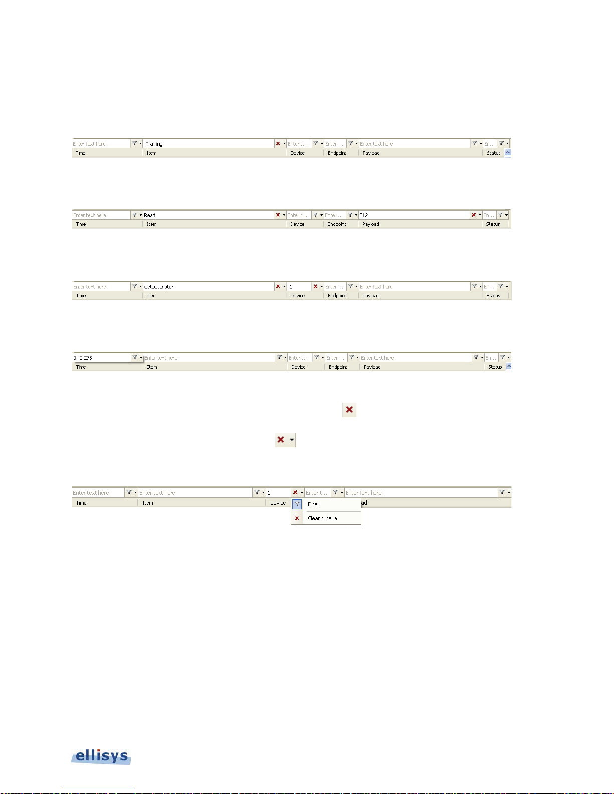
Examples
The example below will remove all items in the
training sequence ordered sets.
The example below will remove all items from the
word 5LHK returning payloads of bytes.
The example below will remove all items from the
address 1.
The example below will remove all items except those ite ms taking place between timestamps located at 0 and 275
milliseconds.
To remove a filter:
Overview
Overview
Overview
that begin with the string “7HPPN,” typically all
except events in the Items column beginning with the
except GetDescriptor requests to all addresses, except
Ellisys USB Explorer 350
1. Click on the red cross adjacent to the filter desired for removal .
Or
Click on the down arrow next to the red cross
A menu appears:
2. Click on Clear Criteria.
The selected filter is removed and the display updates.
Categorized Display Filters
A selection of categorized display filters is available in the
located at the top-left of the
To enable or disable a categorized filter:
1. Select the arrow adjacent to the View button at the top-left of the
USB 3.1 Overview.
.
USB 3.1 O verview
by selecting the View drop-down button
USB 3.1 Overview
.
Analyzer Overview Windows | 99 of 157
Page 100
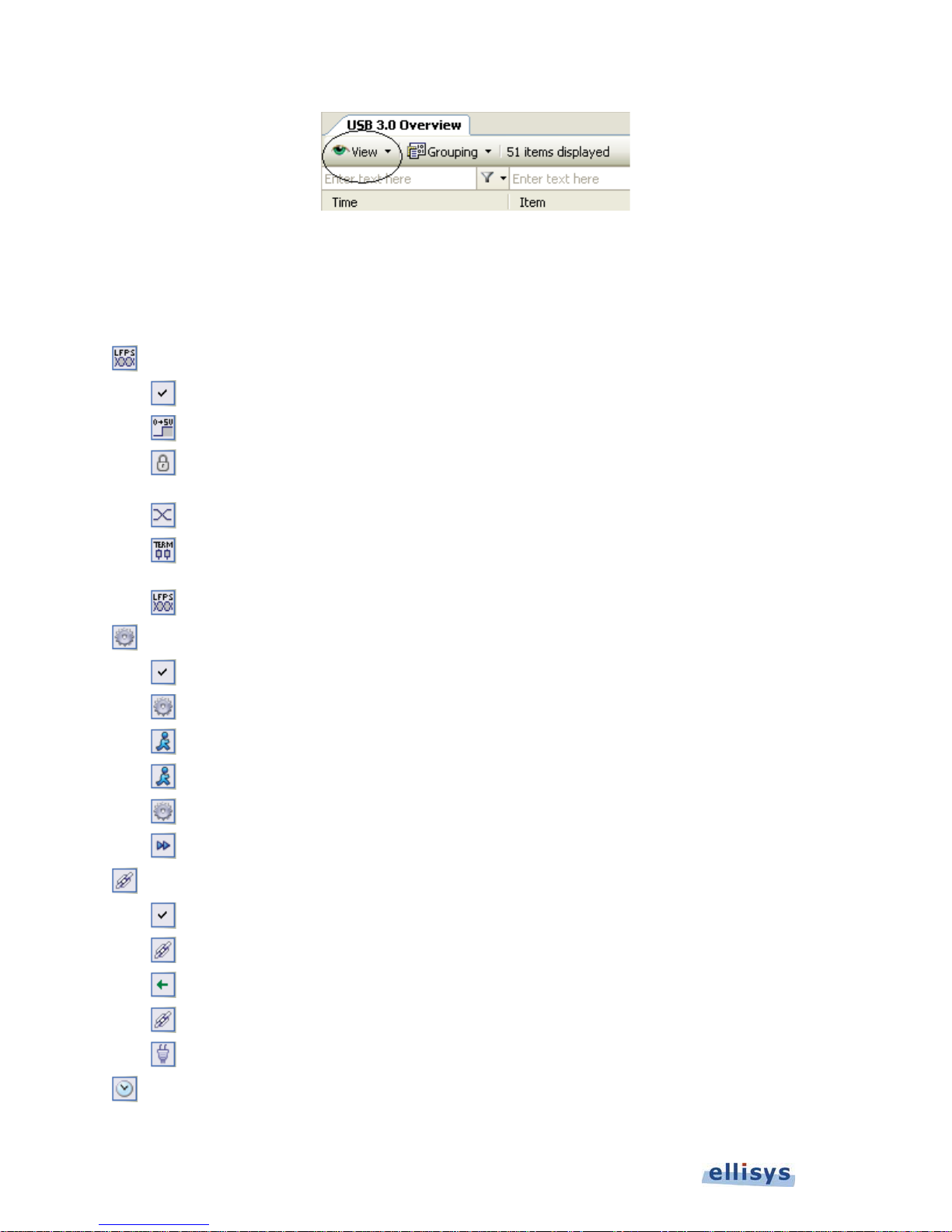
2. Select or deselect the desired filter as needed.
User Guide
USB 3.1 Overview
The
The table below describes the categorized filters:
Bus States
Show Bus States Shows/hides all bus states.
Show Power Changes Shows/hides all bus power changes (Power ON/OFF).
Show Receiver Lock Changes
Show Lane Polarity Changes Shows/hides changes in lane polarity.
Show Rx Termination Changes
Show LFPS Shows/hides LFPS events.
Ordered Sets
Show Ordered Sets Shows/hides all ordered sets.
Show Training Sequence Equalization Shows/hides TSEQ ordered sets.
updates with the selected setting.
Shows/hides changes in the Analyzer’s receiver lock
statuses.
Shows/hides changes in the Analyzer’s detection of
receiver terminations on the attached devices.
Show Training Sequence 1 (TS1) Shows/hides TS1 ordered sets.
Show Training Sequence 2 (TS2) Shows/hides TS2 ordered sets.
Show BERT Ordered Sets Shows/hides BERT ordered sets.
Show Skip Ordered Sets Shows/hides SKP ordered sets.
Show Link Commands
Show Link Commands Shows/hides all link commands.
Show Link Pollings Shows/hides link pollings (LDN/LUP).
Show Link Handshakes Shows/hides link handshakes.
Show Link Credits Shows/hides link credits.
Show Link Power Management Shows/hides link power management link commands.
Show Isochronous Timestamps Shows/hides isochronous timestamp transactions.
100 of 157 | Analyzer Overview Windows
 Loading...