

Page 1
USB Explorer 280
Examiner Compliance Test Suite
User Manual
Version 1.03
January 18, 2013
Page 2

2 of 124
Examiner User Guide
Copyright, Confidentiality and Disclaimer Statements
While the information in this publication is believed to be accurate, Ellisys makes no warranty of
any kind to this material including, but not limited to, the implied warranties of merchantability
and fitness for a particular purpose. Ellisys shall not be liable for any errors contained herein, or
for incidental or consequential damages in connection with the furnishing, performance or use
of this material.
No part of this publication may be reproduced, stored in a retrieval system or transmitted, in
any form or by any means, photocopying, recording or otherwise, without prior written consent
of Ellisys. No third party intellectual property right liability is assumed with respect to the use of
the information contained herein. Ellisys assumes no responsibility for errors or omissions
contained in this book. This publication and features described herein are subject to change
without notice.
Copyright (C) Ellisys 2011. All rights reserved.
All products or services mentioned in this manual are covered by trademarks, service marks, or
product names as designat ed by the companies who market those produ c ts .
This manual is populated throughout with screens captured from a specific version of Ellisys
Protocol Analyzer software. All information contained in the screens are samples, and serve as
instructional pu r p os es only.
Document Revi si o n Hist or y
Date Revision Changes
June 20, 2010 0.9 Initial release.
March 09, 2011 0.99 Release Candidate
April 07, 2011 1.0 Draft Minor corrective edits to 7.22 7. 24 7.29
July 6, 2011 1.0 RC Updated to Link Layer 1.0RC
August 16, 2011 1.0 Updated to latest changes.
October 21, 2011 1.01 Updated to latest Link Layer specification.
September 15, 2012 1.02 Updated to latest Lin k Layer specification.
January 18, 2013 1.03 Added information on USB30CV.
Page 3

3 of 124
SuperSpeed USB Explorer 280
Reference Publications
Document Date Revision
USB 3.0 Link Layer Tes t Spec ification October 26, 2011 1.0
USB 3.0 Specification November 12, 2008 1.0
USB 3.0 Errata June 9, 2010 N/A
Ellisys Contact Details
Ellisys Phone +41 22 777 77 89
Chemin du Grand-Puits 38 Fax +41 22 777 77 90
CH-1217 Meyrin Geneva E-Mail [email protected]
Switzerland Web
www.ellisys.com
Page 4

4 of 124
Examiner User Guide
Conditions of Use and
Limited Warranty Terms
These conditions and terms are deem ed to be acc epted by the customer
at the time the product is pur chased, leased, lent or used, whether or
not acknowledged in writing.
Conditions of Use
The customer is only authorized to use the product for its own activities,
whether professional or private. Thus, the customer is, in particular,
forbidden to resell, lease or lend the product to any third party. In
addition, the customer has, in particular, no right to disassembly,
modify, copy, reverse engineer, create derivative works from or
otherwise reduce or alter the product. The product may also not be used
in any improper way.
Limited Warranty Coverage
Ellisys warrants to the original customer of its products that its products
are free from defects in material and workmanship for the warranty
period. Subject to the conditions and limit ations set for th below, Ellis ys
will, at its option, either repair or replace any part of its products that
prove defective by reason of improper workmanship or materials.
Repaired parts or replacement products will be provided by Ellisys on an
exchange basis, and will be either new or refurbished to be functionally
equivalent to new. If Ellisys is unable to repair or replace the product, it
will refund the current value of the product at the time the warranty
claim is made. In no event shall Ellisys' liability exceed the original
purchase price of product.
Excluded Products and Prob lems
This limited warranty does not cover any damage to this product that
results from improper installation, accident, abuse, misuse, natural
disaster, insufficient or excessive electrical supply, abnormal mechanical
or environmental conditions, or any unauthorized disassembly, repair, or
modificatio n. Th is lim ited warra nt y also does not a p p ly to a n y p roduct on
which the orig inal id entifica tion info rma tion has been a ltered, obliter ated
or removed, has not been handled or packaged correctly, or has been
sold as second-hand. This limited warranty only applies to the original
customer of the product for so long as the original customer owns the
product. This limited warranty is non-transferable.
This limited warranty covers only repair, replacement or refund for
defective Ellisys products, as provided above. Ellisys is not liable for, and
does not cover under warranty, any loss of data or any costs associated
with determining the so urce of system problems or removing, servicin g
or installing Ellisys products
Obtaining Warranty Service
To obtain warranty service, you may return a defective product to the
authorized Ellisys dealer or distributor from which you purchased the
Ellisys product. Please confirm the terms of your dealer's or distributor's
return policies prior to returning the product. Typically, you must include
product identification information, including model number and serial
number with a detailed descrip tion of the p roblem yo u are exp eriencing.
You must also include proof of the date of original retail purchase as
evidence that the product is within the applicable warranty period.
The returned produ ct will become the property of Ellisys. Repaired or
replacement product will be shipped at Ellisys' expense. Repaired or
replacement produ ct will con tinue to be cover ed by t his limited warra nty
for the remainder of the original warranty or 90 days, whichever is
longer.
Limitations
THE FOREGOING IS THE COMPL ET E WAR RANTY FOR EL L ISYS P R ODU C TS
AND SUPERSEDES ALL OTHER WARRANTIES AND REPRESENTATIONS,
WHETHER ORAL OR WRITTEN. EXCEPT AS EXPRESSLY SET FORTH
ABOVE, NO OTHER WARRAN TIES AR E MA DE WITH RE SPECT TO ELL ISYS
PRODUCTS AND ELLISYS EX PRESSL Y DISCLAIMS AL L WARRANT IES NOT
STATED HEREIN, INCLUDING, TO THE EXTENT PERMITTED BY
APPLICABLE LAW, ANY WAR RANTY THAT MAY EX IST UNDER NATIONAL ,
STATE, PROVINCIAL O R LOCAL LAW INCLUDING B UT NOT LIMITED TO
ANY IMPLIED WARRANTY OF NON-INFR INGEMENT, MERCHANTABILITY
OR FITNESS FOR A P AR T ICUL AR P U RP OSE . ALL WAR R ANT IE S, WH E TH E R
EXPRESS OR IMPLIED, ARE LIMITED TO THE PERIODS OF TIME SET
FORTH ABOVE. SOME STATES OR OTHER JURISDICTIONS DO NOT
ALLO W TH E E XC LU SIO N O F IMP LIE D W AR RA NT IES OR L IM ITA TIO N S ON
HOW LONG AN IMPLIED WARRANTY LASTS, SO THE ABOVE
LIMITATIONS MAY NOT APPLY TO YOU.
ELLISYS PRODUCTS ARE NOT AUTHORIZED FOR USE AS CRITICAL
COMPONENTS IN LIFE SUPPORT EQUIPMENT OR FOR APPLICAT IONS IN
WHICH THE FAILURE OR MALFUNCTION OF THE PRODUCTS WOULD
CREATE A SITUATION IN WHICH PERSONAL INJURY OR DEATH IS
LIKELY TO OCCUR. ELLISYS SHALL NOT BE LIABLE FOR THE DEATH OF
ANY PERSON OR ANY LOSS, INJURY OR DAMAGE TO PERSONS OR
PROPERTY BY USE OF PRODUCTS USED IN APPLICATIONS INCL UDING,
BUT NOT LIMITED TO, MILITARY OR MILITARY-RELATED EQUIPMENT,
TRAFFIC CONTROL EQU IPMENT, DISASTER PREVENTION SYS TEMS AND
MEDICAL OR MEDICAL-RELATED EQUIPMENT.
ELLISYS' TOTAL LIABILITY UNDER THIS OR ANY OTHER WARRANTY,
EXPRESS OR IMPLIED, IS LIMITED TO REPAIR, REPLACEMENT OR
REFUND. REPAIR, REPLACEMENT OR REFUND ARE THE SOLE AND
EXCLUSIVE REMEDIES FOR BREACH OF WARRANTY OR ANY OTHER
LEGAL THEORY. TO THE FULL EST EXTENT PERMITTED BY APPLICABLE
LAW, ELLISYS SHALL NO T B E LI AB L E TO T H E CU STOM E R O F AN EL LISYS
PRODUCT FOR ANY DAMAGES, EXPENSES, LOST DATA, LOST REVENUES,
LOST SAVINGS, LOST PROFITS, OR ANY OTHER INCIDENTAL OR
CONSEQUENTIAL DAMAGES ARISING FROM THE PURCHASE, USE OR
INABILITY TO USE THE ELLIS YS PRODUCT, EVEN IF E LLISYS HA S BEEN
ADVISED OF THE POSSIB ILITY OF SUCH DAMAGES. SOME STATE S OR
OTHER JURISDICTIONS DO NOT ALLOW THE EXCLUSION OR
LIMITATION OF INCIDENT AL OR CONSEQUENTIAL DAMAGES, SO THE
ABOVE LIMITATIONS OR EXCLUSIONS MAY NOT APPLY TO YOU.
Severability
If any provision or any portion of any provision contained in these terms
is held to be invalid, illegal or unenforceable by a court of competent
jurisdiction, then the remaining provisions, and if a portion of any
provision is unenforceable, then the remaining portion of such provision
shall, nevertheless, rema in in full for ce an d effec t. The parties undertake
to negotiate in good faith with a view to replace such invalid, illegal or
unenforceable provision or part thereof with another provision not so
invalid, illegal or unenforceable with the same or similar effect, and
further agree to be bound by the mutually agreed substitute provision.
Warranty Period
The warranty begins on the date of purchase and covers a period of two
(2) years.
Governing Law
These conditions and terms shall be governed by and construed in
accordance with the law of Switzerland.
Jurisdiction; Venue
The parties consent to the exclusive personal jurisdiction of, and venue
in, the District Court of Geneva, Switzerland.
Page 5

5 of 124
SuperSpeed USB Explorer 280
Table of Contents
1. Examiner Overview .................................................................... 12
1.1 Introduction ............................................................................................... 12
1.2 Main Features and Areas of Test Coverage ..................................................... 15
2. Installing the Application ......................................................... 16
2.1 Software Prerequisites ................................................................................ 16
2.2 Software Installation ................................................................................... 16
2.3 Connecting to the Control Computer ............................................................. 21
3. Hardware Setup and Configurations ...................................... 25
3.1 Setup for Link Layer, Device Framework, Electrical, and Mass Storage Testing ... 26
3.2 Setup for Chapter 10 Hub Testin g ................................................................. 29
3.3 Using USB30CV .......................................................................................... 31
3.4 USB Explorer 280 Front Panel Overview ........................................................ 33
3.5 Explorer 280 Back Panel Over v iew ................................................................ 35
4. User Interface Reference ........................................................... 38
4.1 Tests Tab .................................................................................................. 38
4.2 Results Tab ................................................................................................ 39
4.3 Settings Tab .............................................................................................. 39
5. Electrical Tests ............................................................................. 41
5.1 U0 Power Consu m p tion ............................................................................... 41
5.2 U1 Power Consu m p tion ............................................................................... 42
5.3 U2 Power Consu m p tion ............................................................................... 43
5.4 U3 Power Consu m p tion ............................................................................... 43
5.5 VBus Acceptance Range Tests ...................................................................... 44
6. Physical Layer .............................................................................. 46
6.1 Lane Polarity Inversion Test ......................................................................... 46
6.2 SKP Test ................................................................................................... 47
6.3 Elasticity Test ............................................................................................ 47
6.4 LFPS Frequency Test ................................................................................... 48
6.5 Polling.LFPS Du ration Test ........................................................................... 49
Page 6

6 of 124
Examiner User Guide
7. Link Layer Tests .......................................................................... 50
7.1 Link Bring-Up Test ...................................................................................... 50
7.2 Link Command Framing Test ........................................................................ 53
7.3 Link Command CRC Test ............................................................................. 53
7.4 Invalid Link Com m a nd Test .......................................................................... 54
7.5 Header Packet Framing Test ........................................................................ 55
7.6 Data Payload Framing Test .......................................................................... 55
7.7 RX Header Packet Retransmission Test .......................................................... 57
7.8 TX Header Retransmission Test .................................................................... 59
7.9 PENDING_HP_TIMER Dea dline Tes t ............................................................... 61
7.10 CREDIT_HP_TIMER D ea dlin e T es t ................................................................. 61
7.11 PENDING_HP_TIMER Timeout Test ............................................................... 62
7.12 CREDIT_HP_TIMER Timeout Test .................................................................. 63
7.13 Wrong Header Sequence Test ...................................................................... 64
7.14 Wrong LGOOD_N Sequence Test .................................................................. 64
7.15 Wrong LCRD_X Sequence Test ..................................................................... 65
7.16 Link Command M issing Test (Upstream P or t O nly) .......................................... 65
7.17 tPortConfigura tion Timeout Test ................................................................... 66
7.18 Low Power Initia tion for U1 Test (Down s tr e a m Port Only) ................................ 69
7.19 Low Power Initia tion for U2 Test (Down s tr e a m Port Only) ................................ 70
7.20 PM_LC_TIMER D e a dline Test (Downstrea m Port Only) ..................................... 71
7.21 PM_LC_TIMER Timeout Test (Downs tream Port Only) ...................................... 72
7.22 PM_ENTRY_TIMER Timeout Test (Upstr e a m Port Only) .................................... 73
7.23 Accepted Power Managemen t T ra nsaction for U1 Test (Upstream Port On ly) ...... 73
7.24 Accepted Power Managemen t T ra nsaction for U2 Test (Upstream Port On ly ) ...... 74
7.25 Accepted Power Managemen t T ra nsaction for U3 Test (Upstream Port On ly ) ...... 75
7.26 Transition to U0 fr om Recovery Test ............................................................. 76
7.27 Hot Reset Detection in Polling Test (U pstream Port Only ) ................................ 77
7.28 Hot Reset Detection in U0 Test (Upstream Port Only) ...................................... 78
7.29 Hot Reset Initiat ion in U0 Test (Downs tr e a m Port Only) .................................. 79
7.30 Recovery on Three Con s ecutiv e Failed RX Header Packets Test ........................ 80
7.31 Hot Reset Failure Te s t ( Downstream Port Only) .............................................. 81
7.32 Deprecated ................................................................................................ 82
7.33 Exit Compliance M od e Test (Upstream Por t Only) ........................................... 82
7.34 Exit Compliance M od e Test (Downstrea m Port Only) ....................................... 83
7.35 Exit U3 by Reset Tes t (Downstream Port Only) ............................................... 84
7.36 Exit U3 Test (Host D ownstream Port Only) ..................................................... 85
7.37 Packet Pending Test (Upstrea m Port Only) ..................................................... 86
8. Mass Storage Class Tests ........................................................... 88
8.1 Interface Descriptor Test ............................................................................. 88
Page 7

Examiner Overview | 7 of 124
SuperSpeed USB Explorer 280
8.2 Serial Number Test ..................................................................................... 89
8.3 Class-Specific Request Test ......................................................................... 90
8.4 Error Recovery Test .................................................................................... 91
8.5 Case 1 Test ............................................................................................... 93
8.6 Case 2 Test ............................................................................................... 94
8.7 Case 3 Test ............................................................................................... 95
8.8 Case 4 Test ............................................................................................... 96
8.9 Case 5 Test ............................................................................................... 97
8.10 Case 6 Test ............................................................................................... 98
8.11 Case 7 Test ............................................................................................... 99
8.12 Case 8 Test .............................................................................................. 100
8.13 Case 9 Test .............................................................................................. 101
8.14 Case 10 Test ............................................................................................. 102
8.15 Case 11 Test ............................................................................................. 103
8.16 Case 12 Test ............................................................................................. 104
8.17 Case 13 Test ............................................................................................. 105
8.18 bCB Length Test ........................................................................................ 106
8.19 Required Commands Test ........................................................................... 106
8.20 Optional Commands Test ............................................................................ 107
9. Device Framework Tests ......................................................... 109
9.1 Device Descriptor Test ............................................................................... 109
9.2 Standard Configura tion Descriptor Test ........................................................ 110
9.3 Reserved .................................................................................................. 111
9.4 Standard Interface Descriptors Test ............................................................. 111
9.5 Endpoint Descriptors Test ........................................................................... 112
9.6 SuperSpeed Endpoint Com pa nion Descriptors Test ........................................ 114
9.7 BOS and Device Capabilities D es c riptor Test ................................................. 115
9.8 String Descriptor Test ................................................................................ 116
9.9 Halt Endpoint Test ..................................................................................... 118
9.10 Bad Descriptor Test ................................................................................... 119
9.11 Bad Feature Test ....................................................................................... 120
9.12 Reserved .................................................................................................. 120
9.13 Set Configuration Test ................................................................................ 120
9.14 Reserved .................................................................................................. 122
9.15 Reserved .................................................................................................. 122
9.16 Enumeration Test ...................................................................................... 122
9.17 Reserved .................................................................................................. 122
9.18 Bus- or Self-Powered Tests ......................................................................... 122
9.19 Device Qualifier Test .................................................................................. 123
Page 8

8 of 124
Examiner User Guide
10. Hub Tests .................................................................................... 124
Page 9

Examiner Overview | 9 of 124
SuperSpeed USB Explorer 280
Table of Figures
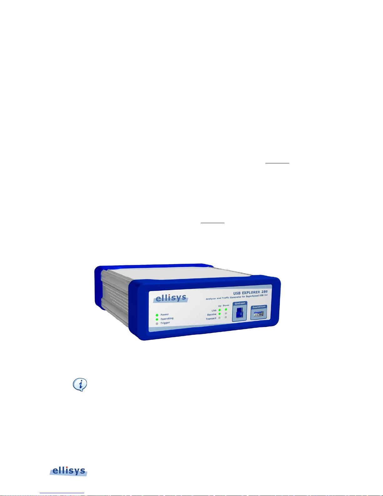
Figure 1-1 Explorer 280 SuperSpeed U S B Protocol Analyzer/Generator ....................... 12
Figure 1-2 Examiner Application ............................................................................. 13
Figure 1-3 Sample HTML Compliance R eport ............................................................ 14
Figure 3-1 USB Explorer 280 .................................................................................. 25
Figure 3-2 Examiner Setup for D ev ic e ( or hub upstream port) ................................... 26
Figure 3-3 Examiner Setup for Testing Host ............................................................. 27
Figure 3-4 Examiner Setup for Testing Hub Downstream-Facing Port .......................... 28
Figure 3-5 Test Setup for Hu b Ch a pter 10 T es ts ....................................................... 29
Figure 3-6 Test Setup for Hu b Ch a pter 10 T es ts ( W ithout Analyzers) .......................... 30
Figure 3-7 USB Explorer 280 Front Panel ................................................................. 33
Figure 3-8 USB Explorer 280 Ba c k Panel ................................................................. 36
Figure 4-1 Examiner Application - Tests Tab ............................................................ 38
Figure 4-2 Examiner Application - Results Tab ......................................................... 39
Figure 4-3 Examiner Application - Settings Tab ........................................................ 40
Page 10
10 of 124
Examiner User Guide
About This Manual
Typographic Conventions
Bold is used to indicate menu commands, buttons, and tabs.
Italics are used to indica te fields, pane names, win dow names and cross references.
Fixed width is used to indicate system file names, text typed and code snippe ts .
A warning symbol- describes a possible cr itical situation and how to avoid it.
An information symbol- tells you how to respond to a situation that may arise.
A tip symbol- tells y ou information tha t will help you carry out a procedure.
Where to Find More Help
Go to the Ellisys website and the following pages for the latest information:
Ellisys products page - Go to for the latest product infor m a tion and documentation.
Application notes and white papers - Go to www.ellisys.com/technology/ to find
up-to-date information about the technology.
Distributors - Go to
www.ellisys.com/sales/ to find a list of Ellisys distributors .
Technical support - Go to www.ellisys.com/support/ to send a question directly to
the Ellisys suppor t te am.
Page 11

Examiner Overview | 11 of 124
SuperSpeed USB Explorer 280
Terms and Abbreviations
Term/Abbreviation Definition
CV Test Driver The driver runn ing on the host control ler, provided
by USB-IF. This driver has a known behavior in
order to run certain tests described in this
document.
Link Verification
System
The EX280 hardware and application aimed at
running the tests on an Upstream or a
Downstream Port U nder Test. The Lin k
Verification System (Examiner) will act as the
opposite port.
LVS See Link Verification System.
Port Under Test The port connected to the Link Verification
System, upon which the tests are run.
PUT See Port Under Test.
Upstream Port A peripheral device (or an upstream-facing hub
port). See Figure 3-2 Examiner Setup for Device
(or hub upstream port).
Downstream Port A host controller (or a downstream-facing hub
port). See Figure 3-3 Examiner S etup for Host (or
hub downstream port).
HUT Hub Under Test
DFP Downstream-Facing Port
UFP Upstream-Facing Port
Page 12
12 of 124 | Examiner Overview
Examiner User Guide
1. Examiner Overview
1.1 Introduction
The Ellisys Examiner™ Compliance Test Suite is a stand-alone application that is used to verify
proper operation of a USB 3.0 host, hub, or device, based on requirements as set forth in the
USB 3.0 specification and other relevant documents as provided by the USB Implementers
Forum (USB-IF). For more information on documents provided by the USB-IF, please visit
www.usb.org.
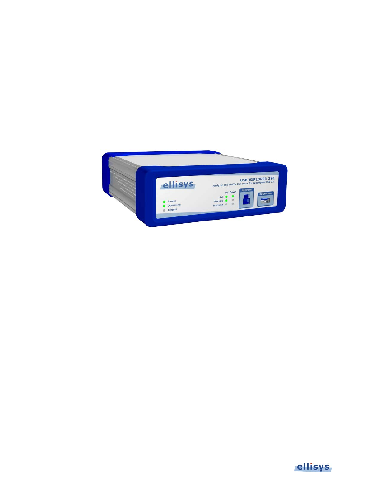
Figure 1-1 Explorer 280 SuperSpee d U S B P rotocol Analyz er/Generator
Page 13
Examiner Overview | 13 of 124
SuperSpeed USB Explorer 280
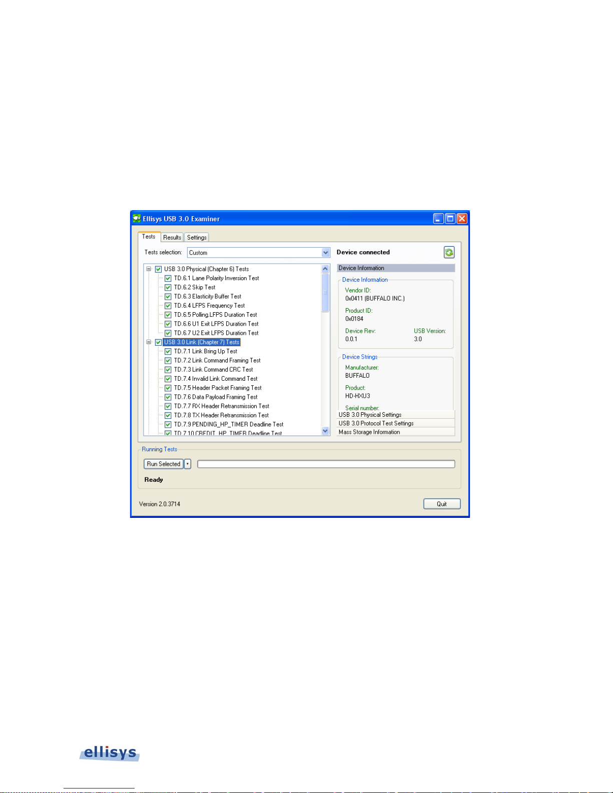
The Examiner application uses an enabled USB Explorer 280 system to emulate a host when
testing a device (or hub upstream port), or to emulate a device when testing a host (or hub
downstream port). For Chapter 10 testing, two enabled EX280s are used to emulate US and DS
ports of the hub under test (HUT). See Section 3, Hardware Setup and Configurations for
details.
Optionally, an Explorer 280 analyzer (EX280A) can be placed in-line between the EX280 running
Examiner and the port under test (PUT), in order to capture the activity and store traces
between Examiner and th e PUT for later review.
Figure 1-2 Examiner Application
Page 14
14 of 124 | Examiner Overview
Examiner User Guide
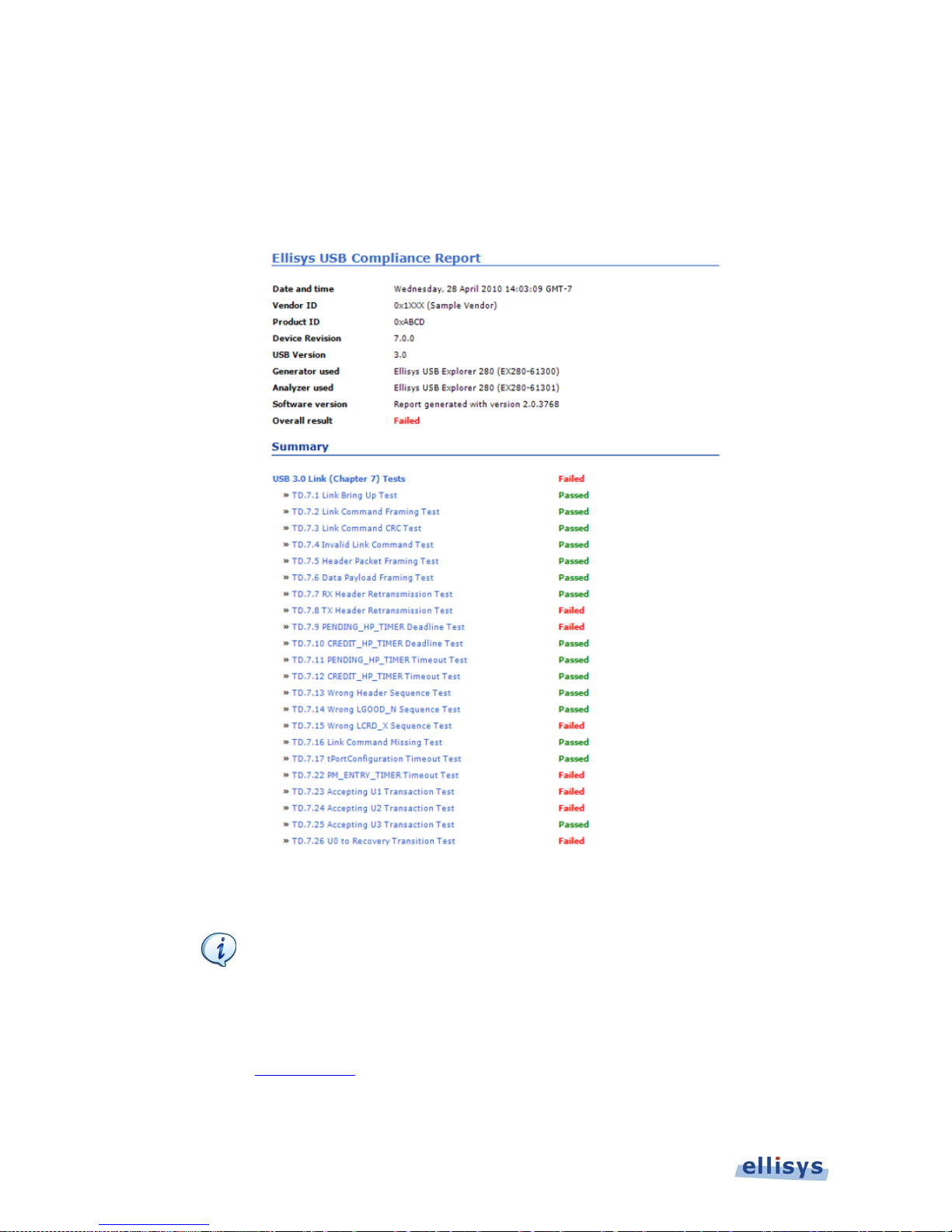
Once initiated by the user, testing progresses automatically, with pass/fail decisions made in
hardware by the Explorer 280 system executing the Examiner application. Pass/fail results are
provided to the user in real-time during testing and also summarized in an HTML report made
available at the completion of testing (see figure 1-3 below), which includes links to
automatically s a ved traces for each test, as captured by the analyzer.
Figure 1-3 Sample HTM L Compliance Report
The EX280 unit being used to operate Examiner may be otherwise
enabled as an EX280 Generator or EX280 Analyzer (or both, in the
case of the EX280 Duo). Examiner is an optional feature and must be
specifically enabled on the EX280 hardware. For information on
updating an Explorer 280 to include the Examiner functionality, please
contact Ellisys.
Page 15

Examiner Overview | 15 of 124
SuperSpeed USB Explorer 280
1.2 Main Features and Areas of Test Coverage
Examiner includes the features and capabilities listed below. Successful completion of Chapter
6/7 tests (commonly referred to as “Link Layer Tests”) and Chapter 10 tests for hubs are
required
for certification by USB-IF. Click here for details from the USB Implementer’s Forum
(USB-IF). Examiner and the Explorer 280 are approved by USB-IF for these tests.
Chapter 6/7 Link Layer testing of a DS port (host c ontroller or hub).
Chapter 6/7 Link Layer testing of an US port (peripheral device or hub).
Chapter 10 H ub tests (US and DS ports).
Chapter 9 (D evice Framework).
Electrica l tests for Voltage, Power, and Current in U0, U1, U2, and U3 states.
Mass Storage Class.
Some tests are conducted in three diff erent device states (Default,
Addressed, and Configu r ed) . Expected results for each state teste d
may vary.
Default State: The device is attached, powered, bu t has not been
assigned a unique address . D ev ic e r es pon ds a t the default address
(0).
Addressed State : Device is attached, powered, and has been
assigned a unique (non-zero) address, but has not been configured.
Configured State: Device is attached, powered, ha s been assigned a
unique (non-zero) address, and has been configured by Examiner to
use the function provided by the device.
In some cases, Examiner may be referred to as the Link Verification
System (LVS). This is intended to maintain consistency with USB-IF
compliance documents and proc edures. These terms may be
considered synonymous within this manual.
Page 16

16 of 124 | Installing the A pp lic a tion
Examiner User Guide
2. Installing the Application
2.1 Software Prerequisites
Before installing the Examiner software application, please ensure the computer system on
which it will reside meets the requirements listed below. To request the Examiner applicat ion,
please click here.
Microsoft Windows XP SP1 or later or Windows 7
Microsoft Windows Installer 3.0 or later. If the installation does not run smoothly, or if
the system indicates a version error, update your Windows installer.
Microsoft .NET F r amework version 2.0 or later.
Intel Core, 1.5 GHz or compatible processor, or bette r .
512 MB RAM or more.
1280 x 1024 scr een display res olution with 65,536 color s , or better.
USB 2.0 EHCI Hos t Controller.
Examiner requires several software components. Ellisys recommends that you visit the
following web pages as needed, to update your versions of Microsoft .NET Framework and
Windows:
www.microsoft.com/net to download the Microsoft .NET Framework version 2.0.
www.update.microsoft.com to update your version of Windows. When using the
Windows update service it will automatically download and install the Microsoft .NET
Framework version 2.0.
See your system administrator for more information about updating Microsoft .NET Framework
and Windows.
2.2 Software Installation
1. Insert the CD-ROM or other storage media that accompanies the product into the
computer’s CD-ROM (or other) drive, or alternatively, download and launch the installer
application from the Ellisys website. Contact Ellisys if you need a link to download the
software application.
Page 17
Installing the A p plic ation | 17 of 124
SuperSpeed USB Explorer 280
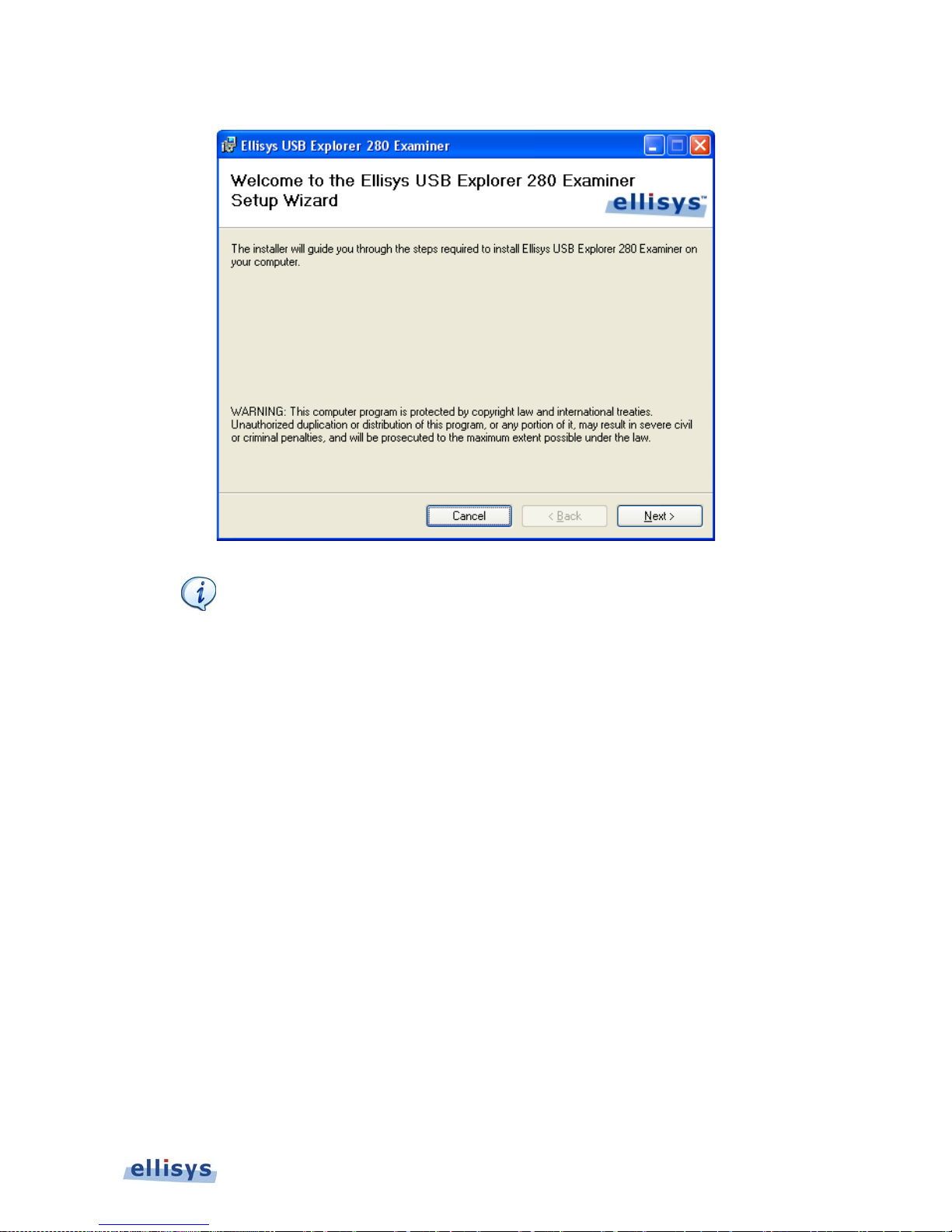
The Examiner Setup Wizard screen appears:
If the Examiner Setup Wizard does not appear automatically, navigate
to the location of the EllisysUSB30Examiner installer file through the
Windows director y and launch the ins ta lle r directly.
2. Read the WARNING note and click on Next.
Page 18
18 of 124 | Installing the A pp lic a tion
Examiner User Guide
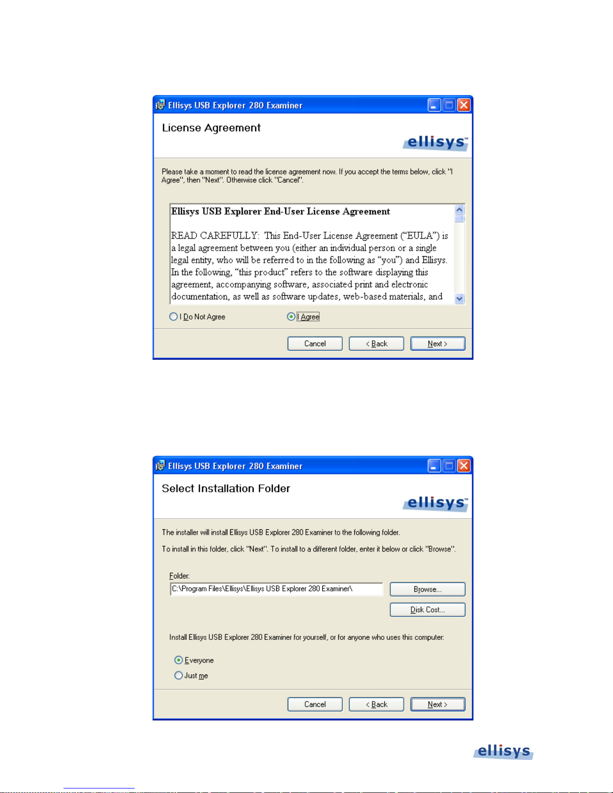
The License Agreement screen appears:
3. Read the License Agreemen t c a refully, and then select I Agree.
4. Click on Next.
The Select Installation F older screen appears.
Page 19
Installing the A p plic ation | 19 of 124
SuperSpeed USB Explorer 280
5. The default installation folder appears in the Folder field. Ellisys recommends that you use
the default folder, however if you wish to change this folder, click on Browse and navigate
to the folder required.
6. Select whether anyone or only the user currently logged on can access the software by
selecting either Everyone or Just me. Click on Next.
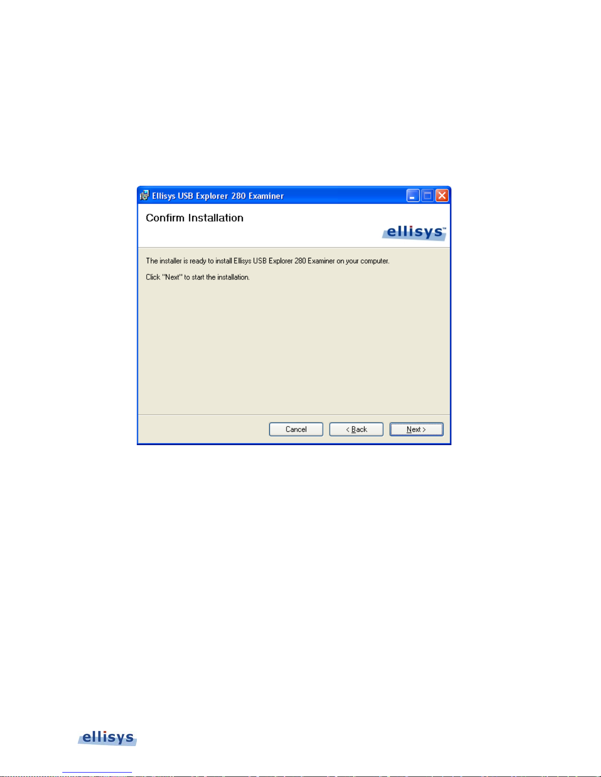
The Confirm Installation screen appears:
7. Click on Next to continu e the installation.
Page 20
20 of 124 | Installing the A pp lic a tion
Examiner User Guide
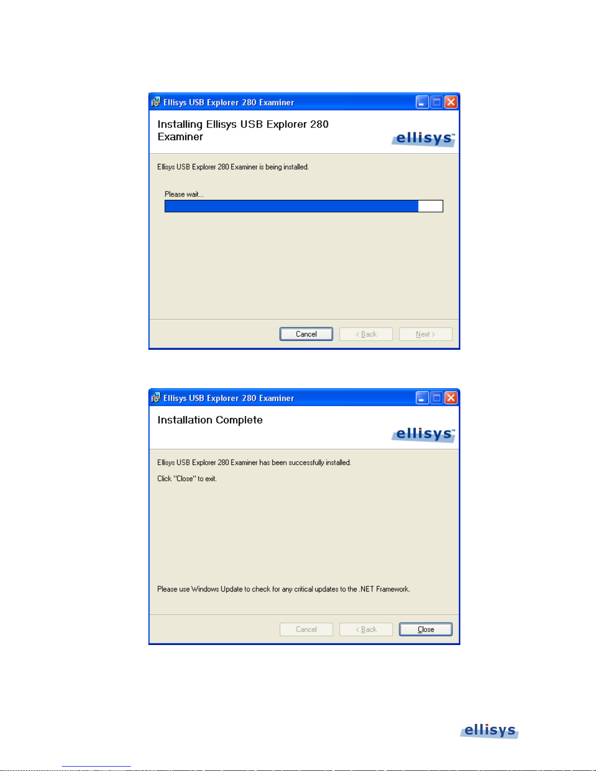
An Installation Progress screen appears:
When the software has been ins ta lled, th e Installation Complete screen appears:
8. Click on Close.
The Ellisys USB Explorer 280 Examiner application is now installed.
Page 21
Installing the A p plication | 21 of 124
SuperSpeed USB Explorer 280
After installing Examiner, a New Hardware Wizard will appear the first
time the Explorer 280 back-panel USB port is connected to your PC.
Refer to section 2.3, Connecting to the Control Computer, for more
information abou t installing the USB driver.
2.3 Connecting to the Control Computer
Examiner, and the USB Explorer 280 Analyzer that may optionally be used in the Examiner
setup (see Figure 3-2 and Figure 3-3), are controlled over a high-speed USB 2.0 connection by
a PC hosting the Examiner application, enabling the use of any notebook or desktop computer.
The USB driver for the Explorer 280 must be installed before Examiner can be used.
Although the unit can upload or download data on a full speed USB 1.1
connection, Ellisys strongly recommends that you connect it to a high
speed USB 2.0 port to obtain optimal performance. If you experience
problems with Examiner, please ensure the Explorer 280 executing
Examiner is connected to a high speed USB 2.0 port before contacting
technical suppor t.
Follow the steps be low to install the USB driver:
Connect a USB 2.0 cable between the Type B USB receptacle on the Explorer 280 back panel
and the PC. If attaching the Explorer 280 for the first time, wait until Windows displays a
message indicating that a new device has been foun d (typicall y a small bubble indication at the
lower-right of the screen), then go to step 3.
To update a previousl y installed device driver:
1. Open the Device Manager: Start | Control Panel (on some operating systems, the Device
Manager icon is pr e s e nt at this step, if so, p roceed to step 4).
2. Double-Click th e System icon.
3. Click on the Har d ware tab.
4. Click on Device Manager.
5. Click on Ellisys protocol analyzers.
6. Right-click and select Update Driver.
Page 22
22 of 124 | Installing the A pp lic a tion
Examiner User Guide
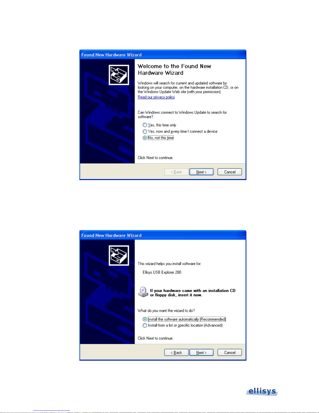
The Hardware Update Wizard opens:
7. Select No, not this time.
8. Click on Next.
The Found New Hardware Wizard appears:
9. Select Install the s oftware automatically (Recommen de d) .
Page 23
Installing the A p plic ation | 23 of 124
SuperSpeed USB Explorer 280
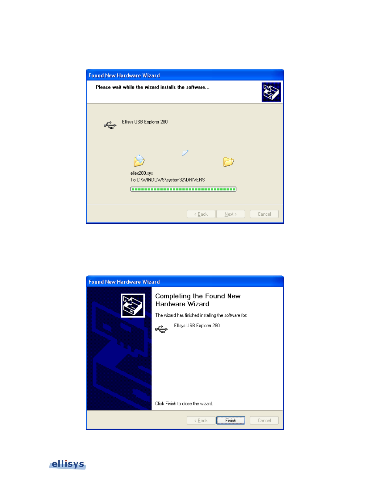
10. Click on Next.
The Please wait while the wizard installs the s oftware window appears :
Windows installs the driver.
11. When the installation is complete, the wizard has finished installing the software screen
appears:
12. Click on Finish.
Page 24

24 of 124 | Installing the A pp lic a tion
Examiner User Guide
The installation is complete.
Page 25
Hardware Setup and Conf igura tion s | 25 of 124
SuperSpeed USB Explorer 280
3. Hardware Setup and Configurations
Examiner uses the USB Explorer 280 Analyzer/Generator in a traffic generation mode to
automatically execute compliance testing against the port under test (PUT). Optionally, an
Explorer 280 Analyzer may be used, under automated control of the Examiner application (or
manually operated under the EX280 Analyzer application), to capture traffic that occurs during
each test that is executed.
This section describes test setups for the following cases :
Section 3.1
Device and Host Link Layer Tests (Chapters 6/7). These are required for USB-IF
certification for USB3.0 devices, hubs, and hosts.
Device Framework (Chapter 9), Electrical, and Mass Storage.
Section 3.2
Hub Testing (Chapter 10). This test suite is required for USB-IF certification of USB 3.0
hubs.
Figure 3-1 USB Explorer 280
The Explorer 280 Analyzer and the Explorer 280 Generator are
identical in appearance and in hardware design. The functionality of
the Explorer 280 (analyzer, generator, or Examiner) is driven by the
software application attached to th e unit.
Page 26
26 of 124 | Hardware Setup and Configurations
Examiner User Guide
3.1 Setup for Link Layer, Device Framework,
Electrical, and Mass Storage Testing
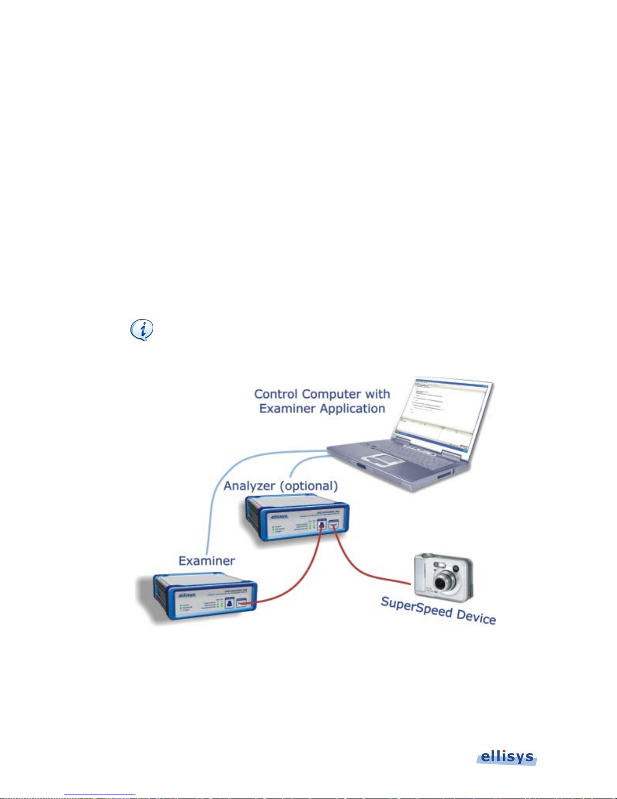
To set up Examiner to t est a device (or hub upstream port):
Connect as shown in the figure below, connecting a USB 2.0 cable from the Control Computer
hosting the Examiner application to the rear control port of the USB Explorer 280 that will
execute the Examiner’ s tests .
Optionally, connect another USB 2.0 cable to the rear control port of an Explorer 280 Analyzer
in order to capture the traffic occurring between the PUT and Examiner. Examiner will control
the analyzer a s w ell. If not connecting the analyzer, the USB 3.0 cabling may be installed direct
from Examiner to the PUT. If the analyzer is used, a second USB 3.0 cable is required between
the analyzer and the PUT as shown below.
The DC power supp lies for the Examiner uni t and the analyzer uni t are
not shown in the Figure below, bu t a r e r equired.
Figure 3-2 Examiner Setup for Device (or hub upstream port)
Page 27
Hardware Setup and Conf igura tion s | 27 of 124
SuperSpeed USB Explorer 280
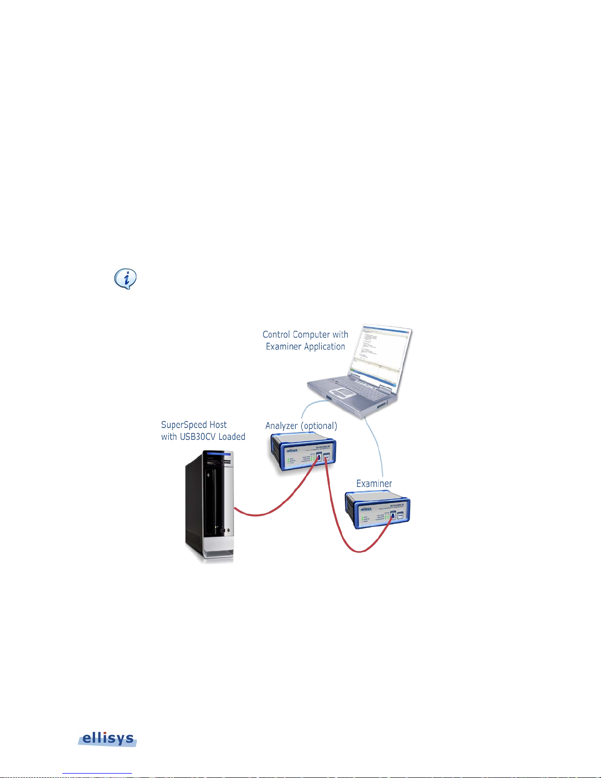
To set up Examiner to test a host:
Connect as shown in the figure below, connecting a USB 2.0 cable from the Control Computer
hosting the Examiner application to the rear control port of the USB Explorer 280 that will
execute the Examiner’ s tests .
Optionally, connect another USB 2.0 cable to the rear control port of an Explorer 280 Analyzer
in order to capture the traffic occurring between the port under test (PUT) and Examiner.
Examiner will control the analyzer as well. If not connecting the analyzer, the USB 3.0 cabling
may be installed direct from Examiner to the PUT. If the analyzer is used, a second USB 3.0
cable is required between th e a nalyzer and the PUT.
Ensure USB30CV is loaded on th e host under test.
The DC power supplies for the Examiner unit and the analyzer unit are
not shown in the Figure below, bu t a r e r equired.
Figure 3-3 Examiner Setup for Testing Host
Page 28
28 of 124 | Hardware Setup and Configurations
Examiner User Guide
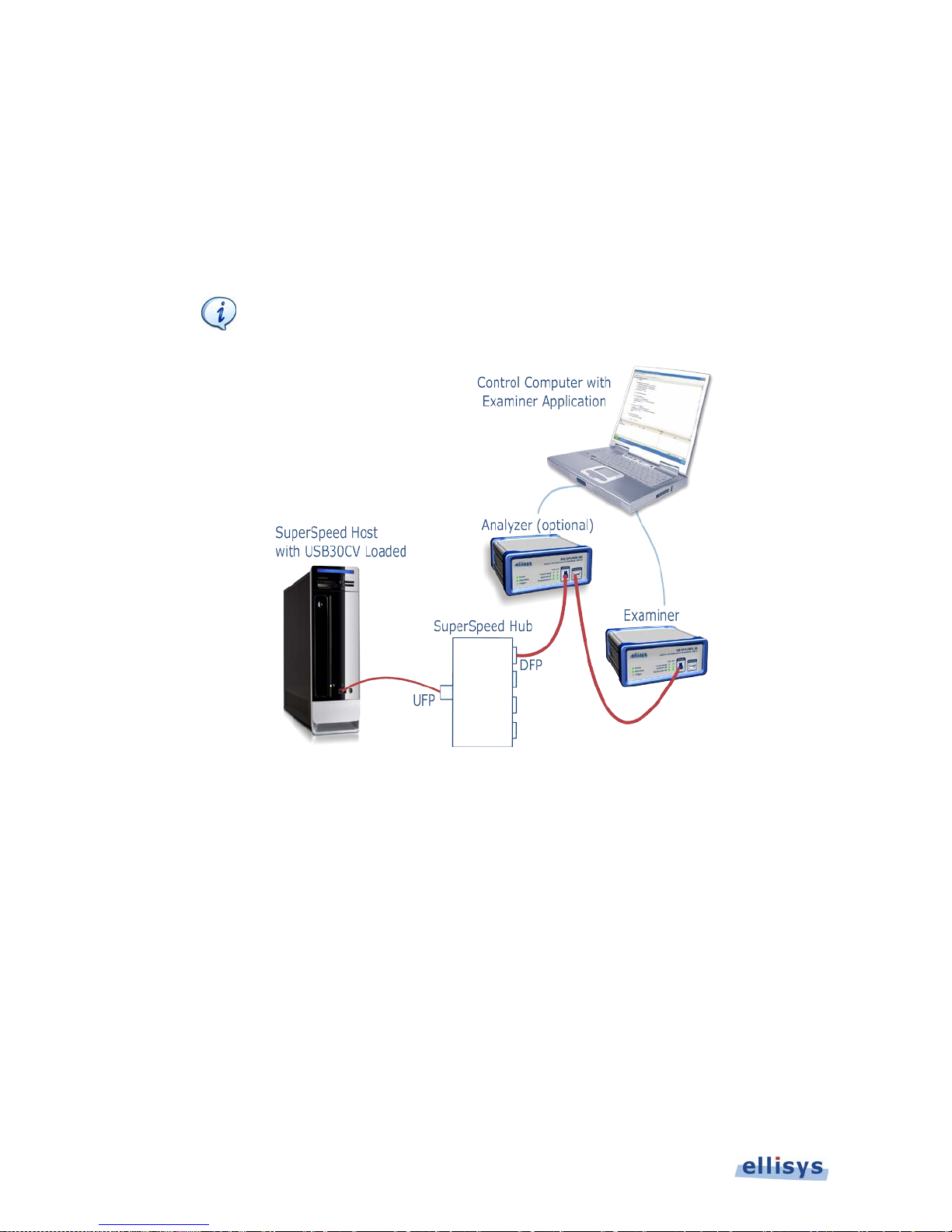
To set up Examiner to test a hub downstr eam-facing port:
For testing of a Hub downstream-facing port (DFP), the upstream-facing port of the hub must
be connected to a host system that has USB30CV installed. Connect as shown in the figure
below.
Ensure USB30C V is loaded on the host system.
The DC power supplies for the Examiner unit and the analyzer unit are
not shown in the Figure below, bu t a r e r equired.
Figure 3-4 Examiner Setup for Testing Hub D ownstream-Facing Port
Page 29
Hardware Setup and Conf igura tion s | 29 of 124
SuperSpeed USB Explorer 280
3.2 Setup for Chapter 10 Hub Testing
To set up Examiner to test a hub:
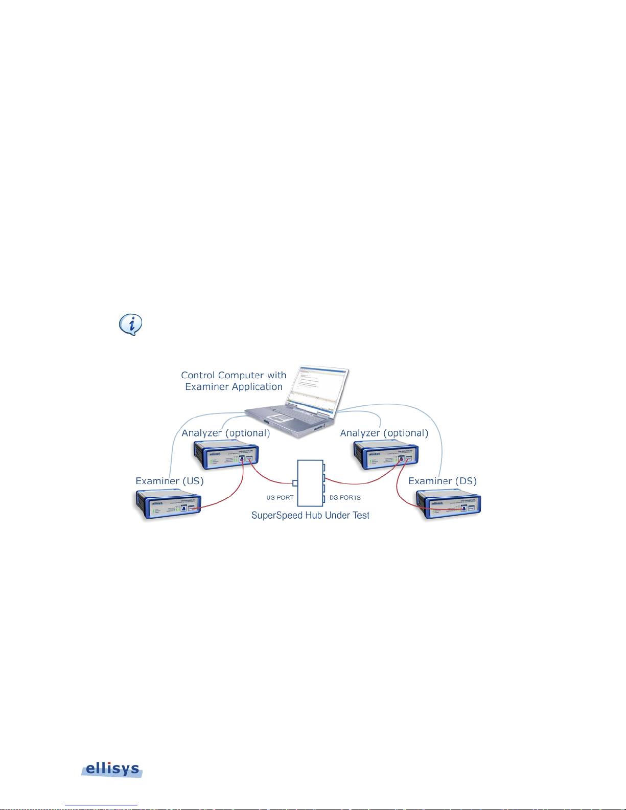
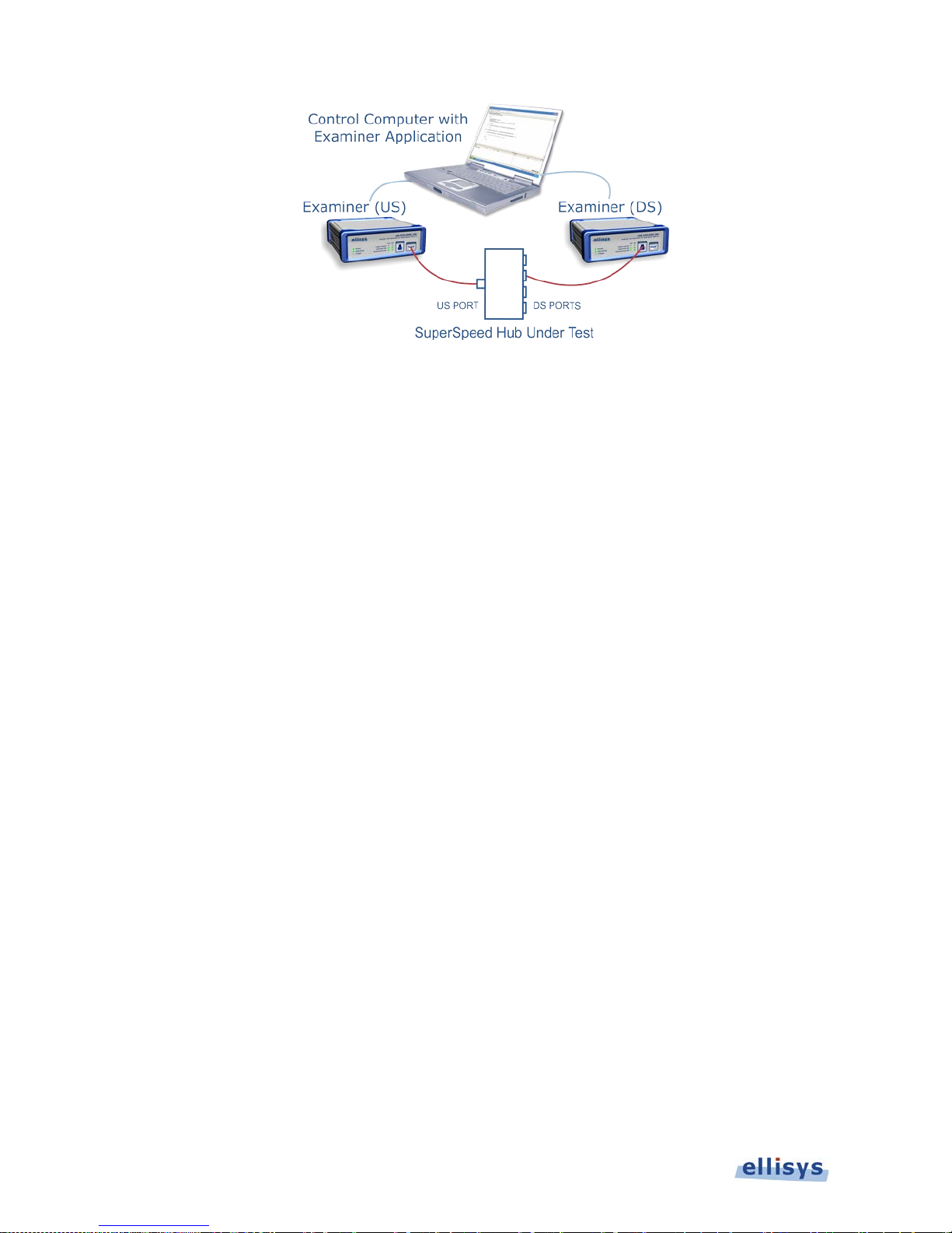
Connect as shown in Figure 3-5 Test Setup for Hub Chapter 10 Tests or Figure 3-6 Test Setup
for Hub Chapter 10 Tests (Without Analyzers) below, connecting a USB 2.0 cable from the
Control Computer hosting the Examiner application to the rear control ports of both USB
Explorer 280’s that will execute the Examiner’s tests (US and DS).
Optionally, connect USB 2.0 cables to the rear control ports of both Explorer 280 Analyzers, in
order to capture the traffic occurring between the US port under test (PUT) and Examine r (US),
and between the DS port under test (PUT) and Examiner (DS). Examiner will control the
analyzer(s) as well. If not connecting the analyzers, the USB 3.0 cabling may be installed direct
from Examiner to the PUT, as shown in Figure 3-5. If the analyzers are used, a second USB 3.0
cable is required between th e a nalyzers and the hub under test (one cable US, one cable DS).
The DC power supplies for the Examiner units and the analyzer units
are not shown in the Figure below, but are required.
Figure 3-5 Test Setup for Hub Chapter 10 T ests
Page 30
30 of 124 | Hardware Setup and Configurations
Examiner User Guide
Figure 3-6 Test Setup for Hub Chapter 10 T ests (Without Analyzers)
Page 31
Hardware Setup and Configurations | 31 of 124
SuperSpeed USB Explorer 280
3.3 Using USB30CV
If testing a hub downstream-facing port (DFP), the upstream port of the hub must be connected
to a host system with USB30CV installed. USB30CV is an application provided by the USB-IF
(www.usb.org) that is used for link layer and hub testing, as well as other compliance test areas
outside the scope of this document.
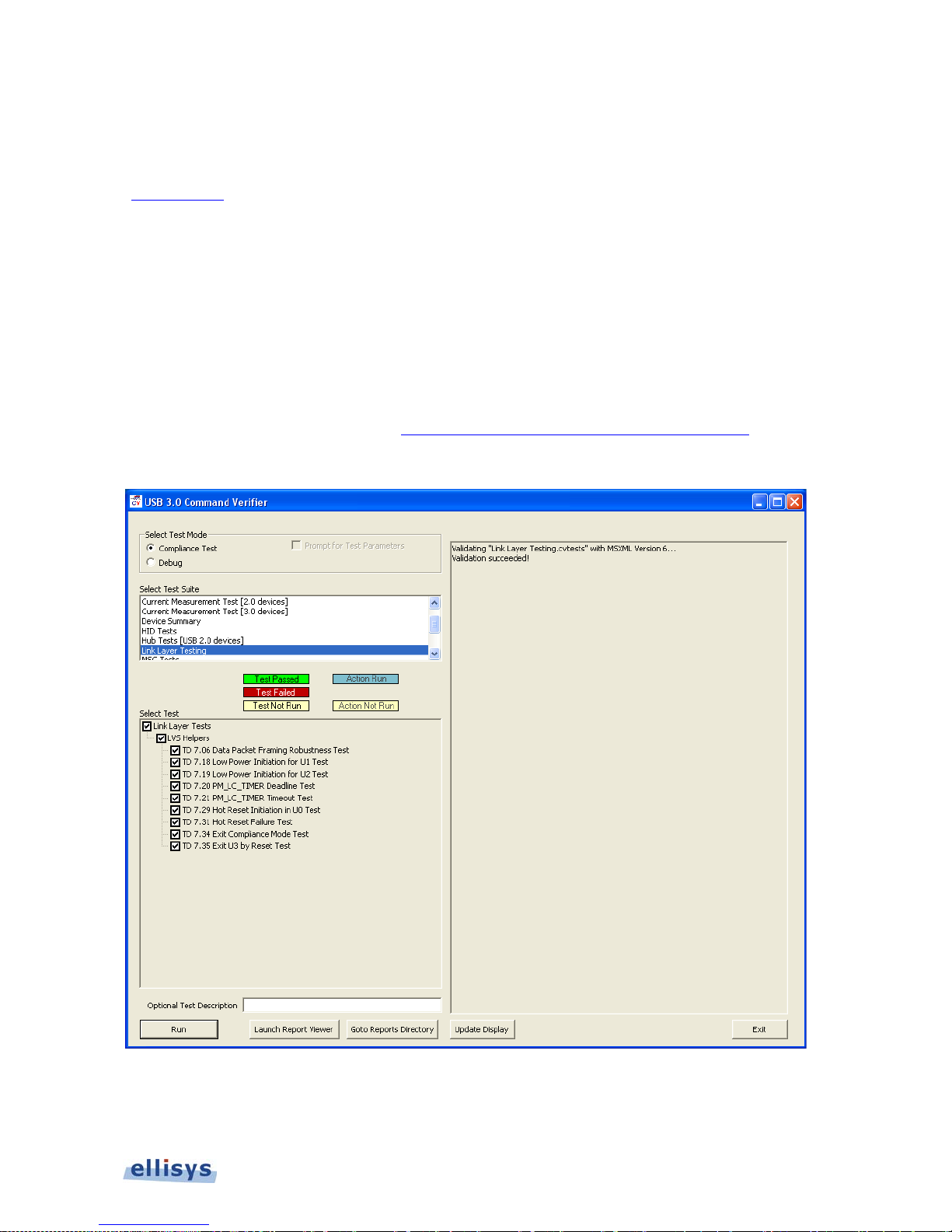
USB30CV will control some of the Link Layer tests in conjunction with Examiner (as shown in
the figure below), and will also provide VBUS to the hub, which is required for all Link Layer
tests on a hub downstream port.
If testing a host port, please ensure USB3.0CV is loaded on the host under test as USB3.0CV
will control some of the Link Layer tes ts in conjunction with Examiner.
To download USB30CV, follow this lin k
http://www.usb.org/developers/ssusb/ssusbtools
The USB30CV Interface is shown below:
To Initiate USB30CV for support of Link Layer Host and Hub D F P Tests:
1. Setup for Host or Hub DFP tests as described in the figures above.
Page 32
32 of 124 | Hardware Setup and Configurations
Examiner User Guide
2. Launch USB30CV on the host system unde r test, or the host sy s te m a ttached to the
upstream-facing port of the hub under test, a s a pplica ble.
3. In USB30CV, select Link Layer Testing from the Select Test Suite box.
4. Click Run on the USB30CV application.
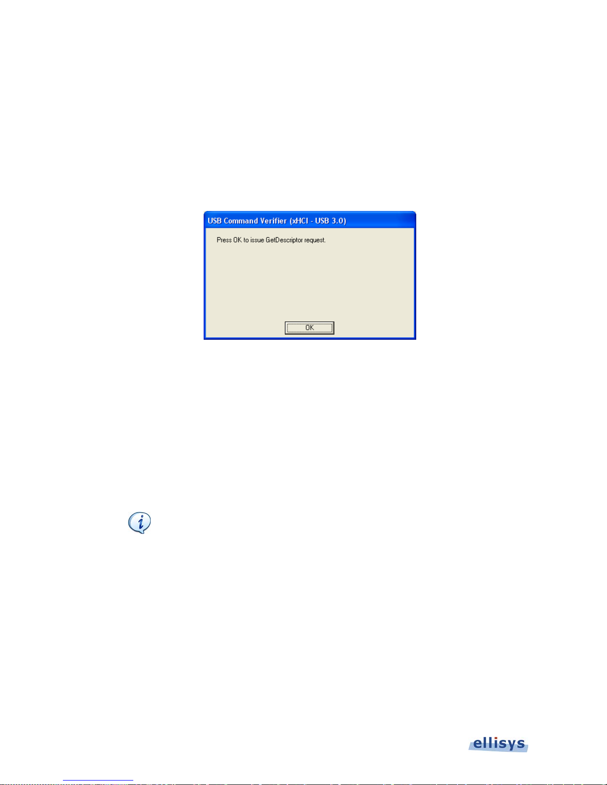
The USB30CV advanc es to the f irs t test to be supported (TD 7.06) and presents a message
such as shown below:
At this point, the u ser will execute the selected Examiner tests (in the Examine r application)
until Examiner d is p la ys a dialog instruc ting the user to initiate an action on CV, such as issuing
a Get Descriptor request as sh own above.
For any further Examiner tests that require USB30CV initia tion of host-side actions (such as
sending the Get Descriptor r equest above), Examiner will provide a dia log instructing the user
to initiate this a ction on USB30CV.
To run USB30CV in Debug Mode:
Debug mode on the USB30CV application allows the user to specify
which tests are to b e r un.
1. Select Debug from the Select Test Mode option on the USB30CV application.
2. Select one (or more) or check boxes associated w ith the tests desired to be exec uted in
the Select Test Box on USB30CV application.
3. Click Run on the USB30CV application.
4. Run the selected tests from the Examiner Application.
Page 33
Hardware Setup and Conf igura tion s | 33 of 124
SuperSpeed USB Explorer 280
To Exclude USB30CV te sts f rom Examiner (run all tests except those using USB30C V):
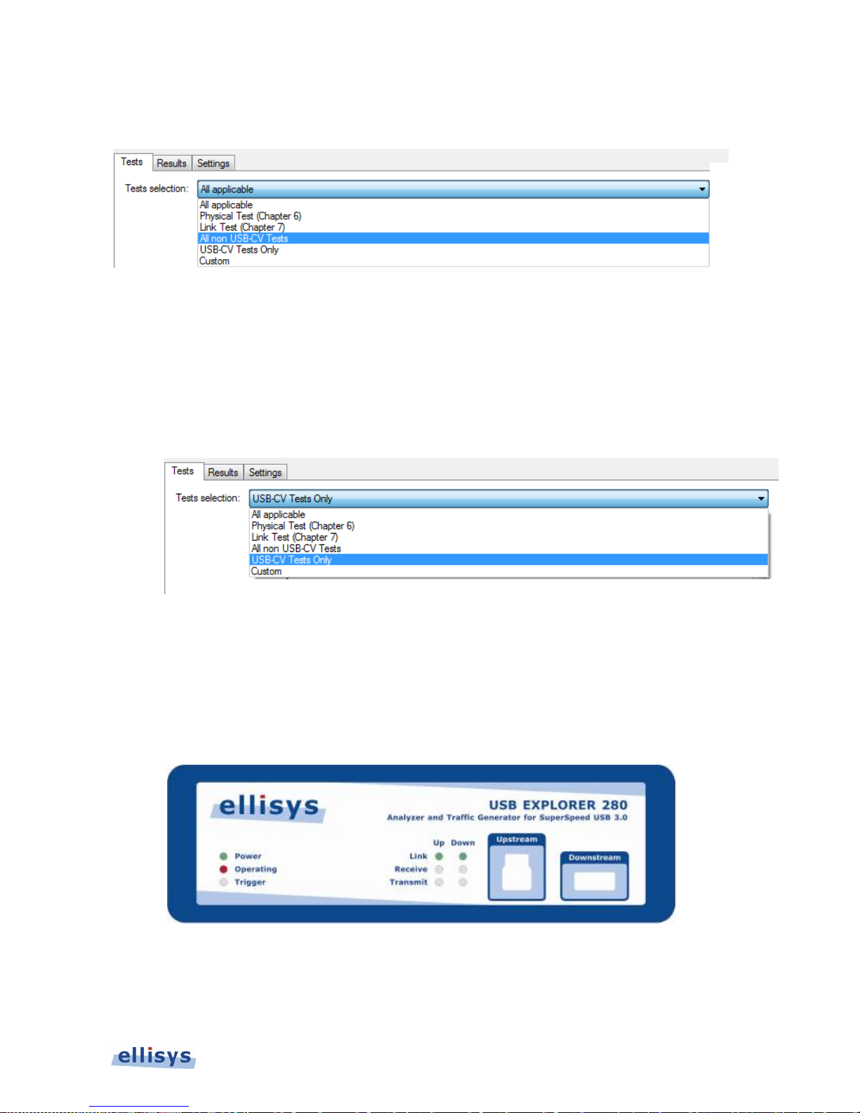
1. Select All Non USB -CV Tests from the Tes ts Selection drop-down on Examiner.
All tests requiring CV are exc lu ded from the Examiner’s test list. USB30CV is not needed for
this test selection.
To Run only USB30CV tests:
1. Select USB-CV Tests Only from the Tests Selection drop-down menu on Examiner.
All tests requiring USB30CV are populated in Examiner ’ s Test List. Tests not requ iring the use
of USB30CV ar e not a vailable.
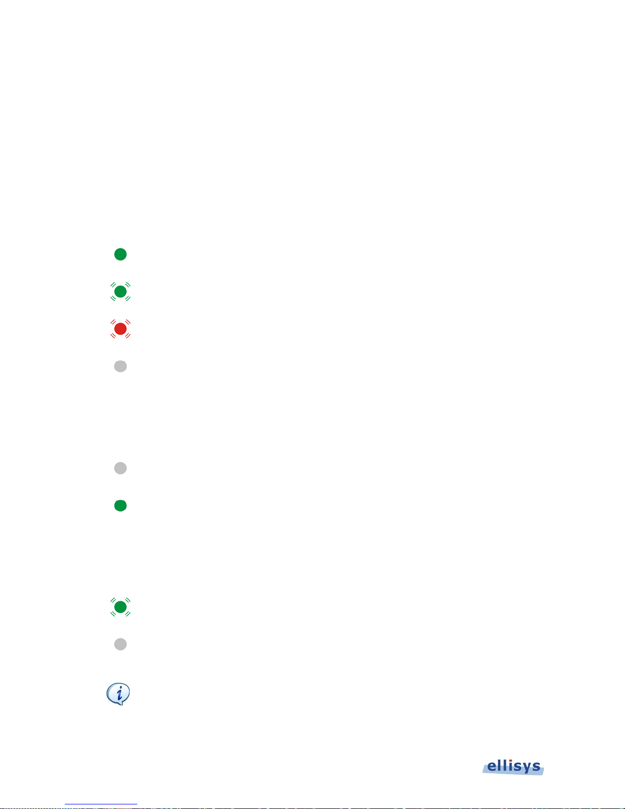
3.4 USB Explorer 280 Front Panel Overview
The front panel of the USB Ex plorer 280 is s hown below:
Figure 3-7 USB Explorer 280 F ront Panel
Page 34
34 of 124 | Hardware Setup and Configurations
Examiner User Guide
Upstream Connector
The Upstream Connector is used in by Examiner when testing a host or hub downstream port.
Downstream Conne c tor
The Downstream Connector is used by Ex a m in er wh en testin g a device or hub upstream port.
Power LED
The Power LED indicates if the unit is correctly powered from the supplied 24VDC/2A power
adapter and connected to the control computer.
Constant green: Powered and connected, ready to operate.
Flashing green: Powered but not connected.
Flashing red: Connected but not powered.
Off: Not powered and not con nected. The Power LED may also be off if when the
unit is in power-sa ving mode after the control computer has been turned off.
Operating LED
The Operating LED indicates if the u nit is actively in us e by the Examiner applic a tion.
Off: Unit is not in use and available.
Constant green: Unit is in use.
Trigger LED
The Trigger LED indicates whether a trigger event has occur r ed.
Green flash: Trigger event detected.
Off: No trigger event dete c ted.
Trigger events executed by Examiner are controlled by Examiner’s
automated programming s c hema and are not definable by the us er .
Page 35
Hardware Setup and Conf igura tion s | 35 of 124
SuperSpeed USB Explorer 280
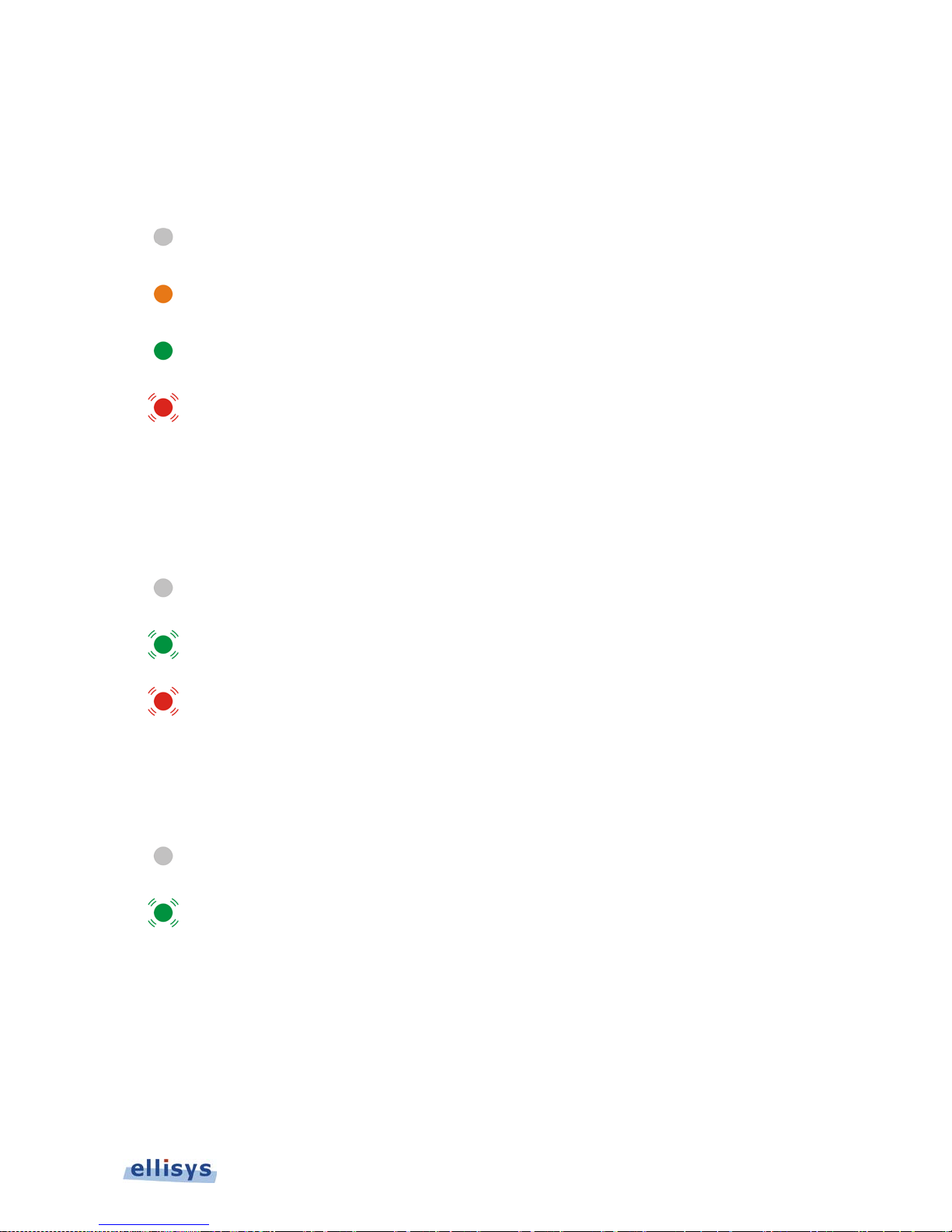
Link LED
The Link LED indicates the status of the Examiner’s upstream and downstream ports. During
Examiner testing, only one of Examiner’s front-panel ports is used: for testing a host, only the
Downstream port is used; for testing a d evice, only the Up s tr e a m p or t is used.
Off: No receiver detected.
Constant orange: Receiver detected, no 5Gb/s SuperSpeed signaling detec ted.
Constant green: 5Gb/s SuperSpeed signaling detected, receiver syn c hronized.
Flashing red: Link is unstable, frequent loss of synchronization.
Receive LED
The Receive LED indicates if payload (Data Packets) or errors (CRC, invalid symbols) are
received on a given port.
Off: No payload or errors detected.
Flashing green: Payload detected.
Flashing red: Errors detected.
Transmit LED
The Transmit LED indicates if payloa d ( D ata Packets) is transmitted on a given port.
Off: No data sent.
Flashing green: Data Packet sent.
3.5 Explorer 280 Back Panel Overview
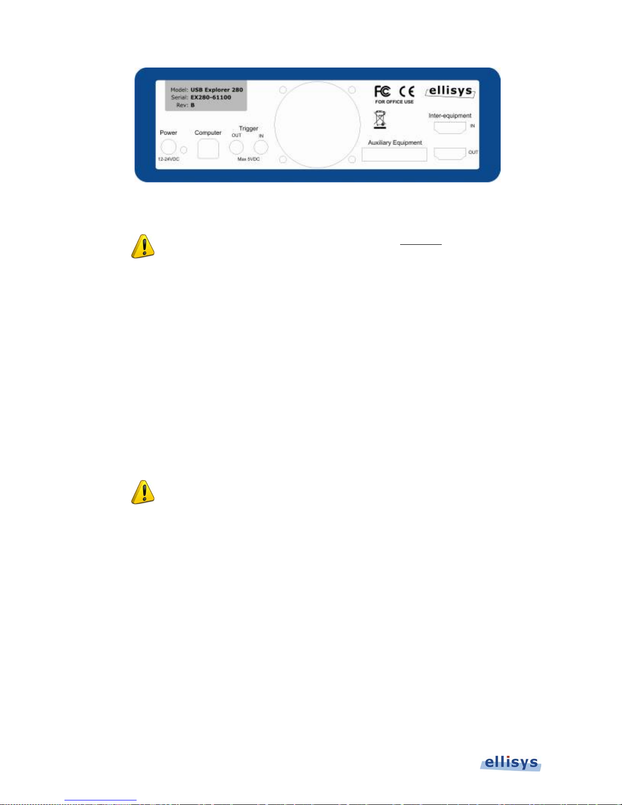
The back panel of the USB Explorer 280 is shown below :
Page 36
36 of 124 | Hardware Setup and Configurations
Examiner User Guide
Figure 3-8 USB Explorer 280 Bac k P ane l
Caution - When connecting the USB cable DO NOT force the
connector into the unit. The metal part of the connector should not be
inserted completely into the connection port. Forcing the connector or
inserting all of the metal part of the connector will break the port
connection and is not covered by the warranty.
Power
DC jack power input. The nearby LED illuminates constant green if a correct voltage is applied,
and illuminates constant red if the v olta ge is applied revers e d.
Accepted Voltage Range: 12V to 24V DC
Minimum Power: 18W
Caution - Use only the DC power supply supplied with Examiner.
Failure to use the supplied DC adapter may result in damage to the
unit.
Computer
Type B USB 2.0 connector. C ontrol port. Attaches to control computer.
Trigger OUT
SMA connector used for sending TTL voltage level shift or pulse to external equipment. Not
used by Examiner.
Trigger IN
SMA connector used for accepting TTL voltage level shift or pulse from external equipment. Not
used by Examiner.
Page 37

Hardware Setup and Conf igura tion s | 37 of 124
SuperSpeed USB Explorer 280
Auxiliary Equipment
Reserved for future ex tensions.
Inter-equipment
Reserved for future ex ten sions .
Page 38
38 of 124 | User Interface Reference
Examiner User Guide
4. User Interface R eference
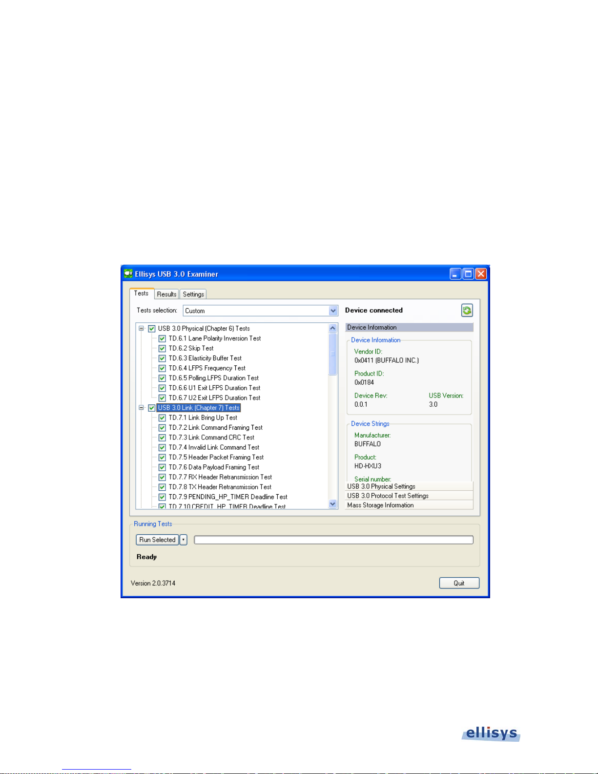
The Examiner user interface consists of three tabs (Tests, Results, and Settings) for test
selection, test results, and environmental settings. Each tab displays specific information
and/or allows the user to in teract with the softw a re for a given task.
4.1 Tests Tab
On the left, shows tests available and selected. Controls for selecting and executing tests are
available. On the right, displays information specific to the connected device under test, and
certain test sett ings.
Figure 4-1 Examiner Application - Tests Tab
Page 39
User Inter face Reference | 39 of 124
SuperSpeed USB Explorer 280
4.2 Results Tab
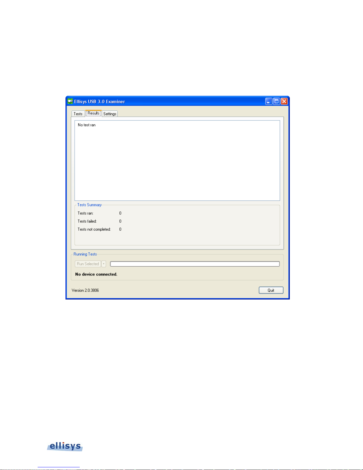
Shows a running tally of all tests conducted, including pass/fail indications, a count of tests run,
failed, and not completed, supplementary results information, and access to the HTML summary
report. Access to the HTML summary report becomes available once all selected tests are
finished.
Figure 4-2 Examiner Application - Results Tab
4.3 Settings Tab
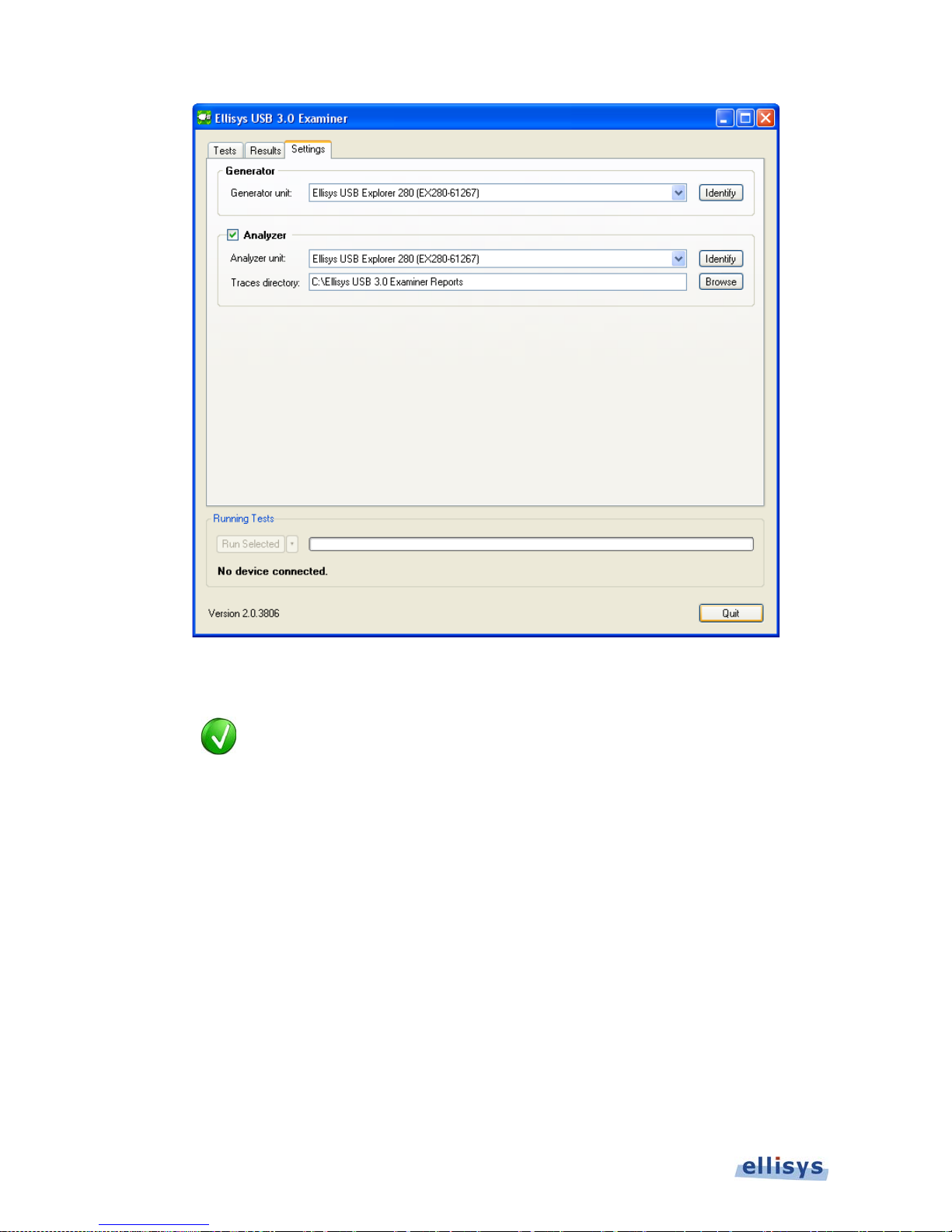
Allows for selection of specific EX280 units for Examiner and (optionally) an EX280 Analyzer.
An Identify button causes the Power LED on the selected EX280 unit to flash when it is
selected. Also provides for user input of a path to write/save the HTML Summary Report and
individual traces associated with each test executed.
Page 40
40 of 124 | User Interface Reference
Examiner User Guide
Figure 4-3 Examiner Ap plication - Settings T ab
In some cases, the user may prefer to capture activity between
Examiner and the PUT using an EX280A anal yzer, without auto mated
control from Examiner (i.e., under the control of the EX280A analyzer
application). To do this, uncheck the Analyzer box in the Settings
tab.
Page 41

Electrical Tests | 41 of 124
SuperSpeed USB Explorer 280
5. Electrical Tests
Some tests are conducted in three different device states (Default,
Addressed, and Configured). Expected results for each state tested
may vary.
Default State: The device is attached, powered, but has not been
assigned a unique address. Device responds at the default address
(0).
Addressed State: Device is attached, powered, and has been
assigned a unique (non-zero) address, but has not been configured.
Configured Stat e: Device is attached, powered, has been assigned a
unique (non-zero) address, and has been configured by Examiner to
use the function provided by the device.
5.1 U0 Power Consumption
Test Summary
This test verifies that t he PUT’s power consumption during U0 is within the correct limits for
configured, addressed, and default states. Examiner will report current, power, and VBus for
each test.
Test Steps and Expected R e su lts
1. Examiner brings the link to the U0 state.
2. Examiner issues one or more standard descriptor requests.
3. Current is measured in the three states shown b elow (in three separate tests):
Configured
Examiner measures current after issuing Set Address(1) and Set Configuration(1) r e quests.
Maximum current m u st be less than 900ma .
Page 42

42 of 124 | Electrical Tests
Examiner User Guide
Addressed
Examiner measures current after issuing a Set Address request to assign a non-zero address to
the device.
Maximum current m u st be less than 150ma .
Default
Examiner measures current after issuing a Device Descriptor request.
Maximum current m u st be less than 150ma .
Specification Reference
Section 11.4.1
5.2 U1 Power Consumption
Test Summary
This test verifies that the PUT’s power consumption during the U1 low-power state is within the
correct limits. Examiner will place the link into U1 from configured, addressed, and default
states, using a Link Manag ement Pac ket (LMP). Examiner will report current, power, and VBus
for each test.
Test Steps and Expe c t ed Results
1. Examiner brings the link to the U0 state.
2. Examiner issues one or more standard descriptor requests.
3. Examiner places the device into each device state (configured, addressed, and default) in
three separate tests before commanding the device to enter U1 in each test. Current i s
measured once the link is in U1, as described below.
4. Examiner issues a Set Link Function a lity LMP with the Force_Link_PM_Accept bit set to one.
5. Examiner issues an LGO_U1 link command.
The device must reply with an LAU link command.
6. Examiner issues an LPMA link command to place th e link into U1.
In all three tests, t he device must draw less than 150ma.
Page 43

Electrical Tests | 43 of 124
SuperSpeed USB Explorer 280
Specification Reference
Section 11.4.1
5.3 U2 Power Consumption
Test Summary
This test verifies that the PUT’s power consumption during the U2 low-power state is within the
correct limits. Examiner will place the link into U2 from configured, addressed, and default
states, using a Link Management Packet (LMP). Examiner will report current, power, and VBus
for each test.
Test Steps and Expe c t ed Results
1. Examiner brin gs the link to the U0 state.
2. Examiner issues one or more standard descriptor requests.
3. Examiner places the device into each device state (configured, addressed, and default) in
three separate tests before commanding the device to enter U2 in each test. Current is
measured once the link is in U2, as described below.
4. Examiner issues a Set Link Function a lity LMP with the Force_Link_PM_Accept bit set to one.
5. Examiner issues an LGO_U2 link command.
The device must reply with an LAU link command.
6. Examiner issues an LPMA link comman d to place the link into U2.
In all three tests, t he device must draw less than 150ma.
Specification Reference
Section 11.4.1
5.4 U3 Power Consumption
Test Summary
This test verifies that the PUT’s power consumption during the U3 low-power state is within the
correct limits. Examiner will place the link into U3 from configured, addressed, and default
states, using the LGO_U3 link command. Examiner will report current, power, and VBus for
each test.
Page 44

44 of 124 | Electrical Tests
Examiner User Guide
Test Steps and Expe c t ed Results
1. Examiner brin gs the link to the U0 state.
2. Examiner issues one or more standard descriptor requests.
3. Examiner places the device into each device state (configured, addressed, and default) in
three separate tests before commanding the device to enter U3 in each test. Current is
measured once the link is in U3, as described below.
4. Examiner issues an LGO_U3 link command.
The device must reply with an LAU link command.
5. Examiner issues an LPMA link comman d to place the link into U3.
In all three tests, t he device must draw less than [2.5ma] 150ma.
Specification Reference
Section 11.4.3
5.5 VBus Acceptance Range Tests
Test Summary
This test verifies that the PUT reaches and maintains U0 across a range of decrementing VBus
levels. Examiner will vary the VBus level from 5.30V to 3.60V in 100mV decrements for each
test. Examiner will report current, power and VBus for each test.
Test results for VBus levels between 3.60V and 4.40V are below required
levels (per specification) and are advisory only.
Test Steps and Expe c t ed Results
1. Examiner brin gs the link to the U0 state using the first VBus level (5.30V).
2. Examiner issues one or more standard descriptor requests.
3. Examiner places the device into each device state (configured, addressed, and default) in
three separate tests, each in c luding all VBus range increments.
4. Examiner measures current, power, and VBus during U0.
Page 45

Electrical Tests | 45 of 124
SuperSpeed USB Explorer 280
The device must reach U0 and maintain U0 until Examiner disables the link.
5. Examiner disables the link to force link recovery then repeats the process for the next VBus
increment to be tested. This proc es s is r epea ted until all increments have been tested.
Specification Reference
Section 11.4.5
Page 46
46 of 124 | Physical Layer
Examiner User Guide
6. Physical Layer
When viewing Physical Layer and Link Layer test activity in the USB
Explorer 280 analyzer software application, it is generally best that the
user disable the “grouping” feature (uncheck Enable Grouping),
located in the Grouping drop-down selection in the USB 3.0
Overview. Disabling grouping leaves the user with the low-level view
needed for a proper understanding of test sequences that are
conducted in Chapters 6 and 7 tests. In some tests however, control
transfers are used, and in these tests the user may find it more
intuitive to leave Grouping enabled.
6.1 Lane Polarity Inversion Test
Test Summary
This test verifies that the PUT can pr op er ly accommodate recep tion of reversed polarity.
Test Steps and Expected R e su lts
1. Examiner reverses polarity on its transmit lines prior to the first TSEQ, trains the link, and
brings the device to U0.
The PUT must achiev e U0 and stay in U0 for at le a st 50ms.
Specification Reference
Section 7.5.4.4.1#1
Page 47

Physical Layer | 47 of 124
SuperSpeed USB Explorer 280
6.2 SKP Test
Test Summary
This test verifies that the PUT supports all possible SKP combinations. Here are the
combinations to be tested:
Repetition of one skip ordered set followed by 354 sy m bols ( word aligned)
Repetition of one skip ordered set followed by 353 sy m bols ( word misaligned)
Repetition of tw o s kip ordered sets followed by 708 symbols (word aligned)
Repetition of tw o s kip ordered sets followed by 707 symbols (word misaligned)
Repetition of three skip ordered sets followed by 1, 062 s ymbols (word aligned)
Repetition of three skip ordered sets followed by 1, 061 s ymbols (word misaligned)
Repetition of four skip ordered sets followed by 1, 416 symbols (word aligned)
Repetition of four skip ordered sets followed by 1,415 symbols (word misaligned)
Test Steps and Expecte d Results
1. Examiner brings the link to U0 as described in TD7.1 (Link Bri ng-Up Test), then uses the
first SKP pattern above (initiated after Examiner completes the TSEQ sequ ence).
Examiner will keep the link active by s ending Link Polling Comm ands (LUP
when it is config ured as an Upstream Port and LDN when it is configured as
a Downstream Port).
Test passes if the PUT achieves U0 and stays in U0 for at least 100ms.
2. Examiner disables the link after 100ms in U0 and repeats the steps above using the ne xt
skip pattern until all skip patterns h ave been tested.
Specification Reference
Section 6.4.3
6.3 Elasticity Test
Test Summary
This test verifies that the PUT’s elasticity buffer supports the whole frequency range of
-5,300ppm to 300ppm (reference clock frequency limits of +/- 300ppm, plus the SSC frequency
delta of 5000ppm).
Page 48

48 of 124 | Physical Layer
Examiner User Guide
Test Steps and Expe c t ed Results
1. Examiner configures with an equivalent S SC clock at -5300ppm.
2. Examiner brings the link to U0 as described in TD7.1 (Link Bring-Up Test).
The test passes if the exchanges are met, no timeout is detected, all packe ts
are successfully received, al l credits are restored, and the link stays in U0 for
at least 50ms.
3. LVS repeats the above steps with an equivalent SSC clock at +300ppm.
Specification Reference
Section 6.4.3
6.4 LFPS Frequency Test
Test Summary
This test verifies that the PUT’s LFPS detector supports the entire LFPS frequency range
permitted. Here are the periods to be t es ted:
tPeriod = 10 M Hz minimum (100ns)
tPeriod = 50 M Hz maximum (20ns)
Test Steps and Expe c t e d Results
1. Examiner and the PUT go through the initial steps of the LTSSM (SS.Inactive, Rx.Detect) to
reach Polling.LF PS.
2. Examiner will start generating a Polling.LFPS signal having nominal durations of tBurst =
1 us and tRepeat = 10 us. The burst period will be set to the first period listed above.
The test passes if the PUT moves successfully to Polling.RxEQ.
3. Repeat the steps above with the second period list ed above.
Specification Reference
Sections 6.9.1 ● 7.5.4.3.2
Page 49

Physical Layer | 49 of 124
SuperSpeed USB Explorer 280
6.5 Polling.LFPS Duration Test
Test Summary
This test verifies that the PUT’s Polling.LFPS detector supports the entire tBurst and tRepeat
duration ranges. Durations to be tested:
tBurst = 0.6 us and tRepeat = 6 us
tBurst = 0.6 us and tRepeat = 14 us
tBurst = 1.4 us and tRepeat = 6 us
tBurst = 1.4 us and tRepeat = 14 us
Test Steps and Expe c t ed Results
1. Examiner and the PUT go t hrough the initial steps of the LTSSM (SS.Disabled, Rx.Detect)
to reach Polling.LF PS.
2. Examiner will generate a Polling.LFPS signal having the first durations specified in the list
above.
3. Repeat the steps w ith the following dura tions listed above.
The test passes if t he PUT moves succe ssfully to Polli ng. RxEQ as per Section
7.5.4.3.2 of the US B 3. 0 specification (Exit from Pollling.LFPS).
Specification Reference
Sections 6.9.1 ● 7.5.4.3.2
Page 50
50 of 124 | Link Layer Tests
Examiner User Guide
7. Link Layer Tests
When viewing Physical Layer and Link Layer test activity in the USB
Explorer 280 analyzer software application, it is generally best that the user
disable the “gro uping” feature (uncheck Ena ble Grouping), located in the
Grouping drop-down selection in the USB 3.0 Overview. Disabling
grouping leaves the user with the low-level view needed for a proper
understanding of test sequences that are conducted in Chapters 6 and 7
tests. In some tests however, control transfers are used, and in these tests
the user may fin d it m or e intuitive to leave Grouping enabled.
In some cases, Examiner may be referred to as the Link Verification
System (LVS). This is intended to maintain consistency with USB-IF
compliance documents and procedures. These terms may be considered
synonymous within this manual.
Certain link layer tests for downstream-facing ports require the use of the
USB30CV tool, operated concurrently with Examiner. USB30CV is available
from the
USB-IF website.
7.1 Link Bring-Up Test
Test Summary
This test verifies that the Link Verification System (LVS) and the Port under Test (PUT) can
reach U0 successfully, and meet other link initialization requirements.
Test Steps and Expe c t ed Results
1. Examiner begins the link initialization process.
If Examiner is configured as an Upstream Port:
Examiner asserts terminations.
The PUT must already be in RxDetect.
The PUT must transmit Polling.LFPS before tRXDetectQ ui e tTi me out (12ms
+50%) + tPollingLFPSEstablished (80us +50%) expires.
Page 51

Link Layer Tests | 51 of 124
SuperSpeed USB Explorer 280
If Examiner is configured as a Downstream Port:
Examiner asserts VBUS and terminations.
The PUT must move to Rx.Detect.
The PUT must transmit Polling.LFPS before tRXDetectQ ui e tTi me out (12 ms
+50%) + tPollingLFPSEstablished (80us +50%) expires.
2. Examiner transmits Polling.LFP S bursts.
The PUT must transmit at least 16 consecutive Polli ng.LFP S.
The PUT must transmit at least 4 consecutive Polling.LFPS after receiving one
Polling.LFPS.
The PUT must NOT progress past Polling.LFP S before Examiner sends at least
2 consecutive Polling.LFPS.
The PUT must progress past P olling.LFPS before tPollingLFPSTimeout expires
(360ms + 50%).
3. Examiner transmits TSEQ ordered sets.
The PUT must transmit TSEQs.
The PUT must NOT transmit SKPs, Idles, or any other packet, symbol, or
ordered set during T S EQ transmission or between TSEQ ordered sets.
4. The LVS transmits TS1 ordered sets and w aits to receive eight consecutive and iden tic al
TS1 or TS2 ordered sets from the P UT.
The PUT must transmit TS1s.
The PUT must NOT transmit TS2s before Examiner sends 8 consecutiv e and
identical TS1s or TS2s.
The PUT must NOT interrupt a TS1 ordere d set to transmit a SKP (between
TS1 ordered sets is permitted).
The PUT must NOT transmit IDLEs or a n y ot her packet.
Page 52

52 of 124 | Link Layer Tests
Examiner User Guide
The PUT must NOT transmit TS1s after tPollingActiveTimeout expires (12ms
+50%).
5. Examiner transmits TS2 ordered sets and readies to complete the Polling.Configuration
handshake.
The PUT must transmit at least 16 consecutive TS2s after receiving one TS2.
The PUT must NOT i nt e r rupt t ransmission of a T S2 ordered set to transmit a
SKP (between TS2 ordered sets is permitted).
The PUT must NOT send IDLEs before Examiner sends at least 8 consecutive
TS2s.
The PUT must NOT i nt e r rupt t ransmission of T S2s to transmit a SKP (between
TS2 ordered sets is permitted).
The PUT must NOT continue to send TS2s after tPollingConfigurationTim eout
expires (12ms +50%).
6. Examiner transmits IDLE symbols.
The PUT must transmit 16 IDLEs after its TS2s.
The PUT must NOT sen d the Header Seque n c e Number and/or Receiver
Header Buffer Credit advertisements before Examiner sends 8 IDLEs.
The PUT must NOT enter recovery after IDLEs have been exchanged between
the PUT and Examiner.
Upon U0 entry, the PUT must transmit the Header Sequence Number and
Receiver Header Buffer Credit advertisements before expiration of their
respective timeouts: Pending_HP_Timer (3us +50%) and Credit_HP_Timer
(5000us +50%).
Examiner will keep the link active by sending Link Pollings (LUP when it is
configured as an Upstream Port and LDN when it is configured as a
Downstream Port) .
Page 53

Link Layer Tests | 53 of 124
SuperSpeed USB Explorer 280
Specification Reference
Sections 7.2.4.1.1#6 ● 8,10-17,22 ● 7.2.4.1.4#2 ● 7.3.4#2 ● 7.5.6.1#5,6 ● 8.4.5#1
8.4.6#1,3 (downstream) ● 8.4.7#1 (upstream)
7.2 Link Co mman d Fr amin g Test
Test Summary
This test verifies that the PUT can tolerate link commands having one symbol error in the
LCSTART framing. The Port Configuration transaction will be used for this purpose. Here are
the combinations to be tested:
ERR SLC SLC EPF (incorrect symbol is D0.0)
SLC ERR SLC EPF (incorrect sy mbol is D0.1)
SLC SLC ERR EPF (incorrect symbol is D 0 .2)
SLC SLC SLC ERR (incorrect symbol is D0.3)
Test Steps and Expe c t ed Results
1. Examiner executes the steps described in TD7.1 (Link Bri ng-Up Test), to bring the link to
U0, but transmits all LCR D_X link commands with an error in the first L CSTART symbol.
The test passes if the exchanges are met, no timeout is detected, all packe ts
are successfully received, al l credits are restored and the link stays in U0 for
at least 50ms.
2. Repeat the steps above with an error in the second, third, and four th L CSTART symbols.
Specification Reference
Section 7.3.4#1, 2
7.3 Link Command CRC Test
Test Summary
This test verifies that the PUT initiates a recovery upon receipt of one corrupt CRC5 in each of
the two link command word (one at a time) and then both CRCs corrupted. The Port
Configuration tr ansaction will be us e d for this purpose.
Reference Errata (June 2010) regarding changes to a port’s handli ng of an
invalid link command (Core Specif ic ation Section 7.3.2).
Page 54

54 of 124 | Link Layer Tests
Examiner User Guide
The tested CRC-5 error conditions a r e:
Incorrect CRC-5 in first Link Command Wor d
Incorrect CRC-5 in second
Link Command Wor d
Incorrect CRC in both
Link Command Wor ds
Test Steps and Expe c t ed Results
1. Examiner executes the steps described in section TD7.1 (Link Br ing-Up Test) to bring t he
link to U0, but tran smits all LCRD_X link commands with the first condition listed above.
The test passes if port under test i nitiates a recovery sequence (upon
expiration of the Credit_HP_Time r at 5000us +50%) as a result of receiving a
link command with o ne or two incorrect CRC5s, and returns to U 0 for at least
50ms.
2. Repeat the step above using th e s ec ond and third conditions listed above.
Specification Reference
Section 7.3.4#2
7.4 Invalid Link Command Test
Test Summary
This test verifies that the PUT will ignore an invalid link command (first and second LCW
containing diff er e nt commands). The tested condit ion is:
Link command with LGO_U1 in the first LCW and LGO_U2 in the second LCW, with good
CRC-5 calculations on both LCWs.
Test Steps and Expe c t ed Results
1. Examiner executes steps described in TD7.1 (Link Bring-Up Test) to bring the link to U0.
2. Examiner sends the link command described above, following the completion of link
advertisement sequences.
The test fails if the port under test replies with LXU or LAU.
The test passes if the link command is ignored, al l exchanges are correct, no
timeout is detecte d, a ll packets are successfully received by the PUT, all
credits are restored and the link stays in U0 for at least 50ms.
Page 55

Link Layer Tests | 55 of 124
SuperSpeed USB Explorer 280
Specification Reference
Section 7.3.4#2
7.5 Header Packet Framing Test
Test Summary
This test verifies that the PUT does not invalidate header packets having one symbol error in
the HPSTART framing. The Port Configuration transaction will be used for this purpose. Here
are the combinati ons to be tested:
ERR SHP SHP EPF (incorrect symbol is D 0 .0)
SHP ERR SHP EPF (incorrect symbol is D 0.1)
SHP SHP ERR EPF (incorrect sy mbol is D0.2)
SHP SHP SHP ERR (incorrect symbol is D0.3)
Test Steps and Expe c t ed Results
1. Examiner executes steps as described in TD7.1 (Link Bring-Up Test), to bring the link to
U0, but transmits all Hea der Packets with an error in the first H PSTART symbol.
2. Repeat the above steps with a n error in the second, third, and fourth HPSTART symbols.
The test passes if the exchanges are met, no timeout is detected, all packe ts
are successfully received by the PUT, all credits are restored and the link
stays in U0 for at least 50ms.
Specification Reference
Section 7.2.4.1.4#1
7.6 Data Payload Framing Test
Test Summary
This test verifies that the PUT does not invalidate data payload packets having a singlecharacter framing error in the DPPSTART and DPPEND framings.
When Examiner is configured as a Downstream Port it will place framing
errors on Setup DP Packets
. When Examiner is configured as an Upstr eam
Port, it will reply to the Get Device Descriptor request with a DPP
containing
framing errors. In this case, the Host will run the CV Link Test Stack in
Page 56

56 of 124 | Link Layer Tests
Examiner User Guide
order to have a known and defined behavior.
Combinations to be tested:
Data Start Framing
ERR SDP SDP EPF (incorrect symbol is D0.0)
SDP ERR SDP EPF (incorrect symbol is D0.1)
SDP SDP ERR EPF (incorrect symbol is D0.2)
SDP SDP SDP ERR (incorrect symbol is D0.3)
Data End Framing
ERR END END EPF (incorrect symbol is D0.0)
END ERR END EPF (incorrect symbol is D0.1)
END END ERR EPF (incorrect symbol is D0.2)
END END END ERR (incorrect symbol is D0. 3)
Test Steps and Expec ted Results
1. Examiner executes the steps described in TD7.1 (L ink Bring-Up Test) to bring the link to
U0. At this stage the Downstream Port (either Examiner or the host port under test) is
expected to issue a Get Device Descriptor request.
If Examiner is configured as an Upstream Port:
a. Examiner prompts the test operator to have the PUT send a GetDeviceDescriptor
request through a USB30CV prompt and then press “OK”.
When Examiner receives the GetDeviceDescriptor request, it closes its
prompt.
b. Examiner will respond to the request correctly, but will send the DPP containing the
Device Descriptor d ata with the f irst framing error liste d above.
The test fails if no GetDeviceDescriptor request is received (assuming the test
operator has pressed “OK”).
Page 57

Link Layer Tests | 57 of 124
SuperSpeed USB Explorer 280
The test passes if the exchanges are met, no timeout is detected, all packe ts
are successfully received by the PUT, all credits are restored an d t he link
stays in U0 for at least 50ms.
If Examiner is configured as a Downstream Port:
a. It will issue a Get Device Descriptor request, but will send the SETUP DP with the first
framing error listed above.
The test passes if the exchanges are met, no timeout is detected, all packe ts
are successfully received by the PUT, all credits are restored and the link
stays in U0 for at least 50ms.
The test fails i f the data exchange fails at the protocol layer (i.e., if the PUT
replies with a TP A CK having the sequen c e number set to zero – indicating the
PUT detected a data payload error).
b. Repeat the testing above for each framing error.
Specification Reference
Sections 7.2.4.1.6#1, 2 ● 8.11.4
7.7 RX Header Packet Retransmission Test
Test Summary
This test verifies that the PUT will send an LBAD if a header packet is incorrectly received, and
that the retransm ission will be correctly handled.
Page 58

58 of 124 | Link Layer Tests
Examiner User Guide
The tested conditions invalidating the hea der pack et are:
Incorrect CRC-16
Incorrect CRC-5
A single K symbol in the HP dat a (see list below), each to be located (one at a time) at
the second and fifth characters after the start framing ordered set.
Position 2: SHP SHP SHP EPF DX.X KX.X DX.X DX.X
Position 5: SHP SHP SHP EPF DX.X DX.X DX.X DX.X KX.X5
K28.2 (SDP)
K28.3 (EDB)
K28.4 (SUB)
K28.6 (Reserved K-symbol)
K27.7 (SHP)
K29.7 (END)
K30.7 (SLC)
K23.7 (EPF)
For the K-Character tests, the Packet’s CRC-16 is first calculated correctly,
then, the K-Character is inserted into the LMP packet. This is done in order
to better simulate an in-flight (transmission) error, rather than a chip error
on the PUT.
Test Steps and Expe c t ed Results
1. Examiner executes steps 1 to 3 of TD7.1 (Link Bring-Up Test) to train the link and
exchange Link Adv er tisements transa ctions.
2. Examiner and the PUT will exchange Port Configuration transactions, but in this case the
first header packet sent by Examiner will be invalid.
If Examiner is configured as an Upstream Port:
a. It waits for the PUT’s Port Cap a bility LMP.
b. It transmits its Port C apability LMP with the first invalid con d ition above.
c. The PUT must respond with an LBAD
d. Examiner transmits a LRTY and then retransmits the packet.
e. Examiner transmits the Port Configuration LM P .
Page 59

Link Layer Tests | 59 of 124
SuperSpeed USB Explorer 280
f. Examiner waits for the PUT Port Configuration Ack LMP.
If Examiner is configured as a Downstream Port:
a. It waits for the PUT Port Capability LMP.
b. It transmits its PUT Port Capability LMP with the first invalid c ondition above.
c. I t verifies the PUT replie s with an LBAD.
d. It transmits a LRTY and then retransmits the packet.
e. It waits for the Port Configuration L MP.
f. It validates the Port Configuration LM P.
g. It transmits its Port Configuration Ac k LMP.
Examiner will keep the link active by sending Link Pollings (LUP when
Examiner is configured as Upstream Port, LDN when Examiner is configured
as a Downstream Port).
3. Repeat the above st ep s for each of the invalid conditions listed above.
The test passes if the exchanges are met, no timeout is detected, the PUT
responds to the inv a lid packets with a n LBAD, all other pa c k ets are
successfully received, all cr e dits are restored and the link stays i n U 0 for at
least 50ms.
Specification Reference
Section 7.2.4.1.4#3, # 4
7.8 TX Header R et ransmission Test
Test Summary
This test verifies that the PUT will corre c tly retransmit a header packet upon receipt of an LBAD.
Test Steps and Expe c t ed Results
1. Do steps 1 to 3 of TD7.1 (Link Bring-Up Test) to bring the link to U0.
2. Examiner will respond to the first packet sent by the PUT with an LBAD.
Page 60

60 of 124 | Link Layer Tests
Examiner User Guide
If Examiner is configured as an Upstream Port:
a. It waits for the PUT’s Port Cap a bility LMP.
b. It responds to the PUT with an LBAD.
c. I t waits for the PUT to tran s mit an LRTY.
d. It waits for the retra nsmitted packet.
e. It verifies that the retransmitted packet is the same as the first packet sent by the
device.
f. It transmits its P or t Capability LMP an d Port Configuration LMP.
g. It waits for the PUT’s Port Configuration Ack LMP.
If Examiner is configured as a Downstream Por t:
a. It waits for the PUT’s Port Capability LMP.
b. It transmits its Port C apability LMP.
c. I t r esponds to the PUT with an LBAD.
d. It waits for the PUT to transmit an LRTY.
e. It waits for the retransm itted packet.
f. It verifies that the retransmitted packet is the same as the first packet sent by the
device.
g. It waits for the Port Conf igu r a tion LMP.
h. It verifies that the Por t Configuration LM P is valid.
i. It transmits its Port Configuration A c k LMP.
Examiner will keep the link active by sending Link Pollings (LUP when
Examiner is configured as Upstream Port, LDN when Examiner is configured
as a Downstream Port).
3. Repeat the above steps for ea c h of the invalid conditions listed above.
Page 61

Link Layer Tests | 61 of 124
SuperSpeed USB Explorer 280
The test passes if the exchanges are met, no timeout is detected, the packet
that Examiner responded to with an L BA D is retransmitted correctly, a ll other
packets are received successfully, all credits are restored and the link stays in
U0 for at least 50ms.
Specification Reference
Section 7.2.4.1.3#1, 2
7.9 PENDING_HP_TIMER Deadline Test
Test Summary
This test verifies that the PUT will accept an LGOOD_N sent at the PENDING_HP_TIMER
deadline, minus tLinkTurnAround (i.e., at 2.5us after the end of the PUT’s Port Capabilities
LMP).
Test Steps and Expe c t ed Results
1. Examiner performs the steps described in TD7.1 (Link Bring-Up Test) to bring the link to
U0, but transmits all LGOOD_N responses at [PENDING_HP_TIMER – tLinkTurnAround].
The PENDING_HP_TIMER deadline value is 3us. The value of
tLinkTurnAround is 500ns and is defined in the USB 3.0 Link Layer Test
Specification, Section 4. Please refe r to that documen t for details.
The test passes if the exchanges are met, no timeout is detected, all packets
are successfully received, all credits are restored and the link stays in U0 for
at least 50ms.
Specification Refere n c e
Section 7.2.4.1.10#2 ● Table 7-7
7.10 CREDIT_HP_TIMER Dea dlin e T est
Test Summary
This test verifies that the PUT will accept an LCRD_X sent at the CREDIT_HP_TIMER deadline,
minus tLinkTurnAround (i.e., at 4999.50us after the end of the PUT’s Port Capabilities LMP).
Test Steps and Expe c t ed Results
1. Examiner performs the same steps described in TD7.1 (Link Bring-Up Test) to bring the
link to U0, but tran smits all LCRD_X responses at [CREDIT_HP_TIMER – tLinkTurnAround].
Page 62

62 of 124 | Link Layer Tests
Examiner User Guide
The CREDIT_HP_TIMER deadline value is 5000us. The value of
tLinkTurnAround is 500ns and is defined in the USB 3.0 Link Layer Test
Specification, Section 4. Please refe r to that documen t for details.
The test passes if the exchanges are met, no timeout is detected, all packe ts
are successfully received, all credits are restored and the link stays in U0 for
at least 50ms.
Specification Reference
Section 7.2.4.1.10#7 ● Table 7-7
7.11 PENDING_HP_TIME R Ti m eou t Test
Test Summary
This test verifies that the PUT will go to recovery when the PENDING_HP_TIMER expires.
Test Steps and Expe c t ed Results
1. Examiner performs steps 1 to 3 of TD7.1 (Link Bring-Up Test) to bring the link to U 0 .
2. Examiner and the PUT will exchange Port Configuration transactions, but in this case
Examiner will not respond to the first packet sent by the PUT.
If Examiner is configured as an Upstream Port:
a. It waits for the PUT’s Port Cap a bility LMP.
b. Examiner will not respond to the PUT with a link layer handshake.
c. Examiner transmits its Port Capability LMP and Port Configu r ation LMP.
If Examiner is configured as a Downstream Port:
a. It waits for the PUT’s Port Cap a bility LMP.
b. Examiner transmits its PUT Port Capability LMP.
c. Examiner will not respond to the PUT with a link layer handshake.
Page 63
Link Layer Tests | 63 of 124
SuperSpeed USB Explorer 280
The PENDING_HP_TIMER deadline value is 3us, but is given a “calculated
test time” expiration of 5.0225us. This calculated test time is defined and
explained in the Link Layer Test Specification, Section 4. Please refer to
that document for de ta ils
Examiner will keep the link active by sending Link Pollings (LUP when
Examiner is configured as Upstream Port, LDN when Examiner is configured
as a Downstream Port).
The test passes if the PUT goes to recovery when the PENDING_HP_TIMER
expires (within the range of 3us to 5.0225us from the end of PU T ’ s LMP).
Specification Reference
Section 7.2.4.1.10#1 ● Table 7-7
7.12 CREDIT_HP_TIMER Timeout Test
Test Summary
This test verifies that the PUT will go to recovery when the CREDIT_HP_TIMER expires.
Test Steps and Expe c t ed Results
1. Do steps 1 to 4 of TD7.1 (Li nk Bring-Up Test), with the exception that Examiner will not
send any LCRD_X.
The CREDIT_HP_TIMER deadline value is 5000us, but is given a “calculated
test time” expiration of 7.5380us. This calculated test time is defined and
explained in the Link Layer Test Specification, Section 4. Please refer to
that document for de ta ils.
Examiner will keep the link active by sending Link Pollings (LUP when
Examiner is configured as Upstream Port, LDN when Examiner is configured
as a Downstream Port).
The test passes if the PUT goes to recovery when the CREDIT_HP_TIMER
expires (within the range of 5000us to 7.5380us from the end of PUT’s L M P).
Page 64

64 of 124 | Link Layer Tests
Examiner User Guide
Specification Reference
Section 7.2.4.1.10#6 ● Table 7-7
7.13 Wrong Header Sequ en c e Tes t
Test Summary
This test verifies that the PUT will go to recovery when it receives a wrong header sequence
number.
Test Steps and Expe c t ed Results
1. Do steps 1 to 4 of TD7.1 (Link Bring-Up Test), with the exception that Examiner will send
two LMP packets with Header Sequ ence Number set to 0 (i.e., not sequential).
The test passes if the PUT goes to recovery within tLinkTurnAround after
reception of the second LMP packet with the repeated Header Sequence
Number of 0.
The value of tLink TurnAround is 500ns and is defined in the USB 3.0 Link
Layer Test Specification, Section 4. Please refer to that document for
details.
Specification Reference
Section 7.3.5#1
7.14 Wrong LGOOD_N Sequence Test
Test Summary
This test verifies that the PUT will go to recovery when it receives an incorrect LGOOD_N
sequence.
Test Steps and Expe c t ed Results
1. Examiner performs steps 1 t o 4 of TD7.1 (Link Bring-Up Test) to bring the link to U0, w ith
the exception that Examiner will send an LGOOD_0 for the first LMP packet as expected,
but will send again an LGOOD_0 for the second LMP packet.
Page 65

Link Layer Tests | 65 of 124
SuperSpeed USB Explorer 280
The value of tLinkTurnAround is 500ns and is defined in the USB 3.0 Link
Layer Test Specification, Section 4. Please refer to that document for
details.
The test passes if the PUT goes to recovery within tLinkTurnAround after
reception of the second LGOOD_0.
Specification Reference
Section 7.3.4#4
7.15 Wrong LCRD_X Sequence Test
Test Summary
This test verifies that the PUT will go to recovery when it receives an incorrect LCRD_X
sequence.
Test Steps and Expected Re sults
1. Examiner performs steps 1 to 4 of TD7.1 (Link Bring-Up Test) with the exception that
Examiner will send an LCRD_A for the first LMP packet as expected, but will send again an
LCRD_A for the second LMP pac k et.
The test passes if the PUT goes to recovery within tLinkTurnAround after
reception of the second LCRD_A.
The value of tLinkTurnAround is 500ns and is defined in the USB 3.0 Link
Layer Test Specification, Section 4. Please refer to that document for
details.
Specification Reference
Section 7.3.4#5
7.16 Link Command Missing Test (Upstream Port Only)
Test Summary
This test verifies that the PUT will go to Recovery if no Link Commands are received for more
than tU0RecoveryTimeout.
Page 66
66 of 124 | Link Layer Tests
Examiner User Guide
The value of tU0RecoveryTimeout deadline is 1ms, but is given a
“calculated test time” expiration of 1.5080ms. This calculated test time is
defined in the USB 3.0 Link Layer Test Specification, Section 4. Please
refer to that docume nt for details.
Examiner will disable transmission of ITPs for testing an Upstream Port.
Test Steps and Expe c t ed Results
1. Examiner performs steps 1 to 4 of TD7.1 (Link Bring-Up Test) to bring the link to U0.
2. Examiner will not send LDNs or any other link commands.
The test fails if the PUT goes to Recovery before the tU0RecoveryTimeout
deadline (1ms), or i f it does not go to Recovery within tU0R ecoveryTimeout
expiration (1.5080ms).
Note that the time calculation above is not from the start of U0 to the start
of the recovery sequence; it is from the last link command sent by
Examiner to the start of the recovery sequence.
Specification Reference
Sections 7.3.4#7, 8 ● 7.5.6.1#3 ● 7.5.6.2#6
7.17 tPortConfiguration Timeout Test
Test Summary
This test verifies that a downstream-facing PUT will go to SS.Inactive and an upst ream-facing
PUT will go to SS.Disabled if tPortConfiguration expires.
The value of tPortConfiguration deadline is 20us, but is given a “calculated
test time” expiration of 20.6us. This calculated test time is defined in the
USB 3.0 Link Layer Test Specification, Section 4. Please refer to that
document for details.
For both upstream and downstream PUTs, the test will run three parts:
Page 67

Link Layer Tests | 67 of 124
SuperSpeed USB Explorer 280
In th e fir s t p a r t, Examiner will not send any LMPs.
In the second part, Examiner will send a Port Capabilities LMP, but will not send Port
Configuration L MP (or Port Configu r ation ACK LMP).
In the third part, Examiner will send a Port Configuration LMP (or Port Configuration
ACK LMP), but will not send a Port Ca pa b ilities LMP.
Test Steps and Expe c t ed Results
If Examiner is configured as a Downstream Port:
1. Examiner performs steps 1 to 3 of TD7.1 (Link Br ing-Up Test) to bring the link to U0, and
does not transmit any LMP.
The test fails if the PUT does not transmit the Port Capabilities LMP.
The test fails if the PUT does not transition to SS.Disabled after
tPortConfiguration calculated test time (20.6us).
The test fails if the PUT transitions to SS.Disabled before tPortConfiguration
deadline (20us), or sends any other pa c k e ts or LFPS signals at this point.
2. Examiner performs steps 1 to 3 of TD7.1 (Link Bring-Up Test) to bring the link to U0.
3. Examiner waits for the PUT’s Port Capabilities LMP.
The test fails if the PUT does not transmit the Port Capability LMP.
4. Examiner sends its Port Capabilities LMP, but does not tran smit its Port Configuration LMP.
The test fails if the PUT does not transition to SS.Disabled af t e r
tPortConfiguration calculated test time (20.6us) .
The test fails if the PUT transitions to SS.Disabled before tPortConfiguration
deadline (20us), or sends any other packets or LF P S signals at this point .
5. Examiner performs steps 1 to 3 of TD7.1 (Link Bring-Up Test) to bring the link to U0.
6. Examiner sends its Port Configuration LMP, but does not tr a nsmit its Port Capabilities LMP.
Page 68
68 of 124 | Link Layer Tests
Examiner User Guide
The test fails if the PUT does not transition to SS.Disabled af t e r
tPortConfiguration calculated test time (20.6us) .
The test fails if the PUT transitions to SS.Disabled before tPortConfiguration
deadline (20us), or sends any other packets or LF P S signals at this point.
If Examiner is configured as an Upstream Port:
1. Examiner performs steps 1 to 3 of TD7.1 (Link Bri ng-Up Test) to bring the link to U0, and
does not transmit any LMP.
The test fails if the PUT does not transmit the Port Capabilities LMP.
The test fails if the PUT does not transition to SS.Inactive a fter
tPortConfiguration calculated test time (20.6us) .
The test fails if the PUT transitions to SS.Inactive before tPortConfiguration
deadline (20us), or sends any other packets or LF P S signals at this point .
2. Examiner performs steps 1 to 3 of TD7.1 (Link Bring-Up Test) to bring the link to U0.
3. Examiner waits for PUT’s Port Capabilities LMP.
The test fails if the PUT does not transmit the Port Capabilities LMP.
4. Examiner transmits its Port Capabilities LMP, but does not send a Port Configuration ACK
LMP.
The test fails if the PUT does not transition to SS.Inactive a fter
tPortConfiguration calculated test time (20.6us).
The test fails if the PUT transitions to SS.Inactive before tPortConfiguration
deadline (20us), or sends any oth e r pa c kets or LFPS si gna ls at this point.
5. Examiner performs steps 1 to 3 of TD7.1 (Link Bring-Up Test) to bring the link to U0.
6. Examiner transmits its Port Configuration ACK LMP, but does not send a Port Capabilities
LMP.
Page 69

Link Layer Tests | 69 of 124
SuperSpeed USB Explorer 280
The test fails if the PUT does not transition to SS.Inactive after
tPortConfiguration calculated test time (20.6us) .
The test fails if the PUT transitions to SS.Inactive before tPortConfiguration
deadline (20us), or sends any other packets or LF P S signals at this point .
Specification Reference
Section 7.5.6.2#10, 11
7.18 Low Power Initiation for U1 Test (Downstream
Port Only)
Test Summary
This test verifies that the PUT initiates the U1 state
Test Steps and Expe c t ed Results
1. Examiner performs steps 1 to 4 of TD7.1 (Link Bring-Up Test) to bring the link to U0.
2. Examiner application prompts the test operator to enable and configure the U1 and U2
inactivity timers through USB30CV. CV will set the U1 Timeout field to 7Fh and the U2
Timeout field to 00h.
3. Examiner waits to receive an LGO_U1 from the PUT.
4. Examiner transmits an LXU, when it receives the LGO_U1.
The test fails if the PUT sends LPMA (in reply to the LXU).
5. Examiner waits for receiving LGO_U1 from the PUT again.
6. Examiner transmits an LAU, when it receives the LGO_U1.
The test fails if the PUT does not send an LPMA.
The test fails i f the PUT does not transition to U1.
7. Examiner transmits the U1 Exit LFPS to transition to U0 and waits to receive U1 Exit LFPS
from the PUT.
The test fails if the LFPS handshake does not conform to the following
specifications from section 6.9. 2:
Page 70

70 of 124 | Link Layer Tests
Examiner User Guide
Between 300ns – 900ns elapses between the start of Examiner U1 Exit LFPS and
the start of the PUT U1 Exit LFPS.
The PUT U1 Exit LFPS duration is within 600ns – 900ns.
The test passes if all transactions are correct, no extra packets or LFPS signals
are received, and the PUT enters Recovery.
8. After Examiner completes this test case, clear the U1/U2 registers through the CV prompt.
Specification Reference
Sections 7.2.4.2.2# 1 ● 7.2.4.2.3#1,3,4,5,7,8 ● 7.2.4.2.7#2,3 ● 7.5.7.1#2 ● 7.5.7.2#6
7.19 Low Power Initiation for U2 Test (Downstream
Port Only)
Test Summary
This test verifies that the PUT initiates U2 state.
Test Steps and Expe c t ed Results
1. Examiner performs steps 1 to 4 of TD7.1 (Link Bring-Up Test) to bring the link t o U 0 .
2. Examiner application prompts the test operator to enable and configure the U1 and U2
inactivity timers through USB30CV. CV will set the U1 Timeout field to 00h and the U2
Timeout field to 7Fh .
3. Examiner waits to receive LGO_U2 from the PUT.
4. Examiner transmits an LXU, when it receives the LGO_U2.
The test fails if the PUT sends LPMA.
5. Examiner waits to receive LGO_U2 from the PUT again.
6. Examiner transmits an LAU, when it receives the LGO_U2.
The test fails i f the PUT does not send LPM A .
The test fails i f the PUT does not transition to U2.
Page 71

Link Layer Tests | 71 of 124
SuperSpeed USB Explorer 280
7. Examiner transmits the U2 Exit LFPS to transition to U0 and waits to receive U2 Exit LFPS
from the PUT.
The test fails if the LF P S handshake does not conform to the following
specifications from section 6.9. 2:
Between 300ns – 2ms elapses between the start of Examiner U2 Exit LFPS a nd
the start of the PUT U2 Exit LFPS.
The PUT U2 Exit LFPS duration is within 80us – 2ms.
The PUT enters Recovery within tNoLFPSResponseTimeout (2.0105ms) after the
start of its' U2 exit LF PS.
The value tNoLFPSResponseTimeout deadline is 2ms, but is given a
“calculated test time” expiration of 2.0105ms. This calculated test time is
defined in the USB 3.0 Link Layer Test Specification, Section 4. Please
refer to that docume nt for details.
The test passes if all transactions are correct, no extra packets or LFPS signals
are received, and the PUT enters Recovery.
8. After Examiner completes this test case, clear the U1/U2 registers through the CV prompt.
Specification Reference
Sections 7.2.4.2.2#1 ● 7.2.4.2.3#1,3,4,5,7,8 ● 7.2.4.2.7#2,3 ● 7.5.8.1#2 ● 7.5.8.2#5
7.20 PM_LC_TIMER Deadline Test (Downstream Port
Only)
Test Summary
This test verifies that the PUT accepts an LAU sent at the PM_LC_TIM ER dea dline.
Test Steps and Expe c t ed Results
1. Examiner performs steps 1 to 3 of TD7.18 (Low Power Initiation for U1 Test - Downstream
Port Only).
2. Examiner application prompts the test operator to enable and configure the U1 and U2
inactivity timers through USB30CV. CV will set the U1 Timeout field to 7Fh and the U2
Timeout field to 00h.
Page 72

72 of 124 | Link Layer Tests
Examiner User Guide
3. After receipt of the LGO_U1 from the downstream port, Examiner transmits an LAU at
[PM_LC_TIMER – tLinkTurnAround], i.e., at 2.5us after the LGO _U1.
The value of PM_LC_TIMER deadline is 3us. The value of t LinkTurnAround
is 500ns. See Section 4 of the Link Layer Test Specification for more
details.
The test fails if the PUT does not send LPMA after receiving the LAU.
4. Examiner and the PUT exchange U1 Exit LF PS and transition bac k to U0
At this point, Examiner will reject subsequent LGO_U1 requests from the
PUT with LXU.
5. After Examiner completes this test case, clear the U1/U2 registers through the CV prompt.
Specification Reference
Section 7.2.4.1#1,2
7.21 PM_LC_TIMER Timeout Test (Downstream Port
Only)
Test Summary
This test verifies that the PUT transitions to R e c overy when the PM_LC_TIMER elapses.
Test Steps and Expe c t ed Results
1. Examiner performs steps 1 to 3 of 7.18 (Low Power Initiation for U1 Test - Downstream
Port Only).
2. Examiner does not transmit LAU when it re c e ives the LGO_U1.
The value of PM_LC_TIMER deadline is 3us, but is given a “calculated test
time” expiration of 5.0225us. This calculated test time is defined in the
USB 3.0 Link Layer Test Specification, Section 4. Please refer to that
document for details.
Page 73

Link Layer Tests | 73 of 124
SuperSpeed USB Explorer 280
The test fails i f the PUT does not transition to Recovery when the
PM_LC_TIMER expires ( 5. 0225us).
3. After Examiner completes this test case, clear the U1/U2 registers through the CV prompt.
Specification Reference
Sections 7.2.4.2.1#1 ● 7.2.4.2.3#6 ● 7.3.4#6
7.22 PM_ENTRY_TIMER Timeout Test (Upstream Port
Only)
Test Summary
This test verifies that the PUT transitions to U1 when the PM_ENTRY_TIMER expires.
Test Steps and Expe c t ed Results
1. Examiner performs steps 1 to 3 of 7.23 (Accepted Power Management Transaction for U1
Test - Upstream Port Only).
2. Examiner does not transmit LPMA when it receives LAU.
The value of PM_ENTRY_TIMER deadline is 6us, but is given a “calculated
test time” expiration of 9.545us. This calculated test time is defined in the
USB 3.0 Link Layer Test Specification, Section 4. Please refer to that
document for details.
The test fails if the PUT does not transition to U1 when t he PM_ENTRY_TI M E R
expires (9.545us), or if the PUT sends any packet or LFPS.
Specification Reference
Sections 7.2.4.2.1#3 ● 7.2.4.2.3#8,10,12
7.23 Accepted Power Management Transaction for U1
Test (Upstream Port Only)
Test Summary
This test verifies that the PUT transitions to U1 if it receives an LGO_U1.
Test Steps and Expe c t ed Results
1. Examiner performs steps 1 to 4 of TD7.1 (Link Bring-Up Test) to bring the link to U 0 .
Page 74

74 of 124 | Link Layer Tests
Examiner User Guide
2. Examiner transmits the Set Link Func tion LMP with the Force_LinkPM_Accept bit asserted.
3. Examiner transmits LGO_U1 and waits to receive an LAU from the PUT.
The test fails i f the PUT does not send an LA U .
4. Examiner transmits an LPMA and then transitions to U1.
The test fails i f the PUT does not transition to U1, or if the P U T sends any
packet at this poi nt.
5. Examiner waits 50ms from U1 entry then transmits a U1 Exit LFPS to transition to U0, then
waits to receive U1 Exit LFPS from the PUT.
The test fails if the LFPS handshak e does not conform to the following
specifications from section 6.9. 2:
Between 300ns – 900ns elapses between the start of Examiner U1 Exit LFPS and
the start of the PUT U1 Exit LFPS.
The PUT U1 Exit LFPS duration is within 600ns – 900ns.
Specification Reference
Sections 7.2.4.1.1#7,9 ● 7.2.4.2.1#4 ● 7.2.4.2.2#2,3 ● 7.2.4.2.3#2,8,9 7.2.4.2.7#2,3 ●
7.5.5.1#2 ● 7.5.5.2#2 ● 7.5.7.1#2 ● 7.5.7.2#2 ● 8.4.2#1
7.24 Accepted Power Management Transaction for U2
Test (Upstream Port Only)
Test Summary
This test verifies that the PUT transitions to U2 if it receives an LGO_U2.
Test Steps and Expe c t ed Results
1. Examiner performs steps 1 to 4 of TD7.1 (Link Bring-Up Test) to bring the link to U0.
2. Examiner transmits the Set Link Func tion LMP with the Force_LinkPM_Accept bit asser ted.
3. Examiner transmits an LGO_U2 and waits to receive an LAU from the PUT.
The test fails if the PUT does not send an LAU.
Page 75

Link Layer Tests | 75 of 124
SuperSpeed USB Explorer 280
4. Examiner transmits an LPMA and then transitions to U2.
The test fails i f the PUT does not transition to U2, or if the P U T sends any
packet at this poi nt.
5. Examiner waits 100ms from U2 entry then transmits a U2 Exit LFPS to transition to U0,
then waits to receive U2 Exit LFPS from the PUT.
The test fails i f the LFPS handshake does not conform to the following
specifications from section 6.9. 2:
Between 300ns – 2ms elapses between the start of Examiner U2 Exit LFPS a nd
the start of the PUT U2 Exit LFPS.
The PUT U2 Exit LFPS duration is within 80us – 2ms.
The PUT enters Recovery within tNoLFPSResponseTimeout (U1/U2) after the
start of its U2 Exit LF PS
The value tNoLFPSResponseTimeout for U1/U2 is 2ms, but is given a
“calculated test time” of 2.0105ms. This calculated test time is defined in
the USB 3.0 Link Layer Test Specification, Section 4. Please refer to that
document for details.
Specification Reference
Sections 7.2.4.1.1#7,9 ● 7.2.4.2.1#4 ● 7.2.4.2.2#2,3 ● 7.2.4.2.3#2,8,9 7.2.4.2.7#2,3 ●
7.5.5.1#2 ● 7.5.5.2#2 ● 7.5.7.1#2 ● 7.5.7.2#2 ● 8.4.2#1
7.25 Accepted Power Management Transaction for U3
Test (Upstream Port Only)
Test Summary
This test verifies that the PUT transitions to U3 if it receives an LGO_U3.
Test Steps and Expe c t ed Results
1. Examiner performs steps 1 to 4 of TD7.1 (Link Bring-Up Test) to bring the link to U0.
2. Examiner transmits LGO_U3 and waits to receive LAU from the PUT.
The test fails i f the PUT does not send LAU .
Page 76

76 of 124 | Link Layer Tests
Examiner User Guide
3. Examiner transmits an LPMA and then transitions to U3.
4. Examiner waits 500ms from U3 entry then transmits the U3 Exit LFPS to transition to U0,
then waits to receiv e U 3 Exit LFPS to complete the U3 Exit LFPS ha ndshake
The test fails i f the LFPS handshake does not conform to the following
specifications from section 6.9. 2:
Between 300ns – 10ms elapses between the start of Examiner U3 Exit LFPS and
the start of the PUT U3 Exit LFPS.
The PUT U3ex it L F PS duration is within 80 us – 10ms.
The PUT enters Recovery within tNoLFPSResponseTimeout (U3) after the start of
its U3 Exit LFPS.
The value tNoLFPSResponseTimeout for U3 is 10ms, but is given a
“calculated test time” of 10.0505ms. This calculated test time is defined in
the USB 3.0 Link Layer Test Specification, Section 4. Please refer to that
document for details.
Specification Reference
Sections 7.2.4.1.1#7,9 ● 7.2.4.2.1#4 ● 7.2.4.2.4#2,3,7 ● 7.2.4.2.7#2,3 ● 7.5.9.1#3 7.5.9.2#5
7.26 Transition to U0 from Recovery Test
Test Summary
This test verifies that the PUT transitions to U0 when it is in Recovery.
Test Steps and Expe c t ed Results
1. Examiner performs steps 1 to 4 of TD7.1 (Link Bring-Up Test) to bring the link to U0 .
2. Examiner does not transmit the LGOOD_7 of the Header Sequence Advertisement.
The PUT will transition to Recovery because the PENDING_HP_TIMER will
time out.
Page 77

Link Layer Tests | 77 of 124
SuperSpeed USB Explorer 280
The PENDING_HP_TIMER deadline value is 3us, but is given a “calculated
test time” expiration of 5.0225us. This calculated test time is defined and
explained in the Link Layer Test Specification, Section 4. Please refer to
that document for de ta ils.
3. Both Examiner and the PUT transition to Recovery, and then back to U0.
The test fails if the PUT does not transiti on to recovery when the
PENDING_HP_TIMER e xpires ( from 3us to 5.0225us).
The test fails if the PUT does not transiti on back to U0 and rem a in in U0 for at
least 50ms.
Specification Reference
Sections 7.2.4.1.1#3,4,7,9 ● 7.3.6#17.5.10.3.1#1 ● 7.5.10.3.2#1 ● 7.5.10.4.2#1
7.5.10.5.1#1 ● 7.5.10.5.2#1
7.27 Hot Reset Detection in Polling Test (Upstream
Port Only)
Test Summary
This test verifies that the PUT detects th e Hot Reset in Pollin g.
Test Steps and Expe c t ed Results
1. Both LVS and PUT detect each other and then transition to Polling.LFPS and Polling.RxEQ.
2. Both LVS and PUT transmit the TS1 ordered sets during Polling.Active.
3. Examiner waits to receive TS2 ordered sets.
4. Examiner initiates a Hot Reset and tran s m its the TS2 ordered sets with Reset bit asserted.
The test fails if the PUT does not transmit at least 16 TS2 ordered sets with
the Reset bit asserted, followed by TWO consecutive T S2 ordered sets with
Reset bit de-asserted.
5. Examiner transmits FOUR consecutive TS2 ordered sets with Reset bit de-asserted, and
then it transmits Idle Symbols.
The test fails i f the PUT does not transmit Sixteen Idle Symbols.
Page 78

78 of 124 | Link Layer Tests
Examiner User Guide
The test fails if the PUT does not transiti on to U0.
The test fails i f the PUT does not transmit the Header Seque nc e Number
Advertisement a nd t he Rx Header Buffer Credit Advertisement once in U0.
6. Examiner and the PUT exchange Port Configuration transa c tions.
The test fails if the Port Configuration e x c ha nge sequences are not successful.
Specification Reference
Sections 7.2.4.1.1#6,8,17,22 ● 7.4.2#4 ● 7.5.4.7.2#4 ● 7.5.12.3.1#1,3,4 7.5.12.3.2#1 ●
7.5.12.4.1#1 ● 7.5.12.4.2#1
7.28 Hot Reset Detection in U0 Test (Upstream Port
Only)
Test Summary
This test verifies that the PUT detects the Hot Reset in U0 and does not start the Port
Configuration Sequences.
Test Steps and Expe c t ed Results
1. Examiner performs steps 1 to 5 of TD7.1 (Link Bring-Up Test) to bring the link to U0.
2. Examiner transmits TS1 ordered sets to initiate the transition to Recovery.
3. Examiner waits to receive TS1 ordered sets from the PUT.
4. Examiner initiates a Hot Reset and tran s m its the TS2 ordered sets with Reset bit asserted.
The test fails if the PUT does not transmit at least 16 TS2 ordered sets with
the Reset bit asserted, followed by TWO consecutive T S2 ordered sets with
Reset bit de-asserted.
5. Examiner transmits FOUR consecutive TS2 ordered sets with the Reset bit de-asserted, and
then transmits Idle Symb ols .
The test fails if the PUT does not transmit 16 Idle symbols
The test fails if the PUT does not transition to U0.
Page 79

Link Layer Tests | 79 of 124
SuperSpeed USB Explorer 280
The test fails if the PUT does not transmit the Header Seque nc e Number
Advertisement and the Rx Header Buffer Credit Advertisement once in U0.
Examiner keeps the link active by sending LDNs for 20us .
The test fails if the PUT transmits the Port Capability LMP.
Specification Reference
Sections 7.2.4.1.1#6,8,17,22 ● 7.4.2#2,4 ● 7.5.10.4.1#1 ● 7.5.12.3.1#1,2 7.5.12.3.2#1 ●
7.5.12.4.1#1 ● 7.5.12.4.2#1
7.29 Hot Reset Initiation in U0 Test (Downstream Port
Only)
Test Summary
This test verifies that the PUT initiates Hot Reset in U0.
Test Steps and Expected Results
1. Do steps 1 to 5 of TD7.1 (Link Bring-Up Test) to bring the link to U0.
2. Examiner prompts the test operator to initiate a Hot Reset on the PUT through USB30CV.
3. Examiner waits for TS1s from the PUT.
The test fails if the PUT does not transmit the TS1 ordered se ts.
4. Examiner transmits the TS1 ordere d sets and waits to receive TS2 ordered sets with Reset
bit asserted.
The test fails if the PUT does not transmit the TS2 ordered sets with Reset bit
asserted.
5. Examiner transmits at least 16 TS2 ordered sets with Reset bit asserted, followed by TWO
consecutive TS2 ordered s ets w ith Reset bit de-asserted.
The test fails if the PUT does not transmit F OUR consecutive TS2 ordered sets
with Reset bit de-asserted or does not transmit Idle Symbols.
6. Examiner transmits Sixteen Idle S ymbols.
Page 80

80 of 124 | Link Layer Tests
Examiner User Guide
The test fails if the PUT does not transmit the Header Seque nc e Number
Advertisement and the Rx Header Buffer Credit Advertisement once in U0.
Examiner keeps the link active by sending LDNs for 20us .
The test fails if the PUT transmits the Port Capability LMP.
Specification Reference
Sections 7.2.4.1.1#6,8,17,22 ● 7.4.2#2,4,10 ● 7.5.4.6.1#1 ● 7.5.4.7.2#3 7.5.10.4.1#1 ●
7.5.12.3.1#1,2 ● 7.5.12.3.2#1 ● 7.5.12.4.1#1 ● 7.5.12.4.2#1
7.30 Recovery on Three Consecutive Failed RX Header
Packets Test
Test Summary
This test verifies that the PUT will enter Recovery if it fails to receive a header packet three
consecutive times .
Test Steps and Expe c t ed Results
1. Examiner performs steps 1 to 3 of the Link Initialization Sequence.
2. Examiner and the PUT will exchange Port Configuration transactions, but in this case the
first packet sent by Examiner will have an invalid CRC-5.
If Examiner is configured as an Upstream Port:
a. LVS waits for the PUT’s Port Capa bility LMP.
b. LVS transmits its Por t Capability LMP with an invalid CRC-5.
c. LVS verifies that the PUT replies with an LBAD.
d. LVS transmits a LRTY and then retransmits the packet with in valid CRC-5.
e. LVS verifies that the PUT replies with an LBA D .
f. LVS transmits a LRTY an d then retransmits the pa c ket with invalid CR C-5.
g. LVS verifies that the PUT initiates Recovery.
Page 81

Link Layer Tests | 81 of 124
SuperSpeed USB Explorer 280
If Examiner is configured as a Downstream Port:
a. LVS waits for the PUT Port Ca pability LMP.
b. LVS transmits its PU T Port Capability LM P with invalid CRC-5.
c. LVS verifies the PU T replies with an LBAD.
d. LVS transmits a LRTY and then retransmits the packet with invalid CRC-5.
e. LVS verifies the PUT replies with an LBAD.
f. LVS transmits a LRTY and then retransmits the packet with invalid C RC-5
g. LVS verifies that the PUT initiates Recov e r y.
The test passes if t he following are true:
All exchanges are correct, no timeout is detected, and the PUT responds to the
first two invalid pa c kets with an LBA D.
The PUT initiates a Recovery within tLinkTurnAround after the third invalid
packet, and does not send an LBAD at this point.
The Recov er y is not initiated before the third inva li d pa c ket is received.
The value of tLinkTurnAround is 500ns and is defined in the USB 3.0 Link
Layer Test Specification, Section 4. Please refer to that document for
details.
Specification Reference
Sections 7.2.4.1.1#7,9 ● 7.2.4.1.4#5 ● 7.5.10.3.1#1 ● 7.5.10.3.2#1 ● 7.5.10.4.2#1
7.5.10.5.1#1 ● 7.5.10.5.2#1
7.31 Hot Reset Failure Test (Downstream Port Only)
Test Summary
This test verifies that the PUT initiates a Warm Reset whe n Hot Reset training fails .
Test Steps and Expected Results
1. Examiner performs steps 1 to 3 of the Link Initialization S equence to bring the link to U0.
Page 82

82 of 124 | Link Layer Tests
Examiner User Guide
2. Examiner software prompts the test operator to initiate a Hot Reset on the PUT through
USB30CV.
3. Examiner waits for the PUT to send TS1s.
The test fails if TS1s are not sent by the PUT.
4. When Examiner detects TS1s from the PUT, it starts the tHotResetTimeoutToWarmReset
timer. Examiner does not transmit an ything in respons e to the PUT.
The value tHotResetTimeoutToWarmReset deadline is 12ms, but is given a
“calculated test time” expiration of 18.5ms. This calculated test time is
defined in the USB 3.0 Link Layer Test Specification, Section 4. Please
refer to that docume nt for details.
The test fails if the PUT does n ot transmit a Warm Reset LFPS within
tHotResetTimeoutToWarmReset (12ms to 18.5ms).
5. Examiner responds to the Warm Reset LFPS by entering Rx.Detect.
6. Examiner and PUT perform the Link Initialization Sequence to bring Examiner and PUT li nk
to U0.
The test passes if the exchanges are correct, the Port Configuration
Transaction is correct, and the li nk r e m a ins in U0 for at least 50ms.
Specification Reference
Sections 7.4.2#6,#8,#14 ● 7.5.3.3.1#1 ● 7.5.10.3.2#5 ● 10.3.1.6#6
7.32 Deprecated
7.33 Exit Compliance Mode Test (Upstream Port Only)
Test Summary
This test verifies that a device exits Com plia nce Mode when it r eceives a Warm Reset LFP S.
Test Steps and Expe c t ed Results
1. Examiner removes VBUS (to assure a PowerOn Reset).
2. Examiner turns on VBUS, bringing the link to Rx.Detect.
Page 83

Link Layer Tests | 83 of 124
SuperSpeed USB Explorer 280
3. Examiner presents terminations and wa its for the PUT to present terminations.
4. When Examiner detects Terminations from the PUT, Examiner starts the tPollingLFPSTimeout
timer and does not transmit an LFPS.
The value tPollingLFPSTimeout deadline is 360ms, but is given a “calculated
test time” expiration of 542.7005ms. This calculated test time is defined in
the USB 3.0 Link Layer Test Specification, Section 4. Please refer to that
document for details .
5. When the timer expires, Examiner verifies that the device is in Compliance Mode by
sending Ping.LFPS until it can verify that Examiner is receiving a Compliance Pattern (at
most by the COMs in the 4th Compliance Pattern).
The test fails if Examiner cannot verify a Compl iance Pattern coming from the
PUT.
6. Examiner transmits a Warm Reset LFPS and enters Rx.Detect.
7. Examiner and PUT perform the Link Initialization Sequence to bring Examiner and PUT link
to U0.
The test passes if all exchanges are correct and the PUT stays in U0 for 50ms.
Specification Reference
Sections 7.4.2#9 ● 7.5.4.3.2#1 ● 7.5.5.1#2 ● 7.5.5.2#2
7.34 Exit Compliance Mode Test (Downstream Port
Only)
Test Summary
This test verifies that a downstream port instructed to Reset while in Compliance Mode initiates
a Warm Reset.
Test Steps and Expe c t ed Results
1. Examiner prompts the test operator to powe r c ycle the PUT machine.
2. Examiner waits for VBUS and terminations from the PUT.
3. When Examiner detects VBUS and terminations from the PUT, Examiner starts the
tPollingLFPST im eout timer and does not transmit an LFPS.
Page 84

84 of 124 | Link Layer Tests
Examiner User Guide
The value tPollingLFPSTimeout deadline is 360ms, but is given a “calculated
test time” expiration of 542.7005ms. This calculated test time is defined in
the USB 3.0 Link Layer Test Specification, Section 4. Please refer to that
document for details.
4. When the timer expires, Examiner verifies that the device is in Compliance Mode by
sending Ping.LFPS until it can verify that Examiner is receiving a Co mpliance Pattern, (at
most by the COMs in the 4th Compliance Pattern).
The test fails if Examiner cannot verify a Compliance Pattern c oming from the
PUT.
5. Examiner prompts the test operator to Rese t the PUT through U SB 3 0CV and then hit “OK” .
6. Examiner waits to receive a Warm Reset LFPS from the PUT.
The test fails if Examiner does not receive a Warm Reset LFPS before the test
operator hits “OK”
7. Examiner closes the prompt automatica lly when it receives a Warm Reset LFPS.
8. Examiner transitions to Rx.Detect.R e s et for the duration of the Warm Reset LFP S.
9. Examiner transitions to Rx.Detect an d Examiner and PUT tr a nsition through Polling to U0.
The test passes if a ll exchanges are c orrect and the link stays in U0 for 50ms.
Specification Reference
Sections 7.4.2#9 ● 7.5.4.3.2#2 ● 7.5.5.1#2 ● 7.5.5.2#1
7.35 Exit U3 by Reset Test (Downstream Port Only)
Test Summary
This test verifies that a downstream port instructed to Re s et d uring U3 initiates a Warm Reset.
Test Steps and Expe c t ed Results
1. Perform the Link Initialization Sequence to bring Examiner and PUT link to U0.
2. Examiner software prompts the test oper ator to Suspend th e P U T to U 3 th r ough USB30CV.
Page 85

Link Layer Tests | 85 of 124
SuperSpeed USB Explorer 280
3. Examiner waits to receive an LGO_U3 f r om the PUT.
4. Examiner sends an LAU when it receives the LGO_U3 from the PUT.
5. Examiner waits to receive an LPMA from the PUT.
The test fails if Examiner does not receive an LGO_U3, LPMA, or fails to
transition to U3.
6. Examiner prompts the test operator to Res et the PUT through USB30CV and then hit “OK”.
7. Examiner waits to receive a Warm Reset LFPS from PUT.
The test fails if no Warm Reset LFPS is received by Examiner before the test
operator hits “OK” .
8. When Examiner receives a Warm Reset LFPS, the prompt is closed automaticall y.
9. Examiner transitions to Rx.Detect.R e s et for the duration of the Warm Reset LFPS.
10. Examiner transitions to Rx. D ete c t and Examiner and PUT transition through Polling to U0.
The test passes if a ll exchanges are c orrect and the link stays in U0 for 50ms.
Specification Reference
Sections 7.2.4.2.4#1,4,5 ● 7.5.9.2#2
7.36 Exit U3 Test (Host Downstream Port Only)
Test Summary
This test verifies that a downstream port initiates U3 Exit with a U3 Exit LFPS.
The operator must install the Product-Specific host controller driver to
perform this test. This TD cannot be tested wi th the CV complianc e d r iver.
Test Steps and Expe c t ed Results
1. Perform the Link Initialization Sequence to bring Examiner and PUT link to U0.
Page 86

86 of 124 | Link Layer Tests
Examiner User Guide
Examiner will be enumerated by the host PUT as a device.
2. Examiner software prompts the test oper ator to put the host controller machine to sleep.
3. Examiner waits to receive an LGO_U3 f r om the PUT.
4. Examiner sends an LAU when it receives an LGO_U3 from the P UT.
5. Examiner waits to receive an LPMA from the PUT.
The test fails if Examiner does not receive an LGO_U3, LPMA, or fails to
transition to U3.
6. Examiner prompts the test operator to verify that the host controller machine is in a sleep
state.
7. Examiner prompts the test operator to wa ke the host controlle r m achine.
8. Examiner waits to receive a U3 Exit LFP S from the PUT.
The test fails if no U3 Exit LFPS was sent.
9. Examiner sends a U3 Exit LFPS and Examiner and PUT tr ansition through Recovery to U0
(and stays there for 50ms).
The test passes after the Port Configuration transacti on if all exchanges are
correct.
Specification Reference
Sections 7.2.4.2.4#1,4,5 ● 7.2.4.2.7#1 ● 7.5.9.1#4 ● 7.5.9.2#5
7.37 Packet Pending Test (Upstream Port Only)
Test Summary
This test verifies the PUT releases its Packet Pending (PP) flag a t the end of a control transf er.
Test Steps and Expected R esults
1. Perform the Link Initialization Sequence to bring Examiner and PUT link to U0.
Page 87

Link Layer Tests | 87 of 124
SuperSpeed USB Explorer 280
2. Examiner sends a SETUP packet to initiate a Device Descriptor transfer. The Packet
Pending (PP) bit is set (1) in this packet. This bit remains set (1) through the IN phase.
3. In the Status Phase of the Device Descriptor transfer, Examiner clears (0) the PP bit.
The test fails if the Ge tDesc r iptor request i s not completed.
4. Examiner sends an LGO_U1 and waits to receive LAU from the PUT.
The test fails if the PUT does not send an LAU.
5. Examiner transmits an LPMA and then transitions to U1.
The test fails if the PUT does not transition to U1, or if the PUT sen ds any
packet at this point.
Specification Reference
Section 8.6.1
Page 88

88 of 124 | Mass Storage Class Tests
Examiner User Guide
8. Mass Storage Class Tests
Tests in this section are derived from the USB Mass Storage Device Compliance Specification,
available at
www.usb.org.
Examiner will not make these tests available unless the device under
test includes a mass storage interface.
In most test cases in this section, testing begins with a sequence that
includes an Inquiry command, a Test Unit Ready Command, and a
Read Capacity command. If this initial Inquiry command fails to
complete, the test is failed. The Test Unit Ready command may be
repeated until it is completed successfully. The Read Capacity
command is typically used to determine device block s ize.
In some cases, if an endpoint is stalled, Examiner may issue a Set
Feature request to c lear the stall.
8.1 Interface Descriptor Test
Test Summary
This test verifies s e veral attributes of the interface and c onfiguration descriptors.
Test Steps and Expe c t ed Results
1. Examiner initializes the link to U0.
2. Examiner issues several standard de scriptor requests, including a configuration descriptor
request after the device is c on figured.
Page 89

Mass Storage Class Tests | 89 of 124
SuperSpeed USB Explorer 280
The test fails i f a ny of the requirements listed below are not me t:
Conf iguration descriptor must contain at least 9 bytes
bInterfaceSubClass must be in the range 0x01 - 0x06
bNumEndpoints >= 2
bInterfaceProtocol mu s t be 0x50 (BOT) or 0x00 or 0x01 (CBI) or 0x62 (UAS)
Interface must have at least one BULK IN endpoint descriptor
At least one mass storage interface descriptor mus t exist
Specification Reference
USB Mass Storage Device Complian c e Specification TD1.1.
8.2 Serial Number Test
Test Summary
This test verifies s e veral attributes of the interface, configuration, and string descriptors.
Test Steps and Expected R e su lts
1. Examiner initializes the link to U0.
2. Examiner issues several standard descriptor req uests, including a configuration descriptor
request after the device is c on figured and requests for s tring descriptors.
Page 90

90 of 124 | Mass Storage Class Tests
Examiner User Guide
The test fails if any of the requireme nts listed below are not met:
Device descriptor must contain at least 18 bytes
Conf iguration descriptor must contain at least 9 bytes
The iSerialNu mber != 0
Language IDs descriptor must contain at least 4 bytes
bLength mu s t be ev en and greater than or equal to 26
String d es criptor must conta in at least 2 bytes
bLength must be the same as first
bDescriptorT ype == 0x03
String d es criptor must conta in at least 2 bytes
bLength must be the same as first
bDescriptorT ype == 0x03
Serial nu m ber c haracters must be within the range 0-9 or A-F
Last 12 serial number characters must not all be 0
String d es criptor must conta in at least 2 bytes
bLength must be the same as first
Serial nu m ber must still be the same a fter re-enumeration
Specification Reference
USB Mass Storage Device Complian c e Specification TD1.2.
8.3 Class-Specific Request Test
Test Summary
This test verifies that the PUT responds properly to various correct and incorrect class requests,
including Get Max LUN requ es ts a nd BOT requests.
Test Steps and Expected R e su lts
1. Examiner initializes the link to U0.
2. Examiner issues several standard descriptor requests.
3. Examiner sends a correct Get Max LUN request.
Page 91

Mass Storage Class Tests | 91 of 124
SuperSpeed USB Explorer 280
The test fails i f a ny of the requirements listed below are not me t:
The PUT must stall or complete this request
The PUT must return one byte as requested
The PUT must reply with Max LUN in the range of 0x00 through 0x0F inclusive
4. Examiner sends four incorrect Get Max LUN requests, followed by a correct Get Max LUN
request.
The test fails i f a ny of the requirements listed below are not me t:
The PUT must stall the first two incorrect requests and complete or stall the last
two incorrect reque sts.
The PUT must complete or stall the correct Get Max LUN request (the PUT’s
response must be the same respon s e a s r ec eiv ed in step 3 above.
5. Examiner sends a correct BOT request, followed by three incorrect BOT requests, followed
by a correct BOT request.
The test fails i f a ny of the requirements listed below are not me t:
The PUT must complete both correct requests.
The P U T mu st stall the three incorr ect requests.
Specification Reference
USB Mass Storage Device Complian c e Specification TD1.3.
8.4 Error Recovery Test
Test Summary
Examiner sends a series of correct and incorre ct mass storage class co mmands, Clear Features
requests, and Get Status requests, and verifies proper device responses, including several
involving halt conditions and stall r e s ponses.
Test Steps and Expected R e su lts
1. Examiner initializes the link to U0.
2. Examiner issues several standard descriptor requests, including a configuration descriptor
request after the device is c on figured and requests for string des c r iptors.
Page 92

92 of 124 | Mass Storage Class Tests
Examiner User Guide
3. Examiner issues a Read Capacity command with an incorrect signature in the command
block word.
Device must complete the command transport.
4. Examiner sends a series of IN and OUT requests, then sends a Get Status to the IN
endpoint.
Device must stall the IN requests and respond as halte d t o th e Get Status
request.
Device must stall or complete the OUT requests.
5. Examiner sends Clear Feature and Get Status requests to the IN and OUT endpoints.
Device IN and OUT endpoint must not be halted.
6. Examiner sends a mass storage command with a CBW truncated to 30 bytes.
Device must complete the command transport.
7. Examiner sends a series of IN requests.
Device must stall the IN requests
8. Examiner sends Clear Feature and Get Status requests to the IN and OUT endpoints.
Device IN and OUT endpoint must not be halted.
9. Examiner sends a mass s torage comma nd with a CBW padded to 32 bytes.
Device must complete the command transport.
10. Examiner sends a series of IN transactions.
Device must stall the IN requests.
11. Examiner s ends Clear Feature requests to the IN and OUT endpoints.
Device IN and OUT endpoint must not be halted.
Page 93

Mass Storage Class Tests | 93 of 124
SuperSpeed USB Explorer 280
12. Examiner sends a Test Unit Ready command.
Device must complete the Test Unit Ready command.
Specification Reference
USB Mass Storage Device Complian c e Specification TD1.4.
8.5 Case 1 Tes t
Test Summary
Examiner sends a series of mass storage class requests intended to confirm the case:
Hn = Dn: neither hos t nor device want to transfer data.
Test Steps and Expe c t ed Results
1. Examiner initializes the link to U0.
2. Examiner issues several standard descriptor requests and places the device into the
configured state.
3. Examiner issues an Inquiry command (Data Transfer Length = 36 bytes), a Test Unit
Ready command (Data Transfer Length = 0 bytes), and a Read Capacit y command (Data
Transfer Length = 8 bytes).
Multiple Test Unit Ready commands may be issued until the device reports
it is ready.
4. To induce the Case 1 behavior, Examiner issues a Test Unit Ready command with
CBWDataTransferLen gth = 0x0000.
The test fails i f a ny of the requirements listed below are not me t:
In each Status Transport, the CSW mus t be 13 by tes in length.
In ea ch Status Transport, the Signature mus t m atch the CBW.
In each Status Transport, the dDataResidue field must be equal to 0 Bytes.
In each Status Transport, the bStatus field must be equal to 0x00 (Command
Passed) or 0x01 (Command Failed).
Page 94

94 of 124 | Mass Storage Class Tests
Examiner User Guide
Specification Reference
USB Mass Storage Device Complian c e Specification TD1.5.
8.6 Case 2 Tes t
Test Summary
Examiner sends a series of mass storage class requests intended to confirm the case:
Hn < Di: host wants to transfer no data, device wants to transfer data
IN.
Test Steps and Expe c t ed Results
1. Examiner initializes the link to U0.
2. Examiner issues several standard descriptor requests and places the device into the
configured state.
3. Examiner issues an Inquiry command (Data Transfer Length = 36 bytes), a Test Unit
Ready command (Data Transfer Length = 0 bytes), and a Read Capacity command (Data
Transfer Length = 8 bytes).
Multiple Test Unit Ready commands may be issued until the device
reports it is ready.
4. To induce the Case 2 behavior, Examiner issues a Read (10) command with
CBWDataTransferLen gth = 0x0000 and Transfer Length = 1 block.
5. Examiner issues a Request Sense command.
The test fails i f a ny of the requirements listed below are not me t:
The CSW must be 13 bytes in length
The Signature must match the CBW
The dDataResidue field must be equal to 0 By tes.
The bStatus field must be equal to must be equal to 0x01 (Command Failed) or
0x02 (Phase Incorrect).
Page 95

Mass Storage Class Tests | 95 of 124
SuperSpeed USB Explorer 280
Specification Reference
USB Mass Storage Device Complian c e Specification TD1.6.
8.7 Case 3 Tes t
Test Summary
Examiner sends a series of mass storage class requests intended to confirm the case:
Hn < Do: host wants to transfer no data, device wants to transfer
data OUT.
Test Steps and Expe c t ed Results
1. Examiner initializes the link to U0.
2. Examiner issues several standard descriptor requests and places the device into the
configured state.
3. Examiner issues an Inquiry command (Data Transfer Length = 36 bytes), a Test Unit
Ready command (Data Transfer Length = 0 bytes), and a Read Capacity command (Data
Transfer Length = 8 bytes).
Multiple Test Unit Ready commands may be issued until the device
reports it is ready.
4. To induce the Case 3 behavior, Examiner issues a Write (10) command with
CBWDataTransferLen gth = 0x0000 and Transfer Length = 1 block.
5. Examiner issues a Request Sense command.
The test fails i f a ny of the requirements listed below are not me t:
The retur ned CSW must be 13 bytes in length.
The signa ture must be correct.
The Tag must match the Tag on the CBW.
The dDataResidue field must be equal to 0 Bytes.
The bStatus field must be equal to must be equal to 0x01 (Command Failed) or
0x02 (Phase Incorrect).
Page 96

96 of 124 | Mass Storage Class Tests
Examiner User Guide
Specification Reference
USB Mass Storage Device Complian c e Specification TD1.7.
8.8 Case 4 Tes t
Test Summary
Examiner sends a series of mass storage class requests intended to confirm the case:
Hi > Dn: host wants to transfer data IN, device wants to transfer no
data.
Test Steps and Expe c t ed Results
1. Examiner initializes the link to U0.
2. Examiner issues several standard descriptor requests and places the device into the
configured state.
3. Examiner issues an Inquiry command (Data Transfer Length = 36 bytes), a Test Unit
Ready command (Data Transfer Length = 0 bytes), and a Read Capacity command (Data
Transfer Length = 8 bytes).
Multiple Test Unit Ready commands may be issued until the device
reports it is ready.
4. To induce the Case 4 behavior, Examiner issues a Read (10) with CBWD ataTra nsferLeng th
= BlockSize, Transfer Length = 0 blocks, and Direction = Data IN.
The test fails if any of the require ments listed below are not met:
The retur ned CSW must be 13 bytes in length.
The signa ture must be correct.
The Tag must match the Tag on the CBW.
The dDataResidue field must be equal to 0 Bytes.
In each Status Transport, the bStatus field must be equal to 0x00 (Command
Passed) or 0x01 (Command Failed).
Page 97

Mass Storage Class Tests | 97 of 124
SuperSpeed USB Explorer 280
Specification Reference
USB Mass Storage Device Complian c e Specification TD1.8.
8.9 Case 5 Test
Test Summary
Examiner sends a series of mass storage class requests intended to confirm the case:
Hi > Di: host wants to transfer data IN, device wants to transfer less
data IN.
Test Steps and Expe c t ed Results
1. Examiner initializes the link to U0.
2. Examiner issues several standard descriptor requests and places the device into the
configured state.
3. Examiner issues an Inquiry command (Data Transfer Length = 36 bytes), a Test Unit
Ready command (Data Transfer Length = 0 bytes), and a Read Capacity command (Data
Transfer Length = 8 bytes).
Multiple Test Unit Ready commands may be issued until the device
reports it is ready.
4. To induce the Case 5 behavior, Examiner issues a Read (10) with CBWDataTransferLength
= BlockSize x2, Transfer Length = 1 bloc k, and Direction = Data IN.
The test fails i f a ny of the requirements listed below are not me t:
The retur ned CSW must be 13 bytes in length.
The signa ture must be correct.
The Tag must match the Tag on the CBW.
The dDataResidue field must be equal to 0 Bytes.
In each Status Transport, the bStatus field must be equal to 0x00 (Command Passed) or 0x01
(Command Failed).
Page 98

98 of 124 | Mass Storage Class Tests
Examiner User Guide
Specification Reference
USB Mass Storage Device Compliance Specification TD1.9.
8.10 Case 6 Test
Test Summary
Examiner sends a series of mass storage class requests intended to confirm the case:
Hi = Di: host and device want to transfer the same amount of data .
Test Steps and Expe c t ed Results
1. Examiner initia lizes the link to U0.
2. Examiner issues several standard descriptor requests and places the device into the
configured state.
3. Examiner issues an Inquiry command (Data Transfer Length = 36 bytes), a Test Unit
Ready command (Data Transfer Length = 0 bytes), and a Read Capacity command (Data
Transfer Length = 8 bytes).
Multiple Test Unit Ready commands may be issued until the device
reports it is ready.
4. To induce the Case 6 behavior, Examiner issues a Read (10 ) with CBWDataTransferLength
= BlockSize, Transfer Length = 1 block, and Direction = Data IN.
The test fails i f a ny of the requirements listed below are not me t:
The returned CSW must be 13 bytes in len gth.
The signa ture must be correct.
The Tag must match the Tag on the CBW.
The dDataR es idu e field must be equal to 0 Bytes.
The bStatus field must be equal to 0x00 (Command Passed) or 0x01 (Command
Failed).
Specification Reference
USB Mass Storage Device Complian c e Specification TD1.10.
Page 99

Mass Storage Class Tests | 99 of 124
SuperSpeed USB Explorer 280
8.11 Case 7 Test
Test Summary
Examiner sends a series of mass storage class requests intended to confirm the case:
Hi < Di: host wants to transfer data IN, device wants to transfer more
data IN.
Test Steps and Expe c t ed Results
1. Examiner initializes the link to U0.
2. Examiner issues several standard descriptor requests and places the device into the
configured state.
3. Examiner issues an Inquiry command (Data Transfer Length = 36 bytes), a Test Unit
Ready command (Data Transfer Length = 0 bytes), and a Read Capacity command (Data
Transfer Length = 8 bytes).
Multiple Test Unit Ready commands may be issued until the device
reports it is ready.
4. To induce the Case 7 behavior, Examiner issues a Read (10) with CBWDataTransferLength
= BlockSize, Transfer Length = 2 blocks, and Direction = Data IN.
5. Examiner issues a Request Sense command.
The test fails i f a ny of the requirements listed below are not me t:
The retur ned CSW must be 13 bytes in length.
The signa ture must be correct.
The Tag must match the Tag on the CBW.
The dDataResidue field must be equal to 0 Bytes.
The bStatus field must be equal to must be equal to 0x01 (Command Failed) or
0x02 (Phase Incorrect).
Specification Reference
USB Mass Storage Device Complian c e Specification TD1.11.
Page 100

100 of 124 | Mass Storage Class Tests
Examiner User Guide
8.12 Case 8 Test
Test Summary
Examiner sends a series of mass storage class requests intended to confirm the case:
Hi <> Do: host wants to transfer data IN, device wants to transfer
data OUT.
Test Steps and Expe c t ed Results
1. Examiner initializes the link to U0.
2. Examiner issues several standard descriptor requests and places the device into the
configured state.
3. Examiner issues an Inquiry command (Data Transfer Length = 36 bytes), a Test Unit
Ready command (Data Transfer Length = 0 bytes), and a Read Capacity command (Data
Transfer Length = 8 bytes).
Multiple Test Unit Ready commands may be issued until the device
reports it is ready.
4. To induce the Case 8 behavior, Examiner issues a Write (10) with CBWDataTransferLength
= BlockSize, Transfer Length = 1 block and D ir e c tion = Data IN.
The test fails i f a ny of the requirements listed below are not me t:
The retur ned CSW must be 13 bytes in length.
The signa ture must be correct.
The Tag must match the Tag on the CBW.
The dDataResidue field must be equal to 0 Bytes.
The bStatus field must be equal to must be equal to 0x01 (Command Failed) or
0x02 (Phase Incorrect).
Specification Reference
USB Mass Storage Device Complian c e Specification TD1.12.
 Loading...