

Ellis 9400 Operation Manual
M
f g
. C
o M p a n y
, I
n C
.
Ellis Drill Press
Model 9400
Instruction Manual

POWER FEED DRILL PRESS
Innitely Variable Speed
Model 9400
Operation Manual
July 16, 2010
Contents Page Number
Preface 2
Installation Instruction 2
Safety Warnings 3
Machine Parameters 4
Speed Change 4
Variable Speed Control 4-5
Power Train 5
Depth of Drilled Hole 6
Drill Chuck and Taper Shank Drill Attachment 7
Removing Drill Chuck or Drill from Spindle 7
Drill Speed and Usage 7
Elevating, Rotating and Clamping the Table 7-8
Lubrication 8-9
Maintenance 9
Parts List 10-12
Trouble Shooting 13
Variable Speed Change, Hi-Lo Pulley 14-15
PATENTED
M
f g
. C
o M p a n y
P.O. Box 930219
Verona, WI 53593-0219
Phone: 608-845-6472
Toll Free: 800-383-5547
Fax 608-845-5199
www.ellissaw.com
1
, I
n C
.

PREFACE
IMPORTANT: READ LUBRICATION INSTRUCTIONS ON PAGE 8
BEFORE USING THIS MACHINE
This machine is suitable for drilling, reaming or thread cutting in metal, wood or plastic. The reversing
feature allows the removal of a thread cutting tap. It is widely used for short part runs or high production.
Read the instruction manual carefully for the operation and maintenance of this machine. Keep the
machine in a good operational condition and keep it clean. The machine is powered by a 110-Volt singlephase line voltage but the control box (4830) powers a 3-phase, 220-Volt electrical motor at innitely
variable speeds. Some machines are furnished with a control box (4831) for 220 Volt, single phase in
and 220 Volt 3-phase out. The control box was programmed at the factory. The program should not be
changed by the operator.
INSTALLATION INSTRUCTION
The Ellis Variable Speed Drill Press is crated and shipped completely assembled. Check for any transit
damage at the time you accept delivery. Surfaces that are not painted are protected with a lm of heavy
oil during shipment. Remove this oil after uncrating. It is VERY important to remove this oil from the
inside taper bore using mineral spirits or paint thinner by twisting a rag up into the bore.
1. After uncrating, place the drill press on a at, solid oor and within reach of the power cord to a 110Volt, 60 HZ Single Phase grounded power outlet. (Some machines are built for 220-Volt single phase.)
Make certain that the supply Voltage is 110 Volt (220-Volt). A long extension cord or a low supply
Voltage can cause serious problems. The wire connections at the terminals have to be reliably tight.
Do not plug into a power receptacle until the rest of the installation is nished.
Warning:
Adapters, extension cords and surge protectors should not be used with this product. Also a GFCI (Ground
Fault Circuit Interrupter) protected receptacle cannot be used. It is recommended to use a 20 amp, 115Volt, AC dedicated circuit.
2. If the oor is uneven and the drill press rocks, place shims under the base to remove any motion. For
light work the machine can stand on the oor by itself. It is advisable to bolt the machine to the oor
when large work pieces are drilled. Four openings are provided in the column base for foundation bolts.
3. For optimum performance the Variable Speed Control assembly is preset at the factory. The circuit is
protected by two fast blow ceramic fuses.
Do not tamper with the wiring or settings inside the Variable Speed Control Box.
2

SAFETY
DISCONNECT THE POWER CORD FROM THE WALL OUTLET BEFORE ANY MAINTENANCE.
CONTROL BOX AND MOTOR
1. Do not open the Control Box. Tampering with the wiring or setting will void the warranty. The circuit
board is not eld repairable. Do not touch or adjust anything without calling Ellis Manufacturing Co. for
instructions. The circuits in the control box are not isolated. Elements of the circuit board are at 230 Volt.
Direct contact with these circuits can cause serious injury.
2. The control circuit is not fail-safe. A disconnect at the wall outlet is the only way to reliably disable the control.
3. While power is ON or for some time after power-OFF, do not touch the inverter since the inverter will be
extremely hot. Doing so can cause burns.
WARNING
• While power is ON or when the inverter is running, do not open the front cover. Otherwise you may get an
electric shock.
• Do not run the inverter with the front cover or wiring cover removed. Otherwise you may access the exposed
high voltage terminals or the charging part of the circuitry and get an electric shock.
• Even if power is OFF, do not remove the front cover except for wiring or periodic inspection. You may access
the charged inverter circuits and get an electric shock.
• Before wiring or inspection, power must be switched OFF. To conrm that, LED indication of the operation
panel must be checked. (It must be OFF.) Any person who is involved in wiring or inspection shall wait for at
least 10 minutes after the power supply has been switched OFF and check that there are no residual voltage
using a tester or the like. The capacitor is charged with high voltage for some time after power OFF, and it is
dangerous.
• This inverter must be earthed (grounded). Earthing (grounding) must conform to the requirements of national
and local safety regulations and electrical code (NEC section 250, IEC 536 class 1 and other applicable
standards). A neutral-point earthed (grounded) power supply for 400V class inverter in compliance with EN
standard must be used.
• Any person who is involved in wiring or inspection of this equipment shall be fully competent to do the work.
• The inverter must be installed before wiring. Otherwise you may get an electric shock or be injured.
• Setting dial and key operations must be performed with dry hands to prevent an electric shock. Otherwise
you may get an electric shock.
• Do not subject the cables to scratches, excessive stress, heavy loads or pinching. Otherwise you may get an
electric shock.
• Do not change the cooling fan while power is ON. It is dangerous to change the cooling fan while power is ON.
• Do not touch the printed circuit board with wet hands. Otherwise you may get an electric shock.
• When measuring the main circuit capacitor capacity, the DC voltage is applied to the motor for 1s at powering
OFF. Never touch the motor terminal, etc. right after powering OFF to prevent an electric shock.
3
OPERATING SAFETY
1. Always wear safety glasses
2. Do not wear gloves, necktie, loose clothing, jewelry or other items that may get caught in moving parts. Long
hair should be tied up and under a cap.
3. Do not hold the part to be drilled by hand. Clamp the work or brace it against the drill press column to prevent
rotation or use the Safety Drill Press Vise; see the enclosed installation sheet about the Safety Drill Press
Vise. Two T-Slots are provided in the table and column base to aid clamping.
4. Use recommended speeds that are proper for the drill, the material being drilled and accessories used.
5. Make a habit of removing the chuck key, drift key and other wrenches after their use.
6. Keep hands and ngers clear of the drill bit or cutter.
7. Shut off the power before removing the drill bit or cutting tool.
8. Do not try cutting or similar operations by moving the table or the head stock with respect to each other. Be
sure that the head stock and table are securely clamped to the column.
9. Be sure the drill bit or cutting tool is securely clamped in the chuck.
10. Keep belt guard in place and closed.
11. Do not operate the machine beyond its capacity and possibly overload the power train.
12. Maintain the machine regularly, keep it clean and keep a maintenance and lubrication log.
MACHINE PARAMETERS
Maximum drill diameter 1.062" steel; 1.25" cast iron
Tapping capacity 3/4"-10 NC
Maximum spindle travel 5.38"
Spindle inner taper Morse #3
Spindle speed Variable, 0-1200 rpm
Size of table 15.88" x 17.88" or 16.50" Dia.
Size of base 16.38" x 26.62"
Power feed rate per spindle revolution .004"
Diameter of column 4.0"
Diameter of quill 3.0"
Spindle travel 5.75"
Spindle to table 27.25"
Maximum distance spindle nose to base surface 46.25"
Drills to center 18.12"
Motor 2 HP
Net weight 675 LB
Overall size 20" W x 29"D x 69.5"H
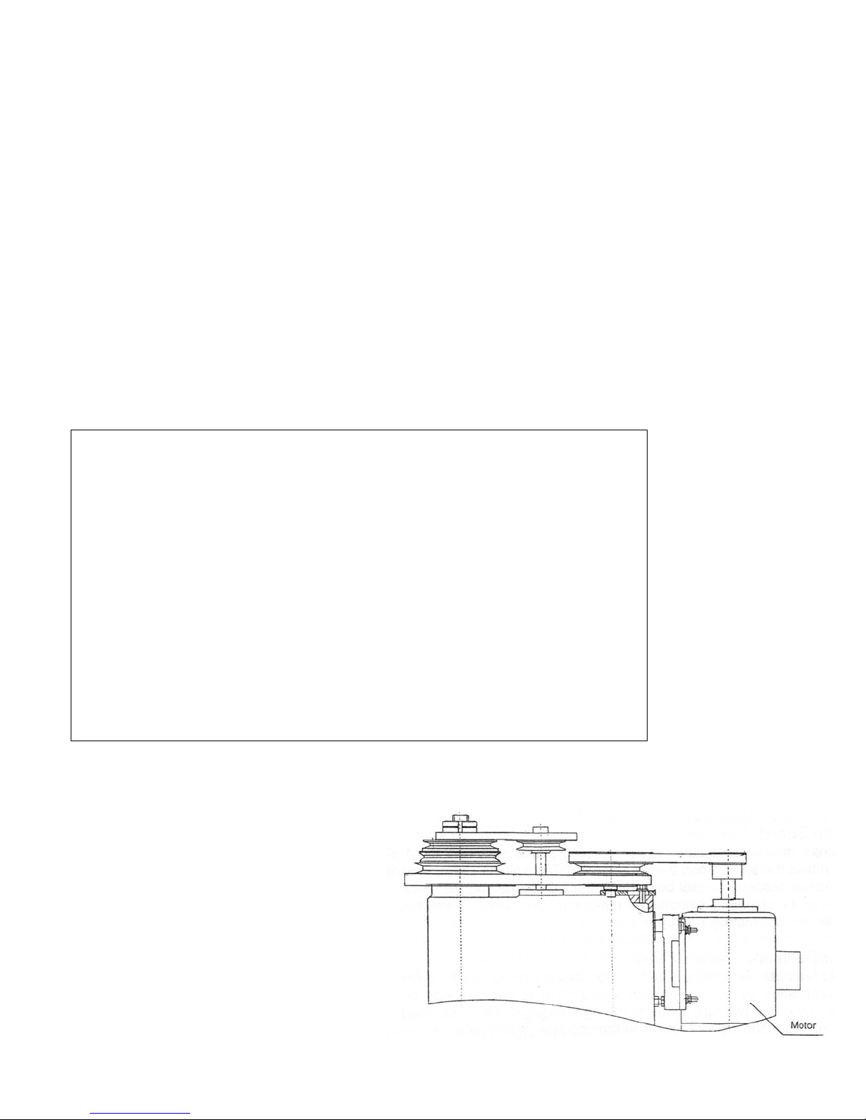
SPEED CHANGE
A quick Speed (Torque) Range change can
be accomplished with the Ellis HI-Lo Handle
on the right side of the machine. (See the
enclosed instruction sheet.) Note: The motor
must rotate at a moderate speed to change the
operating speed range selection. The variable
speed control can vary the speed innitely
within each speed (Torque) range setting
which is explained in the next paragraph.
LOW SPEED HIGH TORQUE OPERATION
It is highlly recommended to shift into low using
the “Ellis High/Low Shift” For big drills, tapping
and hole saws see pages 14 and 15 for more information.
4
 Loading...