

Ellis 6000 Instruction Manual
1-800-383-5547 • EllisSaw.com
EllisSaw.com
1-800-383-5547
P.O. Box 930219 • Verona, WI 53593-0219
GENERAL OPERATING & SAFETY INSTRUCTIONS
* READ INSTRUCTIONS BEFORE USE *
CAUTION: Disconnect power supply cord from power source when doing repair work or changing belt.
To avoid personal injury: Always wear safety glasses or a face shield.
Always wear gloves and protective clothing.
Wear a dust mask or respirator as required.
Wear hearing protection as required.
UNPACKING AND SETUP
First, check machine over for any shipping damage. After the
belt grinder is uncrated, remove any tapes, straps or packing
material from the grinder. A light weight hand truck can be
used to move it around the shop. The motor end should be toward the operator as the grinder is tipped back onto the truck.
SAFETY PRECAUTIONS, FEATURES &
OPERATING INSTRUCTIONS
1. When using the grinder, basic safety precautions should
always be followed to reduce risk of re, electrical shock
and personal injury. Read WARNING section!
2. Use caution, be alert and maintain a balanced stance at all
times while operating the Grinder. The abrasive belt rotates
at 5000 surface feet per minute (SFM) and will cause
serious injury if contacted directly.
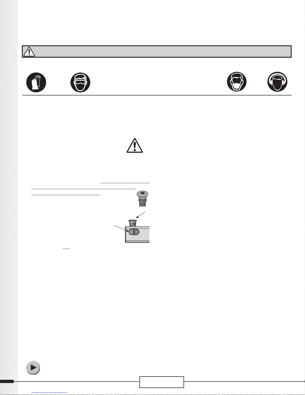
3. The belt grinder is equipped with a red emergency stop button, Item 11 (E-Stop). Push the button
down to stop the grinder. To release it, turn the
button clockwise.
4. The grinder also has an On-O switch, Item
12. Pushing the green button starts
the grinder; pushing the red button stops it.
5. In case of a power outage during operation,
the grinder will not restart when the power
returns. The green button has to be pushed.
6. Always keep children away.
Caution: Once the grinder has been turned o , the belt will still
be in motion until it stops on its own.
START-UP
1. Plug power cord into 115V AC 60 HZ single phase power
receptacle.
2. Check to see that the red emergency stop button is in the
upright position, otherwise turn it clockwise.
3. Check the belt alignment by turning the grinder on and
o quickly. Watch to see that the belt is centered on the
contact wheel. If not, read the next section:
“Belt Tension, Alignment and Adjustment.”
Note: Possible damage could occur to the belt and grinder if
the belt tracks o center.
Visit our website, EllisSaw.com, for
video instruction and more information
2
or contact Ellis for a DVD.
E-Stop
EllisSaw.com
1-800-383-5547
BELT TENSION, ALIGNMENT & ADJUSTMENT
1. The sliding tube assembly, Item 18, must be fully extended
to provide the correct belt tension. Lock the belt release
hand wheel rmly to maintain proper belt tracking.
2. If the belt is tracking o the contact wheel toward the
right, turn the belt alignment knob, Item 17, clockwise
slowly until the belt tracks directly over the contact wheel.
3. If the belt tracks o toward the left, the belt alignment
knob should be turned slowly counter-clockwise to bring
the belt back in alignment.
Note:
When making belt alignment adjustments, the belt
should be in motion.
BELT CHANGE
1. Switch motor o and unplug the grinder. Wait until belt
has stopped moving.
2. Turn the belt release handle, Item 15, counter-clockwise
as you face the hand wheel to unlock the sliding tube assembly, Item 18.
3. Grasp the belt release lever, Item 16, and pull back as far as
the sliding tube assembly, Item 18, is allowed to go. Hold
lever and lock Item 18 in this position by retightening the
belt release hand wheel.
4. Grasp the lower right hand corner of the hinged side cover
and lift it up to rest on the hinge stop. Slide the belt o .
5. Check the new belt carefully. Do not use a belt with a
nicked or cut edge or with handling damage.
6. Use only a 2–1/2” wide belt. A wider or narrower belt could
cause damage to the contact wheel or the belt.
7. Look for an arrow marked on the inside surface of the new
belt. The contact wheel and drive wheel rotate in a counter
clockwise direction. Not all belts have an arrow, but if one
is marked on the belt, the arrow must point in the direction
the belt will be traveling. See Item 2 in the manual which
indicates the direction of the arrow. Center the new belt on
the contact wheel and drive wheel.
8. Close the cover.
9. Hold the belt release lever to keep the sliding tube assembly, Item 18, from jumping forward while releasing it with
the release hand wheel. Allow Item 18 to move forward
as far as it will go. Lock it in position with the release hand
wheel.
10. Check the belt alignment as described in the “Start-up”
section.
WARNING
• Use the grinder in a well ventilated area. The dust
created when grinding some materials can be
harmful. Dust masks are strongly recommended to
minimize dust inhalation.
• Sparks from the grinder could ignite ammable
materials and fumes. Keep these materials at a
safe distance from the grinder.
• Do not remove cover and guards on the machine
while doing grinding operations.
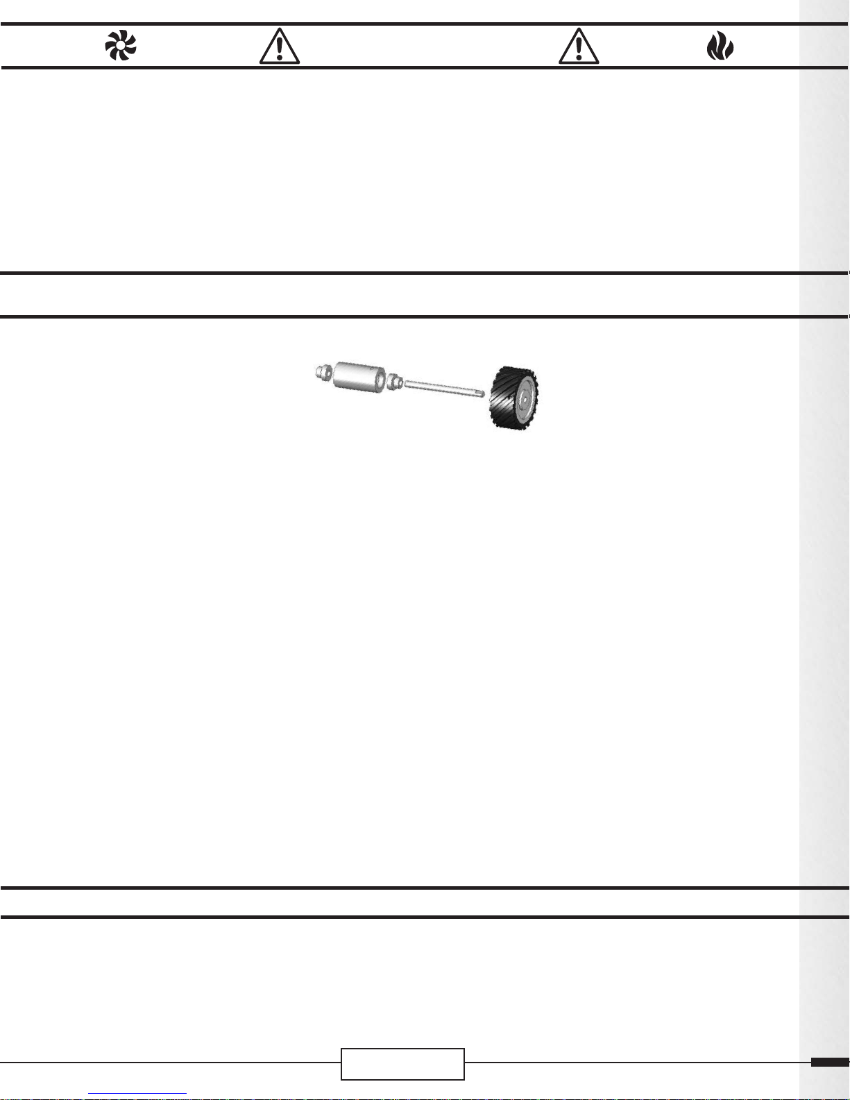
Contact Wheel, Spindle and Bearing Replacement
1. To remove the bearings, rst remove the
contact wheel, Item 26, by loosening
the set screw with a 5/32 inch hex
key wrench. Refer to the parts catalog
illustration.
2. Next remove the socket head cap screw
and the adapter hex bolt, Items 19 & 21, and the
lock washers, Item 20, that secure Item 22 to Item 18.
Use a 5/16 inch hex key wrench. Set these aside for reassembly.
3. Slide the bearing housing assembly out and place on a
work bench.
4. Loosen the set screw on each bearing collar, using a 1/8
inch hex key wrench.
5. Slide the spindle out of the bearing housing. You may
need to twist the collars and tap gently on the end of
the spindle.
6. Remove the old bearings with a punch or similar tool.
Tap the bearing out from the opposite end.
7. When replacing the new bearings use an arbor press or
tap the bearing into the housing with a hammer. Take
care not to damage the bearing. Press or tap only on the
outer ring of the bearing.
8. Slide the spindle into the bearings so that the end at the
rear of the housing is going to be ush with the bearing
collar. If the spindle does not t, remove the burrs on
the spindle with a ne le.
9. Place the collars over the spindle and bearings. Rotate
each collar individually on its bearing in the direction
GRINDING TECHNIQUES
• Check that the drive and contact wheels are running true and are free of damage. Worn or damaged parts should be replaced immediately.
• Check a new belt for nicks or cuts along its edge.
Do not use if damage is evident.
• Use extreme caution when grinding magnesium.
Magnesium dust can ignite. Have a bucket of sand
close by to extinguish a re.
that the belt turns. That is, a counter-clockwise
rotation as you face the contact wheel end
of the spindle. Tighten the set screw us-
ing a 1/8 inch hex key wrench. Then
use a center punch and place it in the
countersunk hole on the collar. Tap
the punch lightly with a hammer so the
collar is “set” in the counter-clockwise motion. Repeat
with the other collar.
10. Replace the bearing housing assembly, Item 22.
a. Place the bearing housing assembly, Item 22,
into the Sliding Tube Assembly, Item 18, and line
up the threaded holes on Item 22 with the holes
in Item 18.
b. Place a lock washer, Item 20, over an adapter hex
bolt, Item 19. Insert the bolt, Item 19, into the
top hole in Item 18. Start the bolt into Item 22,
but only to depth of 1 or 2 threads. Repeat this
procedure for the bottom hole.
c. Turn the top bolt and bottom screw (Items 19
& 20), alternately, equal turns, until the lock
washers are compressed solid. Item 22 should be
centered within Item 18.
11. Replace contact wheel
Place contact wheel, Item 26, on the spindle with the
set screw side on the outside. Tighten the set screw
on the contact wheel hub, using a 5/16 inch hex
wrench.
Hand Held Grinding
All grinding should be done below the centerline of the
contact wheel because it will be easier to hold the work and
minimize chatter. Present the workpiece to the contact wheel
in an upward motion to improve cutting and to draw the
hands away from the abrasive belt.
EllisSaw.com
1-800-383-5547
Platen Grinding
The platen is designed for grinding at surfaces using light
pressure.
Tool Grinding
Use the tool rest, part # 7075, for accurate grinding such as
drill bits, chisels, etc.
3
 Loading...