

Ellis 90H, 1200, 1000, 1440, 1600 Installation And Operating Instructions Manual
...
Motor
Drive Wheel
End
PARTS C ATALOG 2H
M
FG
. C
OMPANY
, I
NC
.
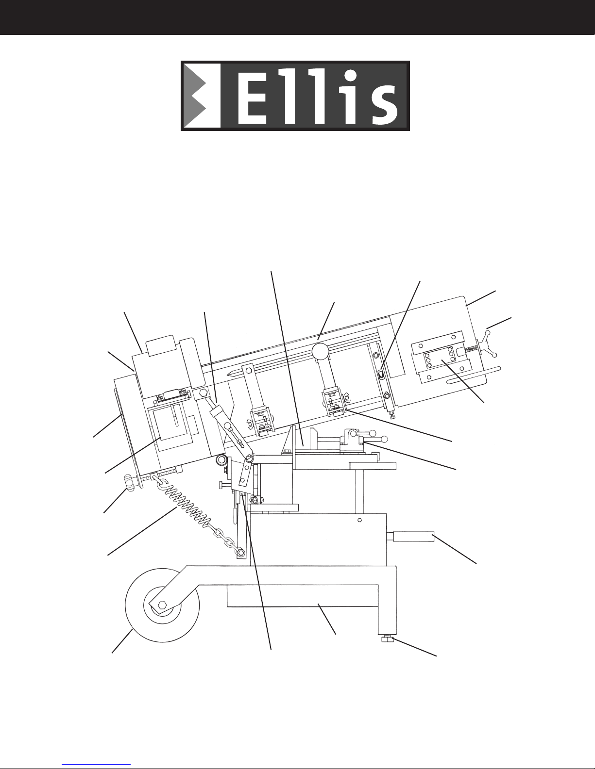
Mitre Band Saw
Installation and Operating Instructions
Note: Not all saw parts are shown in this booklet
Replaceable Aluminum Saw Table
Automatic Shut-Off Switch
Hydraulic Feed
Control
Moveable Guide Arm
Idler Wheel End
T-Handle
Blade Tension
Adjustment
Pulley Box
Speed
Reducer
Head Weight
Adjustment
Compensating
Spring Assembly
Cart Wheel
Bearing Carrier Assembly
Idler Spindle
Adjusting Plate
Blade Guide
Assembly-Idler
Vise
Telescoping Handle
with Grip
Chip Tray
Adjustable Legs
107 W. Railroad Street • P.O. Box 930219 • Verona, WI 53593-0219
Phone: (608) 845-6472 • Fax: (608) 845-5199 • www.ellissaw.com
1-800-383-5547
PARTS CATALOG
Page 2
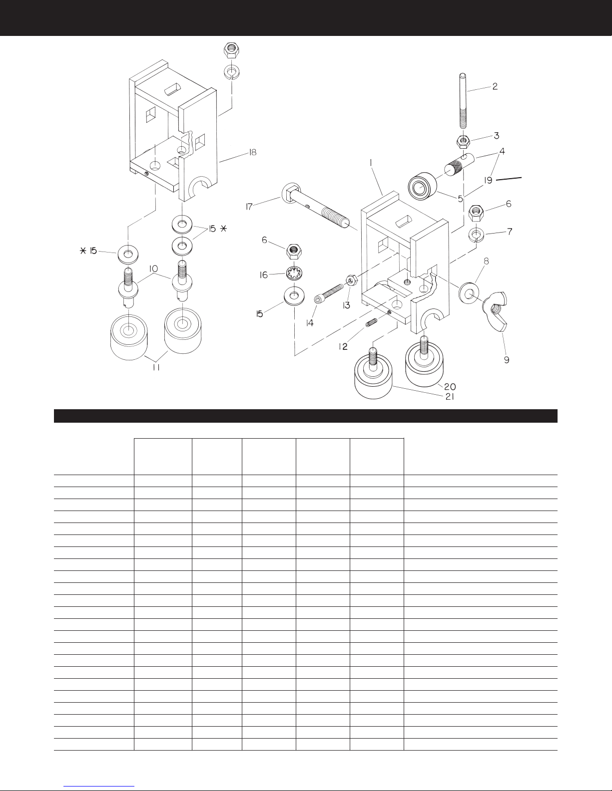
B LADE G UIDE
Complete
Assembly
Bearing Only
90H
Item No. Description
Complete Assy. 9016DC 5370 5539 5720 5732 Blade Guide Assembly, Drive End
Complete Assy. 9016IC 5371 5519 5721 5733 Blade Guide Assembly, Idler End
1 9016I 5391 5588 5588 5981 Housing Assembly, Idler
2 5541 5541 5541 5541 5541 Adjustment Stud, Bearing Plate
3 4260 4260 4260 4260 4260 1/4-20 Hex. Nut
4 6066 6066 6066 6066 5999 Spindle, Pressure Bearing
5 4499 4499 4499 4499 4522 Ball Bearing, Pressure
6 4260 4260 4266 4266 4279 Nut, Hex.
7 4336 4336 4337 4337 4343 Lock Washer, Spring
8 4310 4310 4310 4310 4311 Flat Washer, SAE
9 4271 4271 4271 4271 4270 Wing Nut or Stop Nut
10 5389 5389 5587 6074 6073 Spindle, Guide Bearing
11 4522 4522 4502 4502 4515 Ball Bearing, Guide
12 4140 4140 4140 4140 8-32 x 3/8 Set Screw
13 4258 4258 4258 4258 4260 Hex. Nut
14 4155 4155 4155 4155 4137 Socket Head Cap Screw
15 4304 Flat Washer, 3/16 or 1/4 Std.
16 4355 4355 4356 4356 4343 Lock Washer
17 5374 5374 5542 5542 6056 Guide Clamping Bolt
18 9016D 5390 5540 5540 5982 Housing Assembly, Drive
19 9012 9012 9012 9012 5996 Pressure Bearing Assembly
20 5406 5406 6730 6742 6747 Stationary Guide Bearing Kit
21 5407 5407 6732 6743 6747 Adjustable Guide Bearing Kit
*On all saws, except for the Model 4000, the stationary and adjustable kits are the same except for items 6, 16, and 15 which are included with
the adjustable kits. On the Model 4000 there is no adjustable kit. Therefore, use part number 6747 for both bearing kits on the Model 4000.
1100
Blade Guide Assembly
Part Number For Models
900
1000
1200
1440
1500
Complete
Assembly
1600
1800
2000
3000 4000
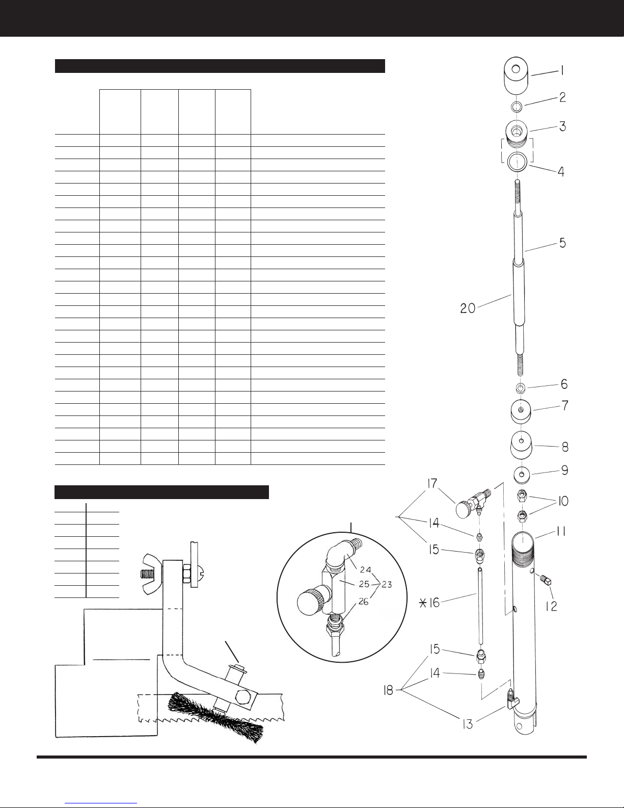
H YDRAULIC F EED C ONTROL
Hydraulic Feed Control Assembly
Part Number For Models
90H
900
1000
Item No. Description
Assy. 5355 5506 5708 5777 Hydraulic Feed Control Assembly
1 5529 5529 5529 5529 Cap
2 4950 4950 4950 4950 O-Ring-Shaft
3 5532 5532 5532 5532 Sealing Washer, Top
4 4951 4951 4951 4951 O-Ring-Cylinder
5 5361 5530 5530 5766 Shaft
6 4337 4337 4337 4337 Lock Washer, 5/16
7 5531 5531 5531 5531 Sealing Washer, Bottom
8 5533 5533 5533 5533 Leather Cup
9 5534 5534 5534 5534 Washer-Special
10 4266 4266 4266 4266 Nut, Hex. Jam, 5/16-24
11 5362 5528 5528 5767 Cylinder
12 4743 4743 4743 4743 Plug, Oil Fill
13 4730 4730 4730 4730 Male Elbow - Tube Fitting
14 4732 4732 4732 4732 Sleeve
15 4729 4729 4729 4729 Nut
16 5363 5590 5711 5706 Tube, 1/4 Dia. Plastic
17 4731 4731 Needle Valve-Tube Fitting
18 4728 4728 4728 4728 Male Elbow Assembly
19* 4727 4727 Needle Valve Assembly
20 5356 5749 5749 5748 Travel Stop Tube
21 6702 6702 6702 6702 Rebuilding Kit
22 5707 5707 Remote Needle Valve Assembly
23* 4808 4808 Flow Needle Valve Assembly
24 4735 4735 Elbow, Male to Male
25 4734 4734 Flow Needle Valve
26 4736 4736 Straight Fitting
*19 and 23 are interchangeable.
1100
1200
1500
1600
1800
1440
2000
3000
4000
Page 3
Saw Pivot Arm Assembly
1100 5393
1200 5393
1500 5685
1600 6350
1800 6366
2000 6350
3000 6366
4000 6366
Chip Brush Assembly
Part No. 5550
Ellis Mfg. Company, Inc. 107 W. Railroad Street • P.O. Box 930219 • Verona, WI 53593-0219
Phone: (608) 845-6472 • Fax: (608) 845-5199 • www.ellissaw.com
23 or 19
 Loading...