

ElliptiGO 8S, C-Series, 11R, Arc Owner's Manual

Owner’s Manual

Owner’s Manual
Welcome to the ElliptiGO® Family,
Thank you for purchasing an ElliptiGO bicycle. We have spent countless hours developing this fitness device and believe
it to be the best form of low-impact exercise available. We hope you enjoy many years of healthy exercise and fun while
riding it.
As you will see throughout this owner’s manual, we value your safety. We have designed your bike to be a safe, fun
and eective workout system. However, it is not a toy. Your ElliptiGO bike is an advanced piece of fitness equipment
designed to be used for exercise by responsible riders. Improper use of this tool can result in destruction of property,
serious injury, maiming, or death. For your safety, before your first ride you should read the entire owner’s manual and
pay particular attention to Chapters 2 and 3. This information is essential for understanding how to safely use and enjoy
your machine. Although many of the components may look familiar to you, an ElliptiGO bike is very dierent from any
other piece of fitness equipment or vehicle you may have used in the past. As a result, it is VERY IMPORTANT that you
read and understand the information in this manual before riding it. Doing so could save your life.
In addition, we have safety and maintenance videos and information posted in the customer section of our website at
www.elliptigo.com/support.html. If you have any questions or concerns, especially about how to safely use your ElliptiGO
product, please contact us at any time at service@elliptigo.com.
Happy riding,
Brent and Bryan
ElliptiGO Co-Founders

Owner’s Manual
CHAPTER 1: IMPORTANT NOTIFICATIONS
CHAPTER 2: PRODUCT FAMILIARIZATION
General Overview
Terminology and Component Overview
Proper Handling & Carrying Procedure
Kickstand Operation
Quick Release Clamping Systems
Steering Columns
Brakes
Gearing Systems
Chain Tension
Wheels, Tires and Tubes
Chain Keeper
CHAPTER 3: RIDING
Basic Cycling Safety
Adjusting the Fit
Pre-Ride Safety Checklist
Familiarization Ride
Normal Riding
Climbing and Descending Hills
Riding in Adverse Conditions
Competitive and Group Riding
Stationary Trainers
CHAPTER 4: SERVICE AND MAINTENANCE
Servicing ElliptiGO Products
Maintenance Chart
What Happens if I Damage My ElliptiGO Cycle?
How Long Will My Bike Last?
Torque Requirements for Screws
and Fasteners
Satisfaction Guarantee and
Limited Warranty
IMPORTANT:
This owner’s manual contains information regarding your components and how to do basic maintenance and service
on your ElliptiGO® cycle. However, it is not intended to be a substitute for having your product serviced by a professional
bicycle mechanic. YOU SHOULD HAVE YOUR ELLIPTIGO BIKE ASSEMBLED, MAINTAINED AND SERVICED BY A
PROFESSIONAL BICYCLE MECHANIC.
Table of Contents

Owner’s Manual
CHAPTER 1: Important Notifications
DO NOT SKIP THIS SECTION!
Like running and cycling, riding an ElliptiGO® elliptical
bicycle involves a real risk of serious injury, maiming and
death. Each time you ride your ElliptiGO cycle, you are
assuming this risk. We cannot stress enough how important
it is to wear a helmet and proper clothing, know and follow
the rules of the road, ensure your bike is in good working
order before and during your ride, and to use caution when
riding. To help minimize your risk of injury when riding your
elliptical bicycle it is critical that you read and understand
the contents of this manual and become familiar with
operating and maintaining your bike before you head out
on the road.*
To highlight some of the most important safety concerns,
this manual contains many “Warnings”, “Cautions” and
“Alerts” which are set out conspicuously in the manual.
Safety Warning
The following symbol: WARNING! (the safety designator
together with the word WARNING!), calls attention to a
potential hazard that, if not properly addressed or avoided,
could cause serious injury or death.
Safety Caution
The following symbol: CAUTION! (the safety designator
together with the word CAUTION!), calls attention to a
potential hazard that, if not properly addressed or avoided,
could cause property damage or an injury.
Damage Alert
The designation ALERT! calls attention to a situation
which, if not properly addressed or avoided, could cause
serious damage to your ElliptiGO bike and/or void your
warranty.
As you will see, most of the Safety Warnings and Cautions
contained in this manual relate to conditions that could
result in the rider losing control of the ElliptiGO bike and
suering a fall. Every fall, regardless of the associated
speed or cause, can result in serious injury or death for the
rider, and injury to bystanders and property. As a result, a
warning that indicates the rider may lose control and fall if
a situation is not properly addressed or avoided may not
also state that the resulting fall can cause serious injury
or death. You should understand that this fact is always
implied by the possibility of falling.
* No manual can address all of the potentially hazardous
situations that could arise when riding a bike. As a result,
we cannot provide guidance on how to safely ride the
ElliptiGO bike in every circumstance. There are many
unpredictable and unavoidable risks that are inherent
in the sport of cycling. By choosing to ride a bike, you
are voluntarily exposing yourself to these risks and are
responsible for that choice.

Owner’s Manual
CHAPTER 2: Product Familiarization
General Overview
The ElliptiGO® elliptical bicycle is a completely new kind
of exercise device and performs dierently from other
machines you may have used in the past. If you treat it
with respect, keep it maintained, and use it as intended,
your ElliptiGO bike should provide you with many years
of enjoyable outdoor exercise. Before your first ride, you
should read this manual in its entirety and get clarity on
all aspects of the bike’s performance, function, or design
that you do not understand. You should also consult
your physician prior to beginning any exercise plan,
including exercising on your ElliptiGO bike, to ensure that
you are healthy enough for such exercise. You can reach
our customer service department to get any questions
answered by sending an email to: service@elliptigo.com.
Intended Use
ElliptiGO bikes are intended to be used on paved surfaces
by individuals weighing less than 250 pounds
for the purpose of enjoying outdoor exercise.
The use of an ElliptiGO elliptical cycle in any other manner
is improper and falls outside of the scope of what the
product was designed to do.
WARNING! ELLIPTIGO ELLIPTICAL BICYCLES ARE
NOT TOYS AND ARE NOT DESIGNED FOR USE BY
CHILDREN. The ElliptiGO bike does not meet the safety
requirements for use by children, nor is it configured
for use by children. Because it lacks the safety features
required for children’s products, children can be
seriously injured or killed while using the ElliptiGO
bike. Consequently, DO NOT LET CHILDREN USE YOUR
ElliptiGO BIKE. If you purchased your ElliptiGO product
for a minor child, please contact ElliptiGO Inc. for a full
refund immediately.
For use on Paved Surfaces
Our products have been optimized for riding on paved
surfaces and there are certain aspects of our elliptical
cycles that pose a risk to the rider if they are ridden
“o-road” or on unpaved surfaces (including gravel, sand,
or dirt). For example, the ElliptiGO bike’s tires are not
designed to be taken onto surfaces other than paved
roads and will have degraded stopping and maneuvering
abilities in those conditions. Similarly, for bikes with guide
track systems, those systems must be kept free from debris
to function properly. Riding on unpaved roads drastically
increases the likelihood of getting debris into the track
system which can damage the track system or cause the
rider to lose control and suer a fall. As a result, riding
on unpaved roads falls outside the intended use of the
ElliptiGO and could void your warranty.
Weight Restrictions
ElliptiGO bikes have a gross weight limit of 250 pounds for
the rider and all accessories. By limiting the gross weight
of the rider and accessories to 250 pounds combined, we
have been able to create an aordable exercise device
that delivers a high-performance fitness experience. This
II

Owner’s Manual
weight limit was relied upon for every aspect of the design,
from the components we selected, to the frame materials
and configuration, to the thickness of the drive arms and
steering column. Riders weighing more than 250 pounds
fully-laden can subject the elliptical cycle to loads that
exceed those to which we have tested our products. This
could result in catastrophic failure of key components
during regular riding.
In addition, even if the product does not appear to be
damaged by a rider who weighs more than 250 pounds,
the fatigue and stress caused by such a rider could greatly
diminish the lifespan of many of the components we use.
As a result, allowing your elliptical bike to be ridden by
someone who exceeds 250 pounds voids your warranty
and could result in a catastrophic failure of one or more
components causing a rider to suer a fall and be injured.
The Purpose of an ElliptiGO Elliptical Cycle
The purpose of an ElliptiGO elliptical cycle is to deliver a
fun, low-impact, outdoor exercise experience. It is not to be
used for trick riding and should never be used for stunts,
jumps, wheelies, or other abusive maneuvers.
These will dramatically reduce its service life and
could cause a catastrophic failure of one or more of its
components, causing the rider to suer significant injuries
or death from a resulting fall.
WARNING! THE ELLIPTIGO BIKE HAS REAL
LIMITATIONS IN WHAT IT CAN SUSTAIN. Misusing the
bike can be extremely dangerous and void your warranty.
Improper use of the bike, including riding with a combined
rider and accessories weight that exceeds 250 pounds or
stunt, trick, or o-road riding, can cause a catastrophic
failure of one or more components and result in the rider
suering a serious injury or being killed. DO NOT ENGAGE
IN THESE OR OTHER ABUSIVE ACTIVITIES.
Owner’s Manual
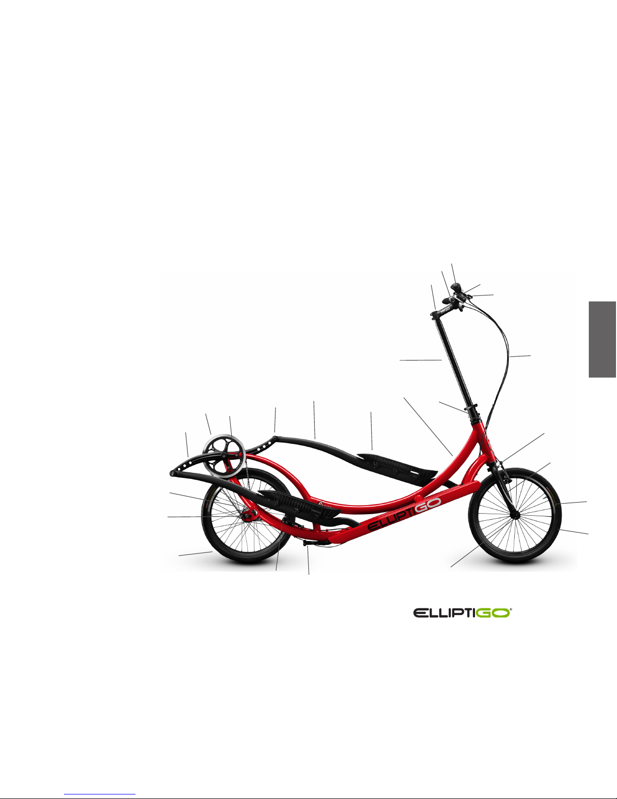
The picture below gives an overview of the components which make up the
ElliptiGO® 3C and 8C products. These names will be referred to throughout the
owner’s manual.
Terminology & Component Overview
3C and 8C Models
1 FRAME
2 PRELOAD COLLAR
3 STEERING COLUMN
4 STEM
5 SHIFTER
6 GRIP
7 HANDLEBAR
8 BRAKE LEVERS
9 CONTROL CABLES
10 FRONT BRAKES
11 FORK
12 FRONT WHEEL
13 TIRE
14 FRONT QUICK RELEASE
15 KICKSTAND
16 REAR BRAKE
17 REAR WHEEL
18 INTERNALLY GEARED HUB
19 CHAIN
20 CRANK ARM
21 CHAINRING GUARD
22 CHAINRING
23 DRIVE ARM AXLE
24 DRIVE ARM
25 FOOT PLATFORM
II
1
24
25
15
23
20
22
21
17
12
13
14
11
10
3
4
5
6
7
8
9
2
18
19
16
Owner’s Manual
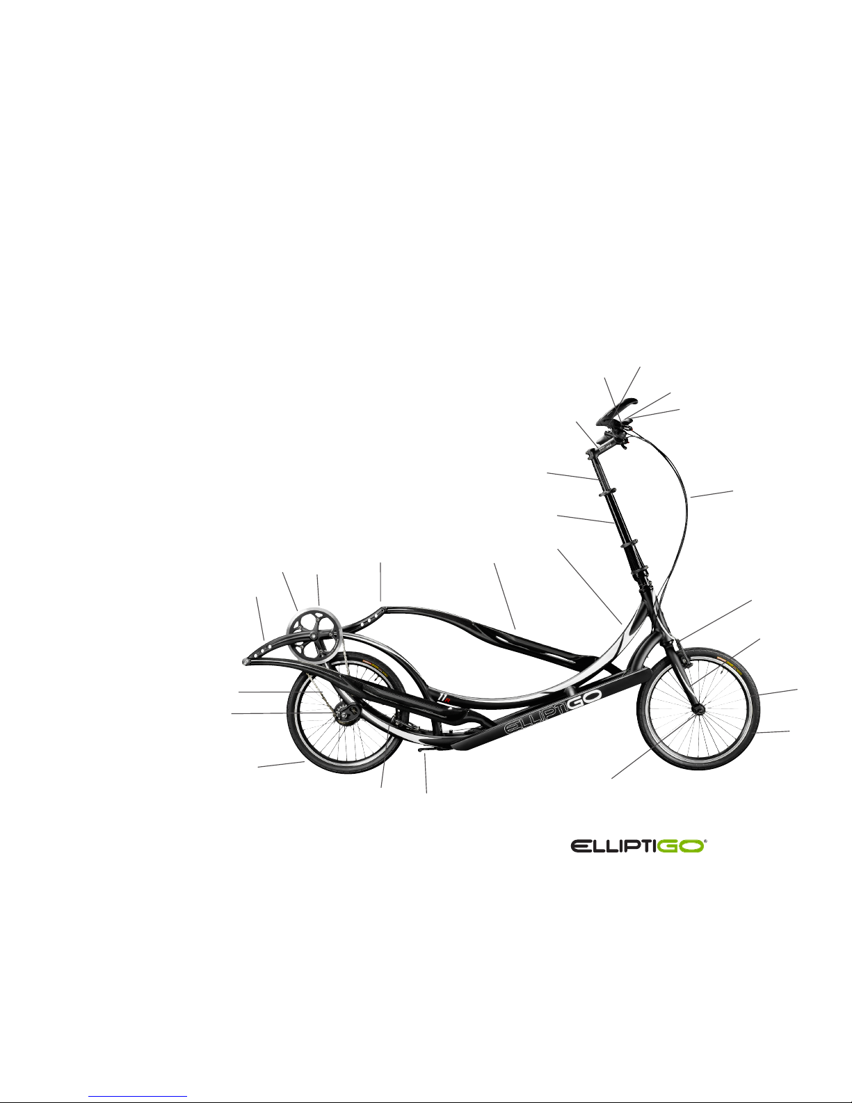
1 FRAME
2 FOLDING STEERING COLUMN
3 STEERING EXTENDER
4 STEM
5 SHIFTER
6 GRIP
7 HANDLEBAR
8 BRAKE LEVERS
9 CONTROL CABLES
10 FRONT BRAKES
11 FORK
12 FRONT WHEEL
13 TIRE
14 FRONT QUICK RELEASE
15 KICKSTAND
16 REAR BRAKE
17 REAR WHEEL
18 INTERNALLY GEARED HUB
19 CHAIN
20 CRANK ARM
21 CHAINRING GUARD
22 CHAINRING
23 DRIVE ARM AXLE
24 DRIVE ARM
1
24
23
20
22
21
19
17
12
13
14
11
10
2
3
5
4
6
7
8
9
18
16
The picture below gives an overview of the components which make up the
ElliptiGO® 8S and 11R models. These names will be referred to throughout the
owner’s manual.
Terminology & Component Overview
8S and 11R Models
15
Owner’s Manual
1
24
26
28
27
29
25
22
23
14
15
16
17
18
13
20
19
12
3
2
4
6
7
8
9
10
11
5
21
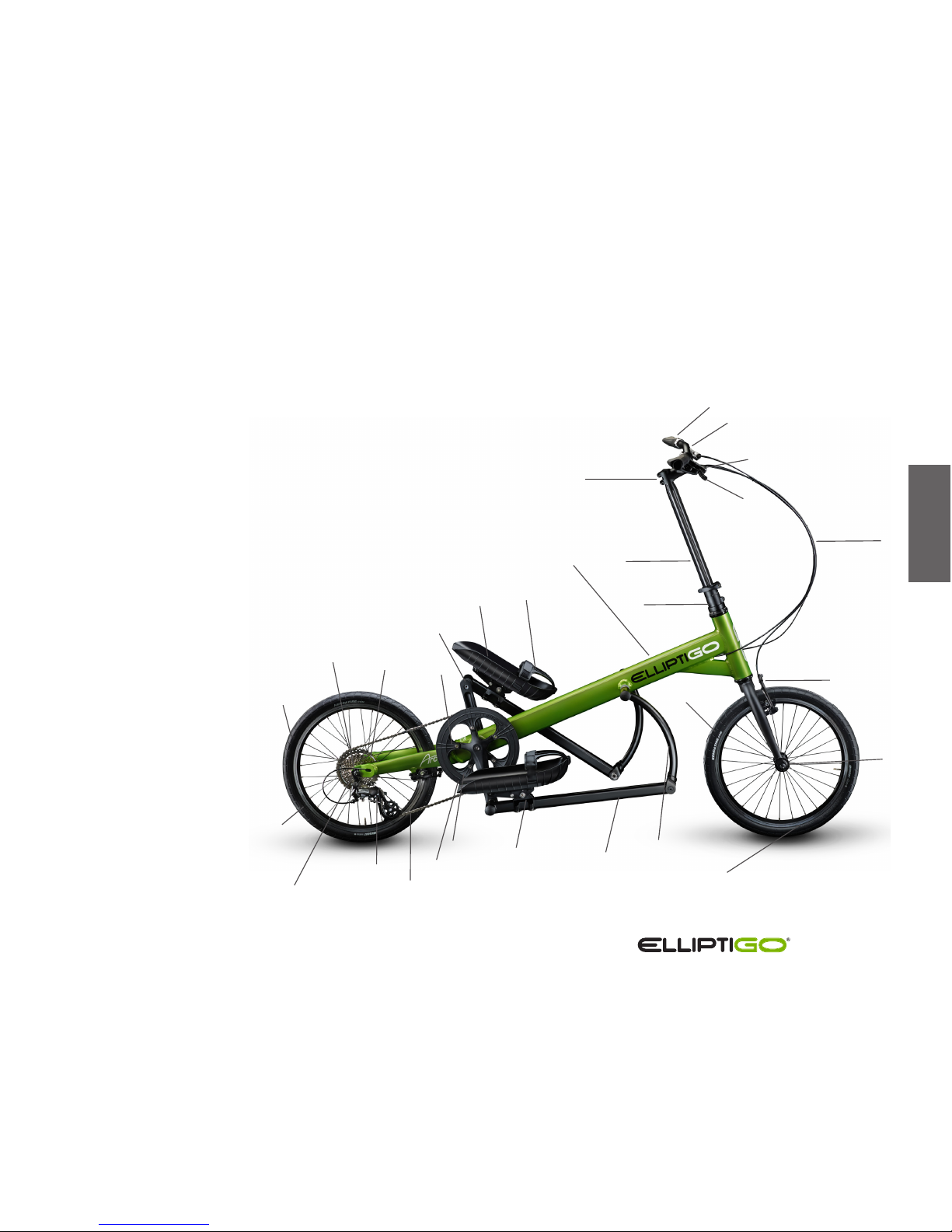
The picture below gives an overview of the components which make up the
ElliptiGO Arc product. These names will be referred to throughout the
owner’s manual.
Terminology & Component Overview
ElliptiGO Arc Model
II
26 CHAIN KEEPER
27 CRANK ARM
28 FOOT PLATFORM
29 TOE CAGE (OPTIONAL ACCESSORY)
1 FRAME
2 PRELOAD COLLAR
3 STEERING EXTENDER
4 STEM
5 GRIP
6 HANDLEBAR
7 SHIFTER
8 BRAKE LEVERS
9 CONTROL CABLES
10 FRONT BRAKE
11 FRONT WHEEL QUICK RELEASE
12 FRONT WHEEL
13 TIRE
14 SWING ARM
15 DRIVE ARM
16 FOOT PLATFORM ASSEMBLY
17 CHAINRING GUARD
18 CHAINRING
19 CHAIN
20 REAR DERAILLEUR
21 CASSETTE
22 REAR WHEEL
23 REAR TIRE
24 REAR QUICK RELEASE
25 KICKSTAND (HIDDEN)
Owner’s Manual
Proper Handling and Carrying Procedure
C-Series and Models 8S and 11R
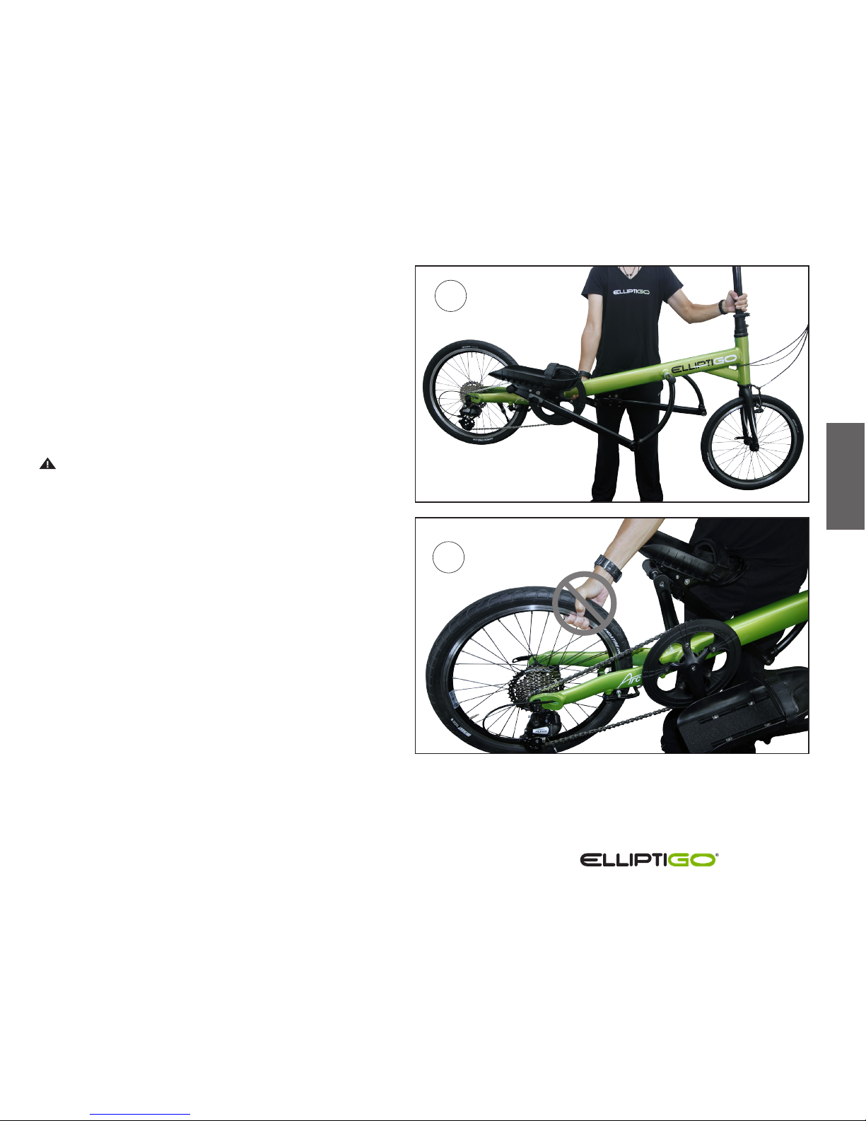
Picture 1 to the right demonstrates the proper method
for handling, lifting or carrying your ElliptiGO® C-Series,
8S or 11R elliptical bike. The machine should be handled
with one hand on the frame member which goes over
the top of the rear wheel and the other hand on the
steering column.
Picture 2 demonstrates an improper handling method
which could result in bodily injury to the user.
CAUTION! The ElliptiGO bike should never be picked
up by any of the moving mechanism components such
as the drive arms, crank arms, chain, chain ring or rear
wheel. Doing so could cause your hand, wrist or arm
to get pinched by the mechanism potentially causing a
significant injury.
1
2
Owner’s Manual
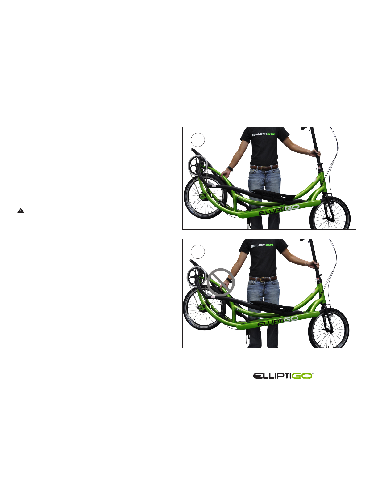
ElliptiGO® Arc Handling
Picture 1 to the right demonstrates the proper
method for handling, lifting or carrying your
ElliptiGO Arc. The machine should be handled with
one hand on the frame and the other hand on the
steering column.
Picture 2 demonstrates an improper handling
method which could result in bodily injury to the
user.
CAUTION! The ElliptiGO bike should never
be picked up by any of the moving mechanism
components such as the drive arms, crank arms,
chain, chain ring or rear wheel. Doing so could
cause your hand, wrist or arm to get pinched by the
mechanism potentially causing a significant injury.
II
1
2
Owner’s Manual
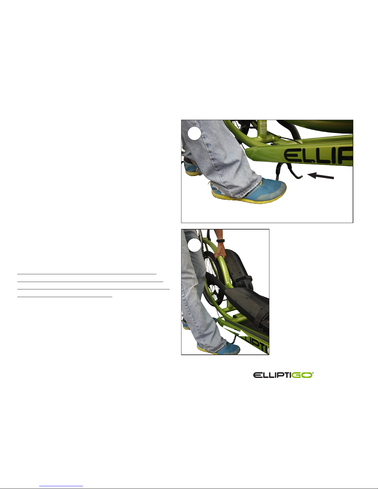
Kickstand Operation
C-Series and Models 8S and 11R
These ElliptiGO® products are equipped with a very
stable double leg kickstand. To operate the kickstand,
follow these steps:
1. Retracting the Kickstand - To retract the
kickstand grab the steering column with one hand
and the frame member which goes over the
top of the wheel with the other hand. Lift
the back of the frame while kicking the kickstand in
the rearward direction.
2. Extending the Kickstand - To extend the
kickstand grab the steering column with one
hand and the frame member which goes over the
top of the wheel with the other hand. Lift the back
of the frame while kicking the kickstand in the
forward direction.
ALERT! Do not stand on bike with the kickstand
extended. Standing on the bike with the kickstand
extended can cause a fall or damage your frame and
kickstand, voiding your warranty.
1
2

Owner’s Manual
ElliptiGO® Arc Kickstand
The ElliptiGO Arc is equipped with a single-leg
kickstand. To operate the kickstand, follow these steps:
1. Retracting the Kickstand - To retract the
kickstand, stand on the side closest to the
kickstand. Grab the steering column with
one hand and lean the bike away from you
so that the kickstand no longer touches the
ground. Then sweep the kickstand backwards
with your foot, ensuring that it fully seats into
the riding position, approximately horizontal with
the ground.
2. Extending the Kickstand - To extend the
kickstand, stand on the side closest to the
kickstand. Grab the steering column with one
hand, lean the bike slightly away from you and kick
the kickstand down and forward.
ALERT! Do not stand on bike with the kickstand
extended. Standing on the bike with the kickstand
extended can cause a fall or damage your frame and
kickstand, voiding your warranty.
II
1
2
Owner’s Manual
Quick Release Clamping Systems
Your ElliptiGO® elliptical cycle comes equipped with quick
release clamping systems on the front wheel, the steering
column and, on some models, the rear wheel. These are
critical parts of any elliptical cycle and riding with an
improperly adjusted quick release is very dangerous. You
must understand how to use the quick release systems
correctly to be able to operate your bike safely.
Quick release clamping systems can generate a significant
amount of clamping force when used correctly. This force
is needed to keep your wheels attached to the frame and
your steering column locked in place while riding. If a
wheel detaches or your steering column collapses while
riding you will likely fall and suer a serious injury.
Each quick release clamping system has three parts – a
lever on one end, a nut on the other end, and a skewer in
the middle. If properly adjusted, closing the lever generates
a clamping force by pushing against the surface closest to
the lever while simultaneously pulling against the surface
nearest the nut. The lever has a cam-action system which
can generate significantly more clamping force than using
the lever or nut in a screw-like fashion can. The ideal
clamping force for a quick release system on a bicycle is
more than a typical person can generate using the lever
as a screw, so it is important that you use the cam-action
lever to operate all quick release systems.
WARNING! An improperly adjusted quick release lever
can allow the steering extender to unexpectedly collapse
or be removed from the bike or enable a wheel to become
loose or detach from the bike. Any of these situations
could cause the rider to lose control of the elliptical cycle
and suer a serious injury or be killed. IT IS CRITICAL
THAT YOU UNDERSTAND HOW TO OPERATE THE QUICK
RELEASE LEVERS AND THAT YOU CHECK THE SECURITY
OF ALL QUICK RELEASE LEVERS BEFORE EVERY RIDE.
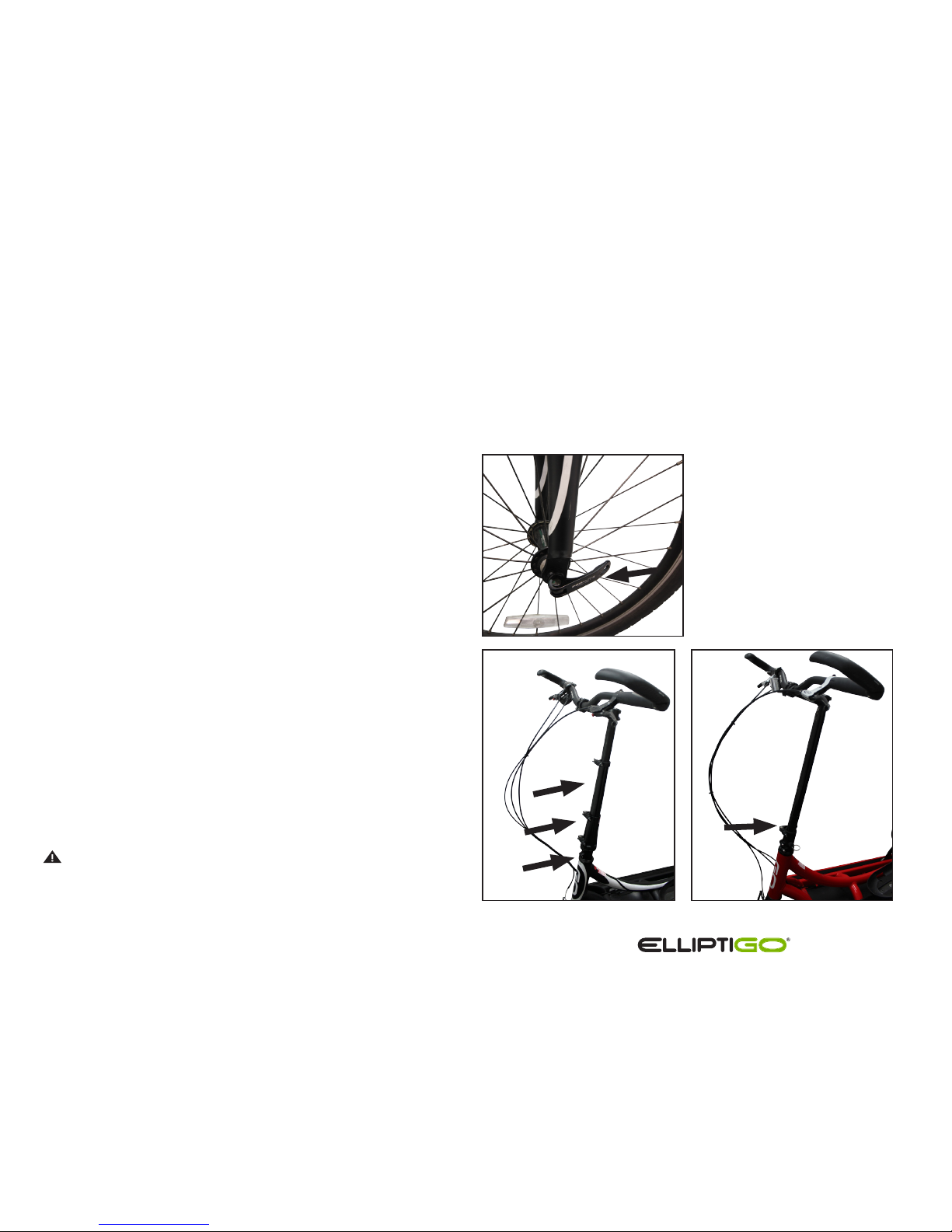
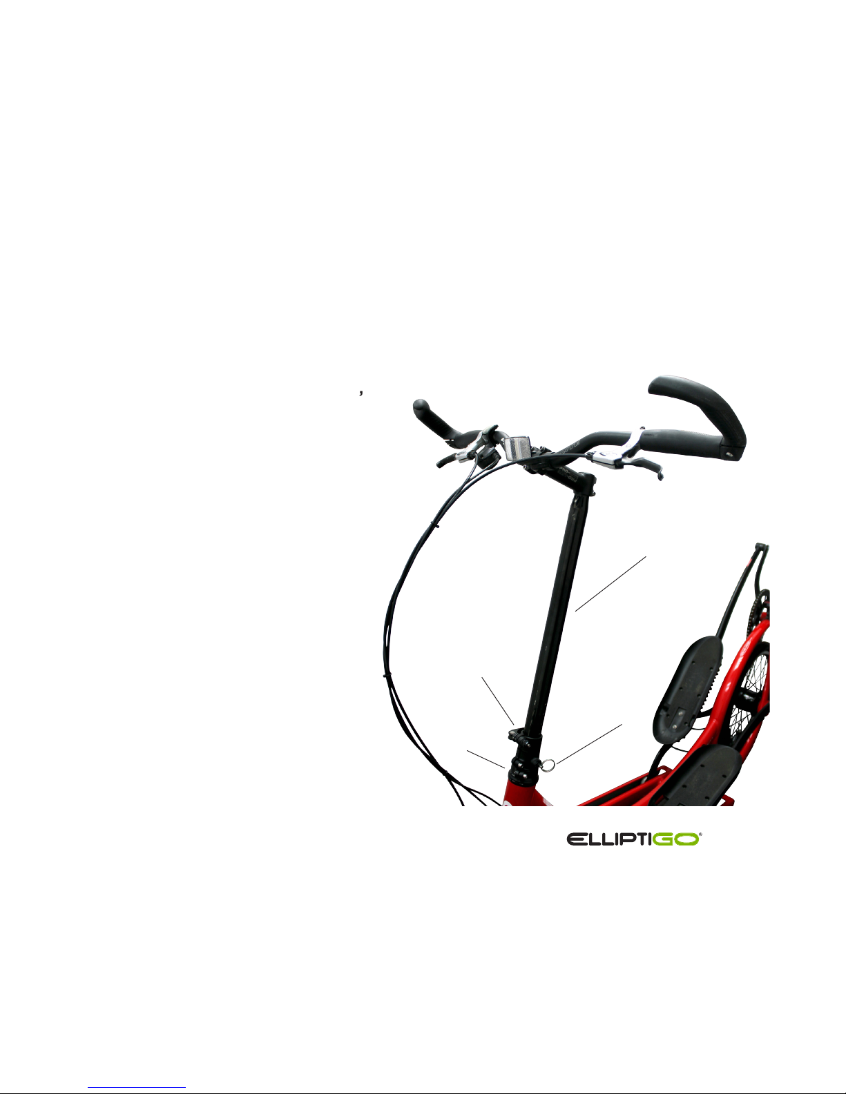
Left: Location of quick
release lever on front wheel.
Below: Locations of quick
release levers on steering
columns.
Owner’s Manual
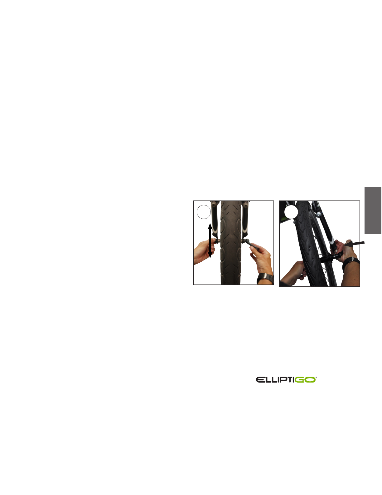
Adjusting the Quick Release Mechanism
The amount of clamping force for the quick release is
controlled by the tension nut.
To increase the clamping force, turn the tension nut
clockwise while holding cam lever fixed with the other
hand.
To decrease clamping force, turn the tension nut
counter-clockwise while holding cam lever fixed with the
other hand.
A QUARTER TURN OF THE TENSION ADJUSTING
NUT CAN MEAN THE DIFFERENCE BETWEEN A SAFE
CLAMPING FORCE AND AN UNSAFE CLAMPING FORCE.
To check the clamping force, attempt to close the quick
release lever. If you can close the quick release lever
completely without using the fork, frame, or steering
extender for leverage, and the lever closes without leaving
a visible impression in your hand, then the quick release
does not have enough clamping force. If, while using one
hand on the fork, steering extender or frame for leverage,
you cannot completely close the lever with the other hand,
then the quick release has too much clamping force.
If there is too little clamping force, tighten the nut
one-quarter turn and try clamping again. Repeat this
until closing the lever requires grabbing the fork, frame or
steering extender and leaves a mark in your hand. If there
is too much clamping force, loosen the nut one-quarter
turn and try clamping again. Repeat this until closing the
lever requires grabbing the fork, frame or steering
extender and the lever leaves a clear mark in your hand.
2
1
II
Owner’s Manual
Steering Columns
C-Series and Arc models come equipped with a non-folding
steering column. 8S and 11R models come equipped with a
folding steering column. All steering columns have a storage
position and a riding position that can be adjusted vertically to
accommodate a wide range of riders.
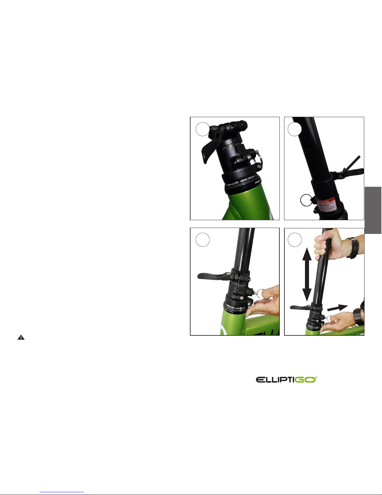
Non-Folding Steering Column – Models 3C,
8C and Arc Model
The non-folding steering column consists of the
following components:
1. The base
2. The steering extender quick release
3. The safety index pin
4. The steering extender
4
3
2
1
Owner’s Manual
The Riding Position
When in the riding position, the steering extender is
inserted to the correct depth in the base, the safety pin is
fully inserted into the selected hole and the quick release
lever is firmly closed. The correct depth is reached when
the handlebar height is the most comfortable for the rider
when riding and the “MAX EXTENSION” line is not visible
above the base. This height is usually set so that the rider
stands tall when riding with little to no weight on his/her
hands or wrists.
To place the non-folding steering column into the riding
position, follow these steps:
1. Place the bike on the kickstand.
2. Open the steering extender quick release.
3. Line up the safety groove on the side of the steering
extender with the notch in the base and ensure that the
control cables are in front of the steering column and
not twisted around the steering extender.
4. Insert the steering extender into the base until it gently
seats against the safety index pin.
5. Pull out the safety index pin with one hand and hold
it while further inserting the steering extender into
the base under until the desired handlebar height is
reached. Ensure that the “MAX EXTENSION” line on the
steering extender is not visible above the base.
WARNING! ENSURE THAT THE “MAX EXTENSION” LINE
ON THE STEERING EXTENDER IS BELOW THE TOP OF THE
BASE! Riding while the “MAX EXTENSION” line is above the
base could result in the steering extender breaking during
operation or being pulled out of the base, causing a fall.
Never use an ElliptiGO product with the “MAX EXTENSION”
line visible above the base.
4
2
3
5
II
Owner’s Manual
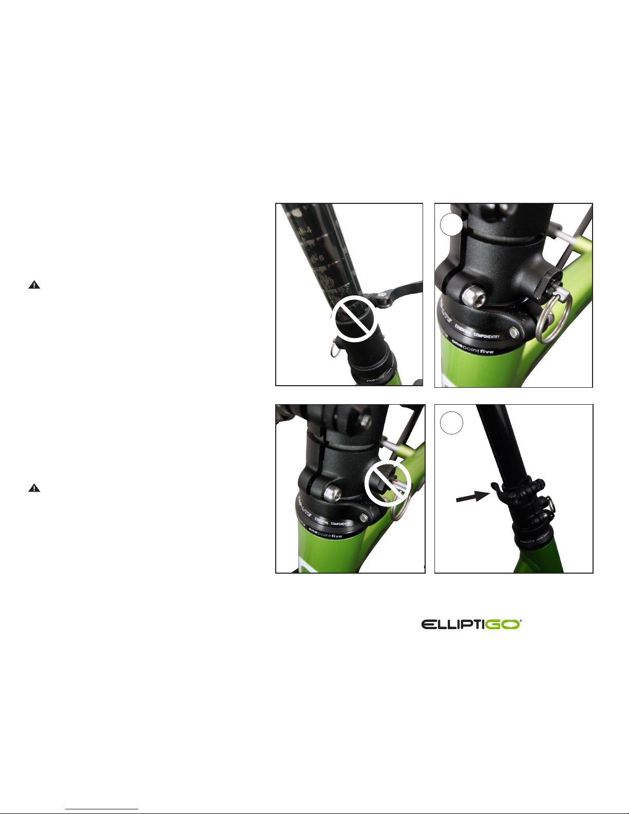
6. Release the safety index pin and make fine
movements on the steering extender until
the pin aligns with the correct hole on the
steering extender and springs completely
back into place. Ensure that no red marks are
visible on the pin.
WARNING! THE SAFETY INDEX PIN
SHOULD BE FULLY SEATED SO THAT NO RED
MARKINGS ARE VISIBLE ONCE THE STEERING
HEIGHT IS SET. Failure to fully seat the
index pin could result in the steering column
collapsing during operation. This would likely
cause the rider to lose control and fall.
7. Secure the steering extender quick
release lever by grasping the steering
extender for leverage and using enough
force to leave an impression on your hand.
See the Quick Release Clamping
System section for details on closing quick
release levers.
WARNING! Securing the quick release
properly is critically important. Failure to do so
could result in the steering extender collapsing
or being removed unexpectedly while riding,
causing the rider to fall. Make sure to follow
the instructions set out in the Quick Release
Clamping Systems section when closing a quick
release lever.
6
7
NO! Do not
exceed MAX
EXTENSION
line!
Owner’s Manual
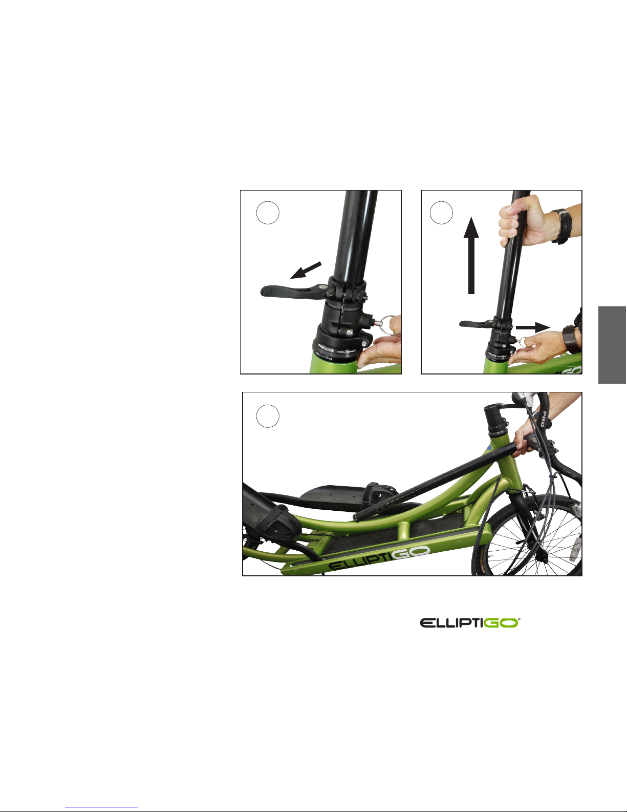
The Storage Position
To place the non-folding steering column
into the storage position, follow these
steps:
1. Open the steering extender quick
release.
2. Pull and hold out the safety index
pin with one hand while removing
the steering extender from the
base collar with the other hand.
3. The extender, stem, and handlebar
assembly can now be placed
securely near the ElliptiGO® bike
for storage.
II
1 2
3
Owner’s Manual
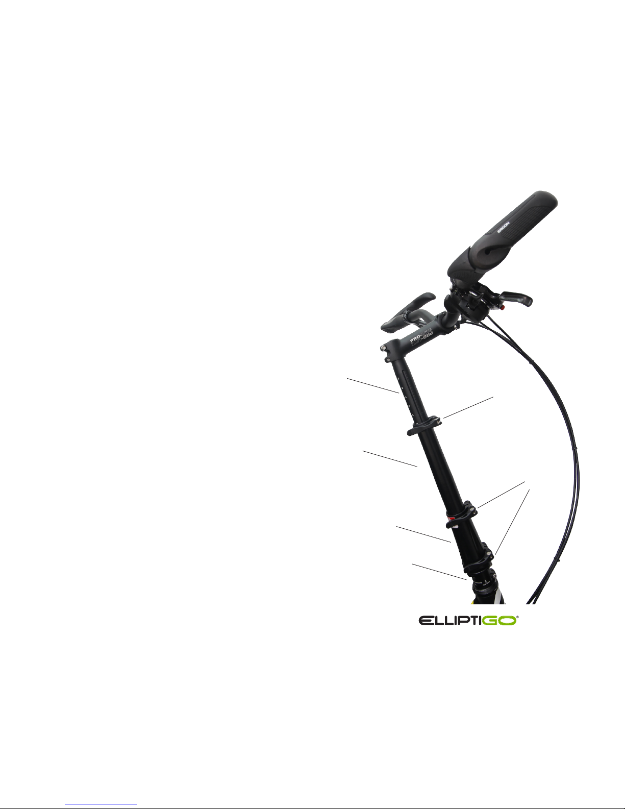
Folding Steering Column - Models 8S and 11R
8S and 11R model ElliptiGO bikes come equipped with a
steering column that telescopes to adjust the height of the
riding position and folds for the storage position. The folding
steering column consists of the following components:
1. The base
2. The collar
3. The column
4. The steering extender
5. The steering extender quick release
6. The steering collar quick releases
1
2
3
4
6
5

Owner’s Manual
The Riding Position
When in the riding position, the column extends vertically up from the
base, the steering extender is set to the correct depth in the column,
the bottom of the collar is flush with the top flange of the base and set
to the “LOCK” position, and all quick release levers are firmly closed.
The correct steering extender depth is reached when the handlebar
height is the most comfortable for the rider when riding and the “MAX
EXTENSION” line is not visible above the base. This height is usually set
so that the rider stands tall when riding with little to no weight on his/
her hands or wrists.
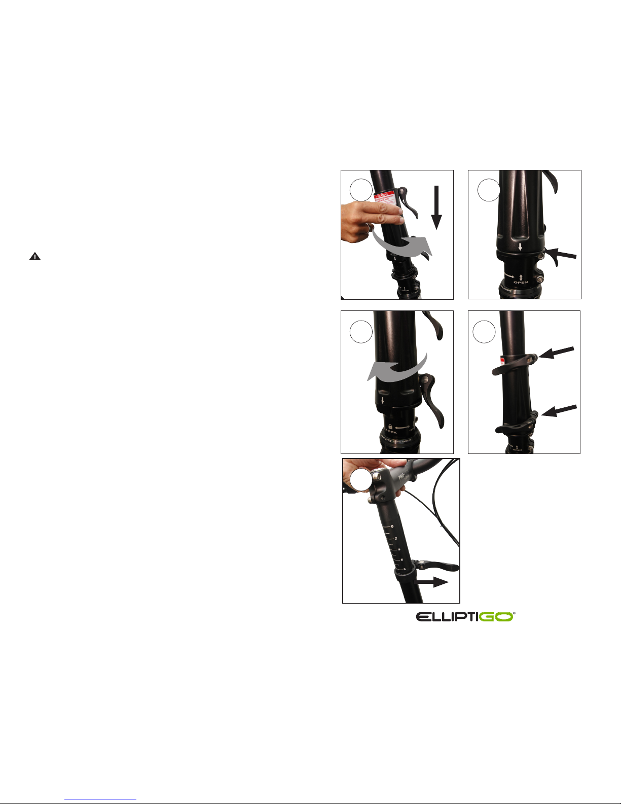
To place the folding steering column into the riding position,
follow these steps:
1. Place the bike on the kickstand.
2. Open both collar quick releases.
3. Slide the collar towards the handlebars along the steering
column to clear the pivot.
4. Lift the steering column up into the vertical position so
that it is in-line with the base.
2
3
4
II
Owner’s Manual
5 6
NO GAP
5. Rotate the collar so that the arrow aligns with the “OPEN”
marking on the right side of the steering base.
6. Slide the collar down over the pivot until the bottom of
the collar sits flush on the flange of the base.
WARNING! ENSURE THAT THERE IS NO GAP BETWEEN
THE BOTTOM OF THE COLLAR AND THE STEERING BASE
FLANGE! Allowing a gap between the collar and the base
could result in the collar rising above the pivot during a ride
and the entire steering column collapsing unexpectedly. This
would likely result in the rider losing control and suering
serious injuries from an ensuing fall.
7. Rotate the collar clockwise until the arrow on the collar
aligns with the “LOCK” marking on the back of the
steering column base.
8. Close both collar quick releases to lock the collar onto the
steering column. The force applied to closing the lever
should leave an imprint in your hand. See the section on
Quick Release Clamping Systems above for details.
9. Open the steering extender quick release.
7
8
9

Owner’s Manual
10. Slide the extender until the handlebars are at a desired riding
position. Ensure that the “MAX EXTENSION” line on the steering
extender is not visible above the base.
WARNING! ENSURE THAT THE “MAX EXTENSION” LINE ON THE
STEERING EXTENDER IS BELOW THE TOP OF THE BASE! Riding
while the “MAX EXTENSION” line is above the base could result in
the steering extender breaking during operation or being pulled out
of the base, causing a fall. Never use an ElliptiGO product with the
“MAX EXTENSION” line visible above the base.
11. Close the steering extender quick release lever firmly, using the
steering column for leverage. The force applied to closing the
lever should leave an imprint in your hand. See the section on
Quick Release Clamping Systems above for details.
WARNING! Securing the quick releases properly is critically
important. Failure to do so could result in the steering extender
collapsing or being removed unexpectedly while riding, causing
the rider to fall and be seriously injured. Make sure to follow the
instructions set out in the Quick Release Clamping Systems section
when closing a quick release lever.
WARNING! The steering column is one of the most important
safety features on ElliptiGO products. Before you ride, it is critical
that you ensure it has been secured properly in the riding position
and the quick release levers are fully closed with the appropriate
amount of tension. Failure to properly secure the steering column
into the riding position before riding can result in the unexpected
folding of the steering column and failure to secure a quick release
can result in the unexpected collapsing or removal of the steering
column extender, any of which will likely cause the rider to fall and
be seriously injured or killed.
10
II
11
Do not
exceed MAX
EXTENSION
line.
Owner’s Manual
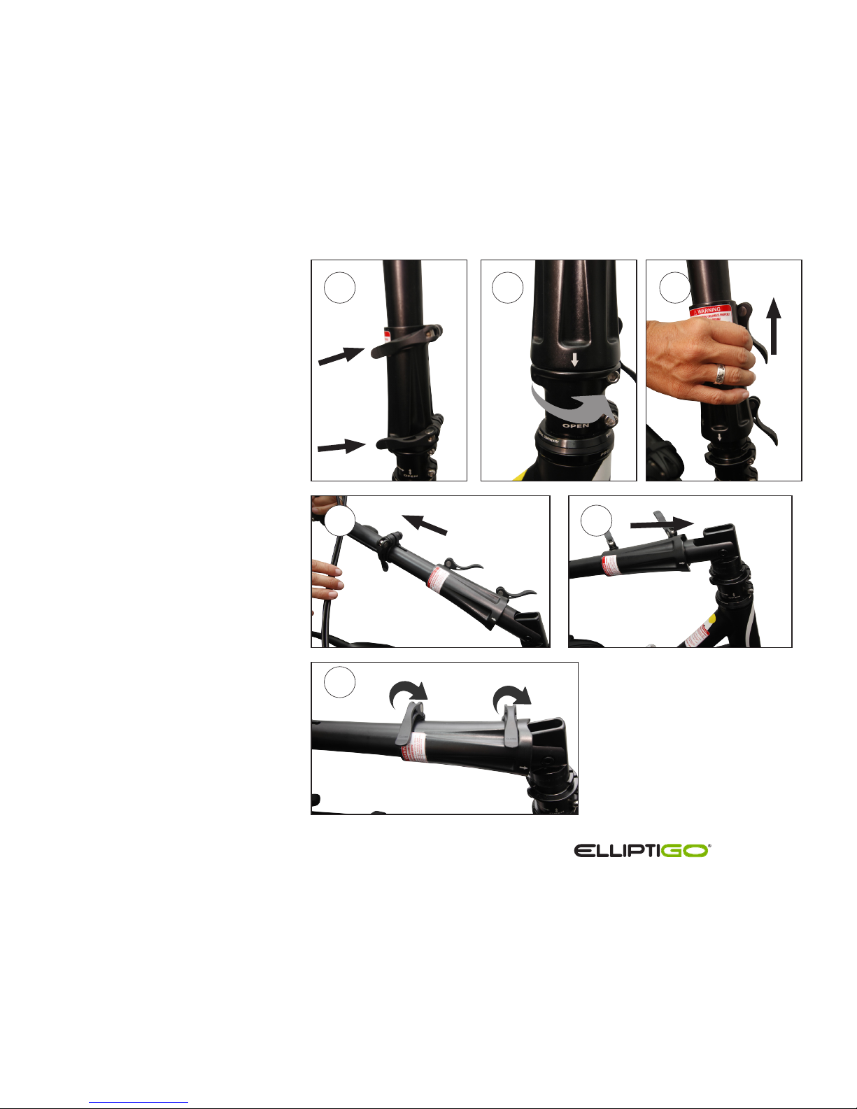
The Storage Position
To place the folding steering column
into the storage position, follow these
steps:
1. Open both collar quick releases.
2. Rotate collar 90 degrees counter clockwise until index mark on collar
lines up with “OPEN” mark on base.
3. Slide collar up above folding pivot.
4. Fold the steering column inward
toward the center of the bike 90
degrees.
5. Slide the collar back so the groove
on the collar engages the steering
base.
6. While holding the collar tight
against the steering base,
close both collar quick-releases
to lock into the storage position.
1
2 3
4
5
6

Owner’s Manual
Brakes
Your elliptical bike comes equipped with front and rear rim brakes
actuated by hand levers attached to the handlebars. One lever actuates
the front brake and the other actuates the rear brake. The brakes are
comprised of the following components:
1. Left brake pad
2. Left caliper
3. Brake noodle
4. Quick release bracket
5. Brake cable boot
6. Brake cable
7. Right caliper
8. Right brake pad
3
4
6
1
8
2 7
5
II
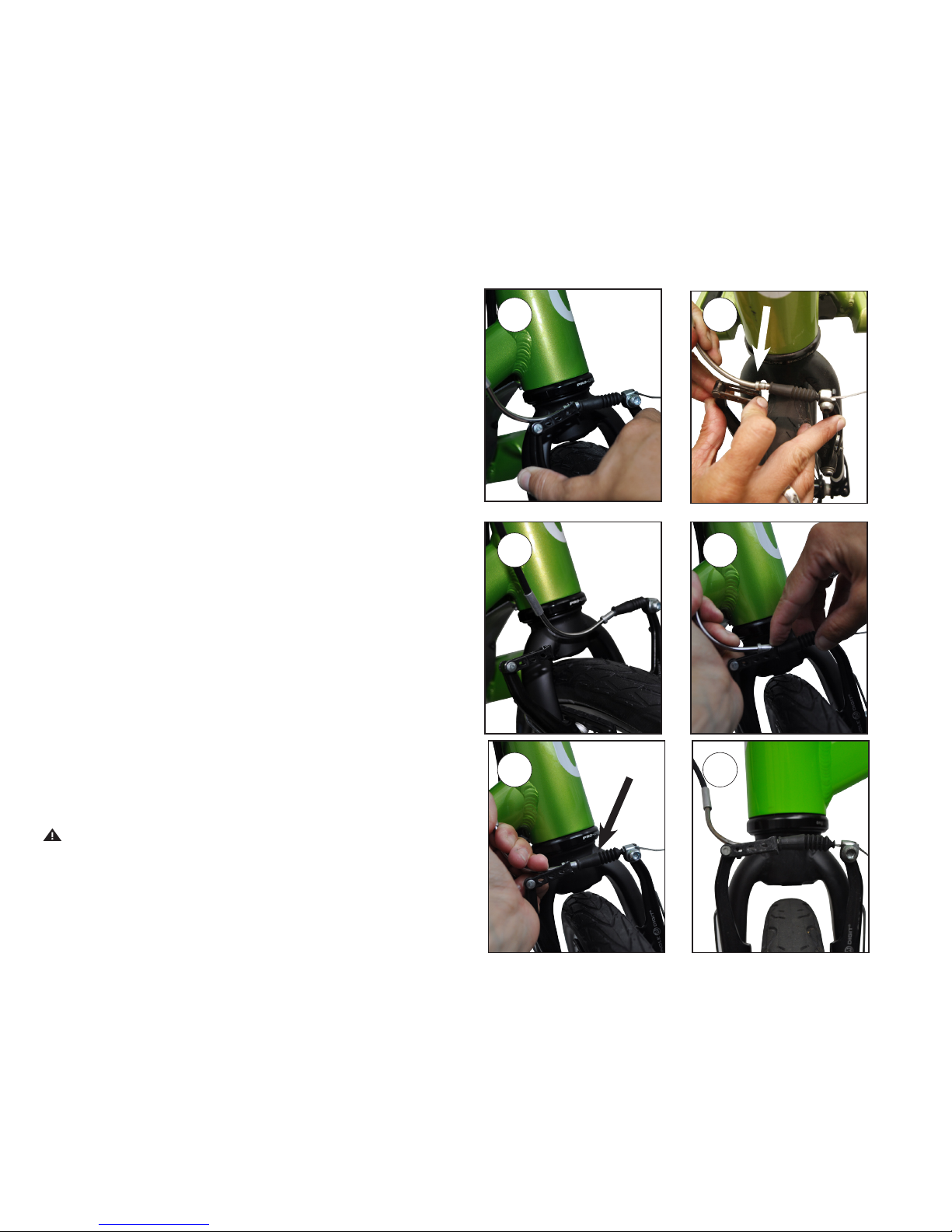
Each brake has a quick release mechanism that enables the
corresponding wheel to be removed without deflating the
tire. To open the brake quick release system, follow these
steps:
1. Place the bike on the kickstand.
2. With one hand, squeeze the calipers together.
3. While holding the calipers, use the other hand to
pull the brake noodle towards the hinge of the
bracket (towards the left caliper). Use a finger of the
hand squeezing the calipers to push the bracket
cage down while simultaneously pulling up on the
brake noodle so that the brake cable passes through
the slot in the top of the quick release bracket.
4. Release the calipers so that they can spring open.
To close the brake quick release system, follow these
steps:
1. Place the bike on the kickstand.
2. With one hand, squeeze the calipers together.
3. With the other hand, pull the brake noodle towards the
hinge of the bracket and slide the cable through the
slot in the bracket. Then release the brake noodle so
that it slides through the large hole at the edge of the
bracket.
4. Release the calipers and test the brakes by actuating
the corresponding brake lever on the handlebars and
ensuring the close properly.
WARNING! Ensure that the brake quick release system is
properly closed and your brakes are functioning properly
before riding your bike. If the brake quick release system
is open or closed improperly, the brake will not function.
Riding without operating brakes is extremely dangerous
2
4
3
3
2
4

Owner’s Manual
II
and drastically increase the likelihood that the rider will
collide with another object and suer serious injury.
The correct way to apply the brakes under normal stopping
conditions is to gently actuate both levers, having the rear
brake engage the rear rim first and then slowly applying
the front brake until it engages the front rim, then applying
force to lever simultaneously to bring the bike to a smooth,
controlled stop.
However, there is more to it than this, especially in
emergency braking situations. Braking force is at its peak
just before a wheel “locks up” and starts to skid. Once a
wheel locks up, the braking force is greatly reduced and,
more importantly, the bike becomes extremely dicult to
control. The important skill to learn to optimize braking
eectiveness is how to get to the maximum braking force
quickly without locking up a wheel. This is best done
by smoothly and eciently increasing the braking force
until maximum braking force is reached, as opposed to
pulling the brakes to the point of maximum braking force
immediately, which will likely result in overshooting on one
or both brakes, causing tire lock up and skidding.
WARNING! Always apply the brakes in a smooth
controlled manner. Start braking with the rear brake first,
but always use both brakes to control speed. Applying
the brakes too quickly or with too much force can result
in a wheel “locking up” and the rider losing control and
suering a fall.
Be aware that as you slow down, inertia will cause your
body weight to move forward. The quicker you slow down,
the quicker your body weight will shift forward. This eect
makes avoiding rear wheel lock up even more challenging
because one of the variables that determine when a wheel
will lock up is the amount of weight supported by that
wheel. The lighter the weight, the less force required to
lock up the wheel. As a result, proper braking requires an
adjustment for this shift in body weight as well as an active
eort on your part to minimize this eect by consciously
shifting your weight rearward during braking. However,
usually to accommodate for this shift in body weight, you
should apply more braking force to the front wheel and
less to the rear wheel as the rate of deceleration increases
and your weight is disproportionately borne by the front
wheel. This weight distribution inequality becomes even
more pronounced when braking downhill. The declined
slope encourages a greater shift in weight towards the
front wheel during deceleration, increasing the likelihood
of a rear wheel lock up and requiring more braking force to
be placed on the front wheel during an emergency stop.
Also, as discussed above, wet road conditions greatly
reduce the stopping ability of an elliptical bike. Rim brakes
rely on friction between the brake pad and the rim to slow
rotation of the wheel. A wet rim will reduce the amount
of friction that can be generated, especially at the initial
stages of braking. Similarly, a wet road surface reduces
the amount of traction for the tires, allowing the wheels to
lock up more easily. These are two of the primary reasons
why we discourage riding during wet conditions. If you
must ride when the roads are wet, then the best way to
adjust for this loss in stopping power is to slow down, to
 Loading...