

Elliott Roto-Jet I 0620AR, Roto-Jet I 0620A Operating And Maintenance Instructions Manual

0620A \ 0620AR Roto-Jet I
(Supersedes Models 0600, 0600R, 0620, and 0620R)
Tube & Pipe Cleaners Tube Testers Tube Plugs Tube Removal Tube Installation
™
Cleaning System
Operating and Maintenance Instructions
www.elliott-tool.com


Table Of Contents
Introduction .......................................................................................................... 4
Safety ................................................................................................................... 5
Operation .............................................................................................................. 8
Operating Position (Diagram A) ............................................................................ 9
Drive Coupling (Diagram B) ................................................................................ 11
Electrical ............................................................................................................. 14
Plug Grounding (Diagram C & D) ........................................................................ 15
Schematic (Diagram E) ....................................................................................... 17
Maintenance ....................................................................................................... 18
Technical Data .................................................................................................... 19
Trouble Shooting Guide ...................................................................................... 21
Records ...................................................................................................... 24 & 25
Parts List 0620A ................................................................................................. 26
Parts List 0620AR ............................................................................................... 28
Flexshaft Repair ................................................................................................. 30
0620A Roto-Jet I 3

INTRODUCTION
Thank you for purchasing this Elliott product. More than 100 years of experience have been employed
in the design and manufacture of this control, representing the highest standard of quality, value and
durability. Elliott tools have proven themselves in thousands of hours of trouble free eld operation.
If this is your rst Elliott purchase, welcome to our company; our products are our ambassadors. If
this is a repeat purchase, you can rest assured that the same value you have received in the past will
continue with all of your purchases, now and in the future.
The Elliott Roto Jet I™ has been designed for cleaning tubes in the following types of equipment:
Heat Exchangers
Condensers
Chillers
If you have any questions regarding this product, manual or operating instructions, please call Elliott at
+1 800 332 0447 toll free (USA only) or +1 937 253 6133, or fax us at +1 937 253 9189 for immediate
service.
4 0620A Roto-Jet I
SAFETY
Read and save all instructions. Before use, be sure everyone using this machine reads and under-
stands this manual, as well as any labels packaged with or attached to the machine.
WARNING
When using electric equipment, always follow basic
safety precautions to reduce the risk of re, electric
shock and personal injury.
WARNING
To reduce the risk of injury, always unplug your machine
before performing any maintenance. Never
disassemble the machine or try to do any wiring
on the electrical system. Contact Elliott for all repairs.
1. Know Your Elliott Roto-Jet I™. Read this manual carefully to learn your tool’s applications and
limitations, as well as potential hazards, associated with this type of equipment.
2. Ground Your Elliott Roto-Jet I™. Always use properly grounded electrical outlets, and if using an
extension cord, make sure that it is of the proper size for the electrical load and it is equipped with a
ground wire and ground plug. See “Electrical” section for further information.
3. Avoid Dangerous Environments. Do not use your Elliott machine around or in the presence of
explosive atmospheres (gaseous fumes, dust or ammable materials). Remove materials or debris
that may be ignited by sparks.
4. Keep Work Area Clean and Well Lighted. Cluttered, dark work areas invite accidents.
5. Dress Properly. Do not wear loose clothing or jewelry. Wear a protective hair covering to contain long
hair. It is recommended that the operator wear safety glasses with side shields or a full face shield eye
protection. Gloves and water repellant, nonskid footwear are also recommended. Keep hands and
gloves away from moving parts.
6. Use Safety Equipment. Everyone in the work area should wear safety goggles or glasses with side
shields complying with current safety standards. Wear hearing protection during extended use,
respirator for a conned space and a dust mask for dusty operations. Hard hats, face shields, safety
shoes, respirators, etc. should be used when specied or necessary. Keep a re extinguisher nearby.
7. Keep Bystanders Away. Bystanders should be kept at a safe distance from the work area to avoid
distracting the operator and contacting the exshafting, machine or extension cord. Only the operator
of the machine should engage the foot switch control. NEVER PLACE A WEIGHTED OBJECT ON THE
FOOT SWITCH TO PRODUCE CONTINUOUS OPERATION OF THE MACHINE.
8. Protect Others in the Work Area from debris such as water exhaust and water spray. Provide barriers
or shields as needed.
0620A Roto-Jet I 5

SAFETY (CONT.)
9. Use the Right Cleaning Device. Do not use a cleaning device or attachment to do a job for which it
is not recommended. Refer to the Elliott E-100 catalog for all optional equipment. Do not alter the
machine or cleaning device, this will void the warranty on the product.
10. Use Proper Accessories. Use Elliott accessories only. Be sure accessories are properly installed
and maintained. Do not defeat a guard or other safety device when installing an accessory or
attachment.
11. Check for Damaged Parts. Inspect guards and other parts before use. Check for misalignment,
binding of moving parts, improper mounting, broken parts or any other conditions that may affect
operation. If abnormal noise or vibration occurs, turn the machine off immediately and have the
problem corrected before further use. Do not use a damaged machine. Tag damaged machines “Do
Not Use” until repaired. A guard or other damaged part should be properly repaired or replaced by
an Elliott service facility. For all repairs, insist on only identical replacement parts.
12. Remove All Wrenches. Check that all accessory wrenches are removed from the system before
turning it on.
13. Guard Against Electric Shock. Hold the exshaft by the insulated nonmetal casing surfaces. Inspect
and test the Ground Fault Circuit Interrupter (GFCI) prior to each new use of the machine to ensure
its proper operation. For more information refer to the “Electrical” section.
14. Avoid Accidental Starting. Be sure your machine is turned off before plugging it in. Do not use a
machine if the foot switch control does not turn the machine on and off. NEVER USE ANY OBJECT
TO HOLD THE FOOT SWITCH IN THE “ON” POSITION.
15. Do Not Force the Flexshaft. Your Elliott Roto-Jet™ will perform best at the rate for which it was
designed. Excessive force only causes operator fatigue, increased exshaft wear, shaft or break
away coupling failure.
16. Keep Hands Away from All Moving Parts.
17. Do Not Abuse Cord. Never carry your machine or foot switch by its cord. Never unplug the machine
by yanking the cord from the outlet. Pull the plug rather than the cord to reduce the risk of damage.
Keep the cord away from heat, oil, sharp objects, cutting edges and moving parts.
18. Do Not Overreach - Maintain Control. Keep proper footing and balance at all times.
19. Stay Alert. Watch what you are doing, and use common sense. DO NOT use a machine when you
are tired, distracted or under the inuence of drugs, alcohol or any medication causing decreased
control.
20. Unplug Machine when it is not in use, before changing accessories or performing recommended
maintenance.
21. Maintain Machine Carefully. Keep handles dry, clean and free from oil and grease. Follow
instructions for lubricating and changing accessories. For more information see “Maintenance”
section. Periodically inspect the machine cord and extension cords for damage. Have damaged
parts repaired or replaced by an Elliott service facility.
22. Store Idle Machines. When not is use, store your machine in a dry, heated, secured place. For more
information see “Maintenance” section.
6 0620A Roto-Jet I

SAFETY (CONT.)
23. Maintain Labels and Nameplates. These carry important information and will assist you in ordering
spare and replacement parts. If unreadable or missing, contact an Elliott service facility for a
replacement.
24. Stop the Machine Immediately if the Flexshaft Starts to Coil. Flexshaft damage will occur if exshaft is
operated in a coiled position.
25. Use the Proper Flexshaft to t the tubes to be cleaned. Never use a exshaft that is too small or too
short. Flexshaft failure will result if too great a resistance is placed on the exshaft. Refer to the chart
below for sizing information. (See Fig. 1 and 2)
Wet Shafts (Fig.1)
Prex Part Number Casing Outside Diameter Tube Inside Diameter
inch mm inch mm
0511*(xx) .250 6 5/16 - 3/8 8 - 10
0512*(xx) .375 10 7/16 - 1/2 11 - 13
0513*(xx) .500 13 9/16 - 1 14 - 25
0514A*(xx) .625 16 3/4 - 1-1/2 19 - 38
0514*(xx) .750 19 1 - 2 25 - 50
0515*(xx) 1.000 25 2 and over 50 and over
*Length of shaft in feet completes the part number.
(Available in standard lengths of 16’, 25’, 33’, and 49’. Consult factory for additional lengths.)
Dry Shafts (Fig.2)
Prex Part Number Casing Outside Diameter Tube Inside Diameter
inch mm inch mm
0534*(xx) 7/8 22 1 and over 25 and over
*Length of shaft in feet completes the part number.
(Available in standard lengths of 25’, 35’, and 50’. Consult factory for additional lengths.)
0620A Roto-Jet I 7

OPERATION
Correct Machine Position and Operation is critical to getting the job done quickly and efciently.
This can be accomplished by the following these steps:
Examine the tubes to be cleaned and measure the internal diameter (Elliott Tube Gage is
recommended) and length of the tubes. If the tube ends are expanded, then make a note of the
smallest internal diameter. Record these measurements on the charts provided on page 22 and 23
of this manual. You will need these measurements to select the proper size exshaft and cleaning
attachments.
TOOL TIP
Always select a smaller size of cleaning device for heavy
tube deposits. With the exception of the Elliott Turbo Brush,
never use a brush or cleaning device larger than the internal
diameter of the tubes.
Roll or hand carry the machine to the location where the cleaning will take place.
Position the machine at a right angle to the tube sheet or cleaning area. This will keep the exshaft
at the proper radius. NEVER OPERATE THE MACHINE IN THE VERTICAL POSITION. (See Diagram
A page 7).
Remove pin from handle bracket and lower handle on the machine to its lowest setting and replace
the handle pin.
Lower the machine to the horizontal position, resting the end of the handle on the oor.
Open the foot switch storage compartment and remove the foot switch, “O” ring, and rubber hose
washer.
Position lug on foot pedal plug to line-up with slot in plug receptacle and push plug in place. Then
thread the outer ring of the foot pedal plug onto the plug receptacle until tight. The foot switch can
only be connected in one position.
Place the rubber hose washer in the water hose connection of the machine. This is a one time
operation. The rubber washer can remain in this connection and does not require removal after use.
Connect a standard garden hose to the 3/4” water hose connection of the machine. The machine
is designed for “Municipal” water pressure only, Max 100 psi (6.89 Bar-Metric). DO NOT connect
the water connection to a “High Pressure” source. Water is important to the cleaning process as it
ushes away deposits cleaned from the tube and helps to lubricate and cool the exshaft.
Position the “O” ring in the recess of the exshaft connection manifold.
8 0620A Roto-Jet I
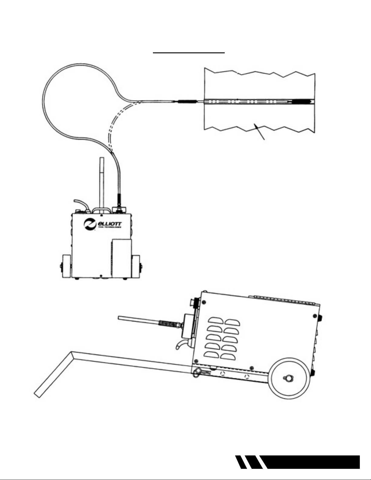
DIAGRAM A
TOP VIEW
Tube Bundle
Roto-Jet I
CORRECT OPERATING POSITION
0620A Roto-Jet I 9

OPERATION (CONT.)
Prepare the exshaft by loosening the four (4) set screws located in the brass locking sleeve using
a 3/32” Allen wrench. Thread the breakaway or solid square drive into the coupling adapter that
is swaged on the core of the exshaft. Position the brass locking sleeve equally over the coupling
adapter and the breakaway or solid square drive. Firmly tighten the four (4) Allen set screws. (See
Diagram B page 9)
Insert the square drive into the manifold of the machine. Rotate the exshaft by hand to properly seat
the square drive of the exshaft into the manifold. Thread the brass manifold cap onto the manifold of
the machine and rmly hand tighten.
Attach the chosen cleaning device to the tool coupling swaged to the core of the exshaft at the
opposite end from the manifold connection and rmly tighten the device.
TOOL TIP
For model 0620AR machines, to prevent the cleaning device from unthreading
when using the reverse mode of the machine, place a 1/4” lock washer
between the tool coupling and the cleaning device and rmly tighten the
connection.
Plug the machine into the appropriate electrical source. For more information see “Electrical” section.
Turn on the water supply.
Layout the exshaft as straight as possible. DO NOT start the machine with the exshaft in a coiled
position.
Depress the foot switch. The electric motor will operate and drive the exshaft, which will rotate
the cleaning device. At the same time, water will pass through the machine and out the end of the
exshaft casing near the cleaning device. Remove your foot from the foot switch and both the water
and rotation of the shaft will stop. Restart the machine and observe the water output from the end of
the exshaft casing. A constant stream of water should be discharged from the casing as the core
rotates. If no water is discharged from the exshaft, check the hose and hose connection for any
“kinks” that would restrict water ow. If there is no rotation of the exshaft, check the Ground Fault
Circuit Interrupter (GFCI) reset button. For more information see “Electrical” section. Depress the foot
switch again and observe the water ow from the end of the exshaft. If no water is discharged, from
the exshafting, discontinue use of the machine and contact an Elliott service facility.
For model 0620AR, let machine completely stop rotation before depressing the reversing peddle.
Reverse rotation and water ow will begin when the reverse peddle is depressed and will stop when
released.
10 0620A Roto-Jet I
 Loading...