

Ellies XS 2000 HT User Manual

XS 2000 HT User Manual

2
INDEX
Before the installation pag. 3
Introduction to the use pag. 4
1 Remote control functions pag. 5
2 Input panel and keys pag. 6
3 Connections inputs pag. 7
- Possibilities of connection to the VGA input
4 Adjustment via remote control and control rear panel pag. 9
5 Banks memorizations pag. 11
- Guide: how to use the bank
- Pre-memorization (factory pre-set)
- Example of personalization
- Chart of the prememorized banks
6 List of the menu regulations pag. 14
7 Menu ADJUSTMENT pag. 15
- Brightness, Contrast, Color, Hue, Black Plus, Gamma
8 Menu QUALITY pag. 17
- Peaking, CTI, NTSC matrix
9 Menu WHITE BALANCE pag. 18
- R G B dark , R G B bright
10 Menu SERVICE pag. 18
- Cut-off
- White peak
- W. P. Mode pag. 19
- B Plus
- Language
11 Menu SOURCE pag. 20
- Input Select, Standard, Comb Filter, VCR/TV
12 Menu SIZE ADJ. pag. 22
- V. size, H.size, H. fase, Keystone, Pincushion
13 Menu CONVERGENCE pag. 22
- SHIFT R G B é ê R G B ç è
- Corner Adjust, Blanking Top Left Right
14 Test: internal crosshatch pag. 24
15 Function of key "A" of the remote control pag. 25
(invert keystone V)
16 Function of key "B" of the remote control pag. 25
(non standard VGA versions)
3
Before installing, connecting and using the videoprojector
Before proceeding with the installation of the videoprojector, please read carefully the
handbooks supplied which contain all information you need for the installation, initial
set-up and the use of the videoprojector.
For a correct installation and a proper connection of the video sources, we recommend
you to ask for the technical support.
Originally the projector is adjusted for the frontal floor projection and by default it
projects on a 2m x 1.5m screen.
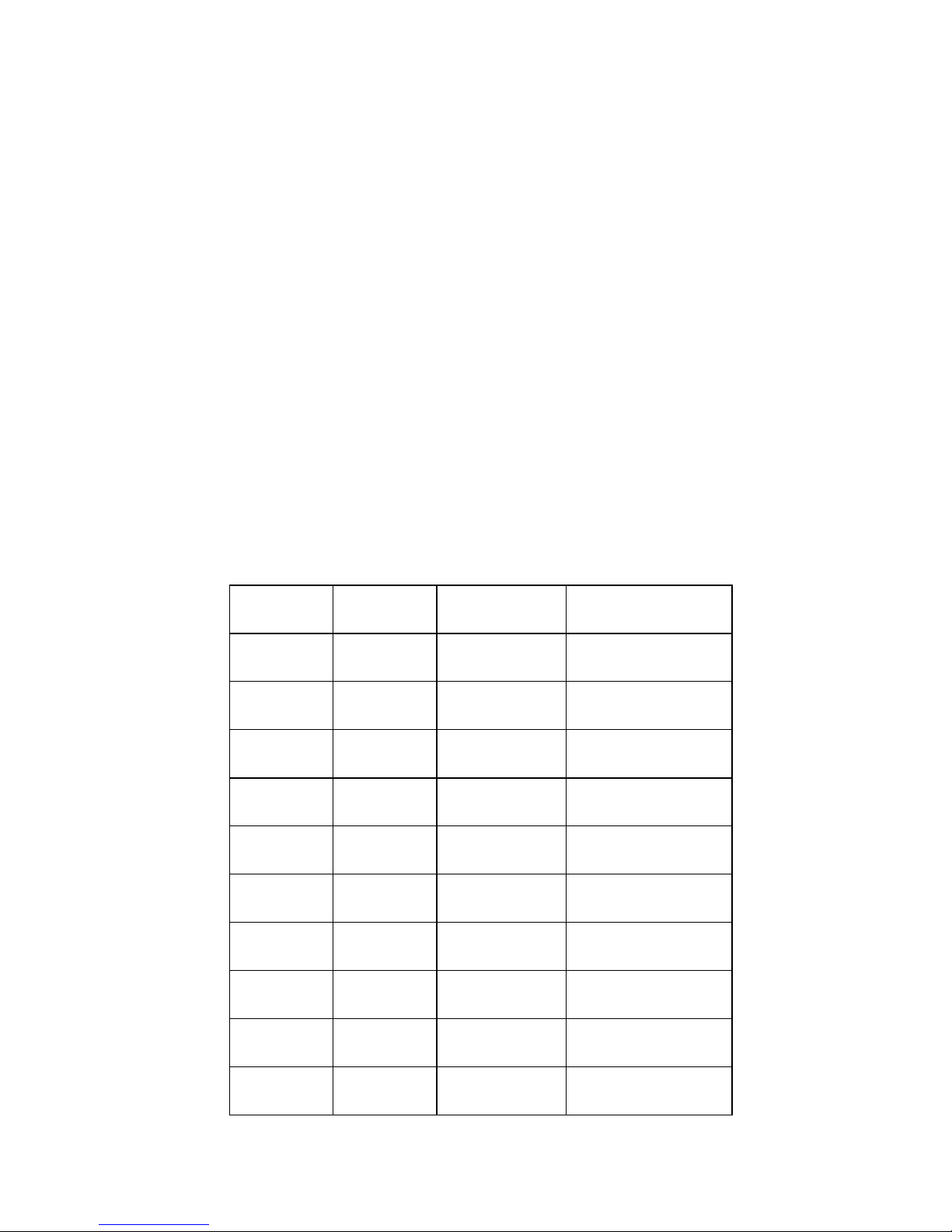
The projector has a initial default configuration for the memory banks, which can be
programmed again as the customer wishes to, and which represents a goods starting
base for the initial set-up operations. Below follows a list of all main configuration
features saved by default and the installation handbook describes some further details
on this matter.
KEY INPUT STANDARD FORMAT
1 VIDEO1 PAL 4:3
2 VIDEO2 PAL 4:3
3 S-VHS PAL 4:3
4 VIDEO1 PAL 16:9
5 S-VHS PAL 16:9
6 VGA IN 640 x 480 VGA 31.5 KHZ
7 VGA IN 800 x 600 VESA 36 KHZ
8 VGA IN 1024 x 768 XGA 35.5KHZ
9 VGA IN 640 x 480 CUSTOM
0 VIDEO1 TEST

4
INTRODUCTION TO THE USE OF THE VIDEOPROJECTOR
The commands of the XS 2000 HT are designed for using the videoprojector in the
easiest and the most straightforward way possible, still maintaining the possibility of
acting on all parameters, also the specifically technical ones, by means of a infrared
remote-control.
After having correctly performed the installation and the initial set-up, the user can
display the image as he wishes, optimally adjusting it by simply pressing one of the
selection buttons from 0..to 9 on the remote control.
During the initial adjustment each one of the 10 buttons is matched, by saving, to the
video source and its wide range of functions and adjustments.
The user may save a new condition or retrieve the last one he saved for each button
any time he likes.
From the remote control the user may also adjust the Brightness, Colour, Contrast and
the Chroma control (for the NTSC standards).
The operations for selecting the inputs, the standards, the options, and to fix the
dimensions and the quality of the image may be performed directly from the remote
control and can be reached by scrolling the menu options displayed (OSD).
When pressing any of the four “arrow” buttons, the menu is made active on the screen
With the é
and ê buttons you can select the option or the "SUB-MENU" you wish.
With the ç and è buttons you may change the function you wish.
The "OSD" disappears automatically after about 10 seconds from the last operation.
A control panel on the projector grants the possibility of controlling the projector in
case the remote control is not working (batteries empty).
To modify or add the configurations, you may temporarily or permanently change the
options and the adjustments, read the rest in this handbook, which describes all
possible operations and adjustments in detail.
5
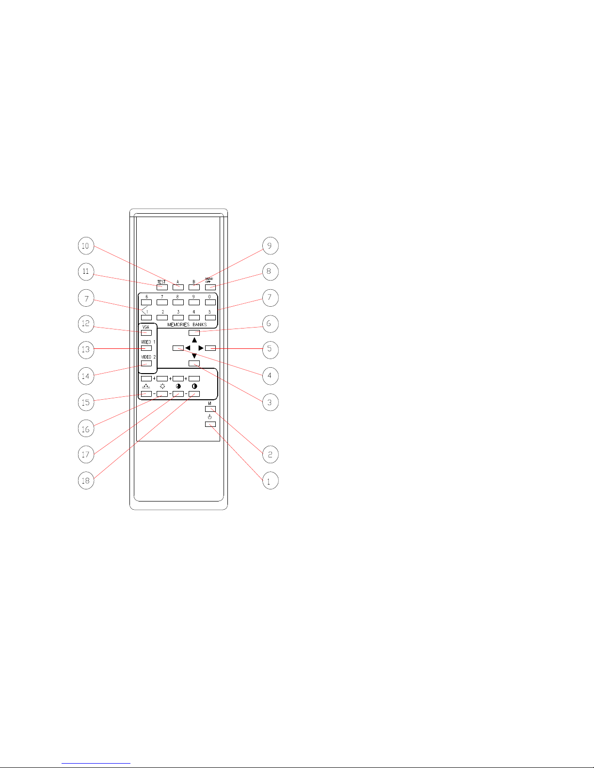
1. THE REMOTE CONTROL
Control and Functions
NOTE
Functions preceded by the // symbol are
activated by pressing the button for a
few seconds.
// Activate test signal in service mode
12.- VGA 1. - Stand-by / On//- On su bank R
2. - Memory
3. - Enter menu - Move menu cursor down ê
4. - Quit menu ç - Decrease selected function
5. - Enter menu è - Increase selected function
6. - Move menu cursor up é
7. - Recall memory bank
8. - Switch off OSD
9. - **//Force autosync
10.-**// Invert TRV
11.- Activate test signal select button
13.- Video1 select button
14.- Video2 select button // SVHS select button
15.- Tint +/- (NTSC)
16.- Brightness +/-
17.- Colour +/-
18.- Contrast +/-
Functions preceded by the **// symbol
are activated only when using test in the
service mode.

6
2. INPUT SOCKET AND CONTROLS
19.- Recall memory bank from 0 to 9.
20.- Stand-by / On
- Recall Bank R. (when switching on after pressing button 29)
21.- Save current configuration in the required Bank.
22.- Standard VGA input socket.
23.- Standard S-VHS input socket.
24.- Video 2 BNC input socket.
25.- Video 1 BNC input socket.
26.- Video 1 output socket crossover (closed 75 Ohm Jumper on board).
27.- Main fuse.
28.- Power socket 220V AC (110V AC).
29.- Power switch.
30.- Adjustment control using “OSD” menu functions.
31.- Infrared receiver.
7
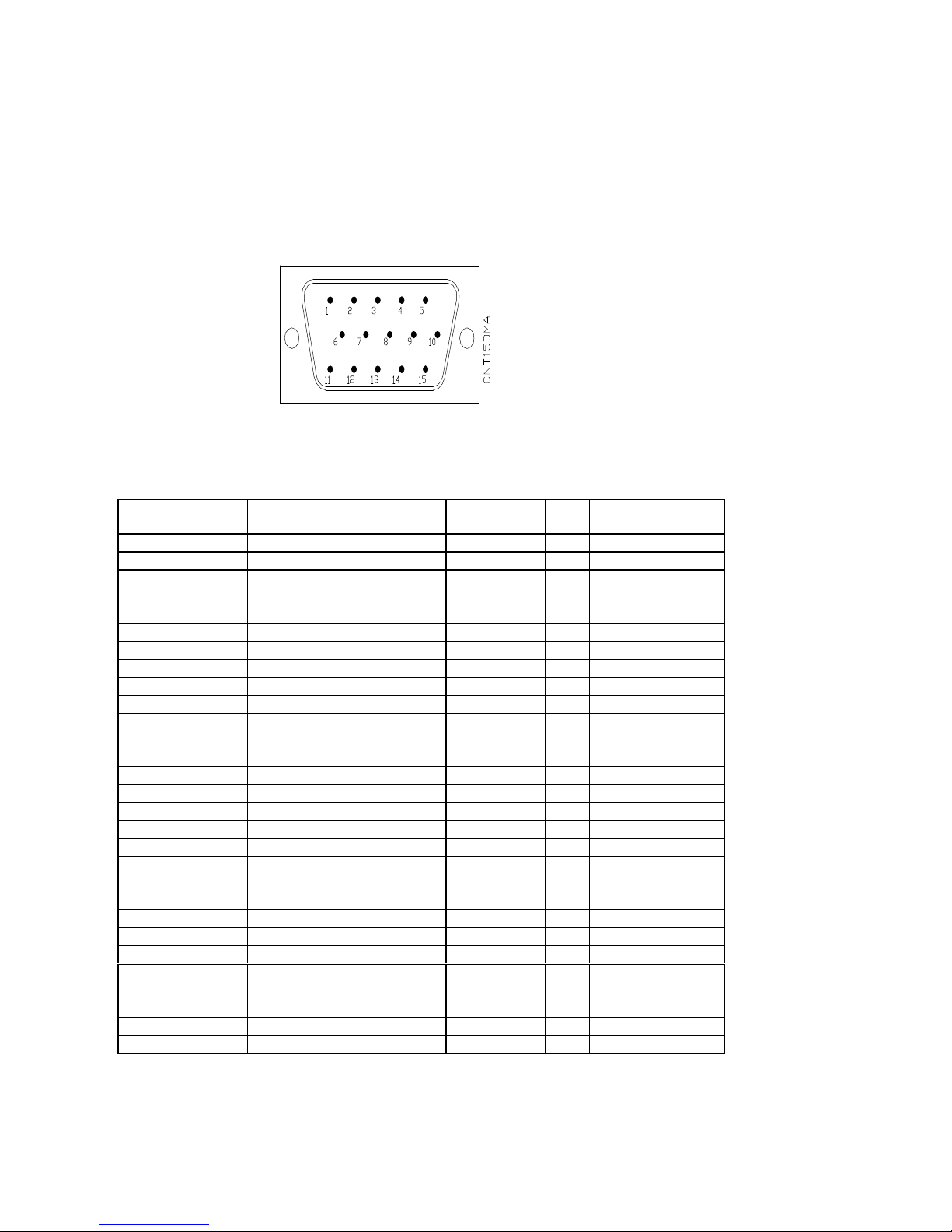
3. INPUT CONNECTIONS
VGA Input
pin1 red signal - pin2 green signal – pin3 blue signal – pin4-5-6- void –
pin6-7-8-ground – pin9 void – pin10 ground – pin11-12 void – pin13 H.
sync –pin14 V.sync- pin15 void
On this input can be connected standard VGA signal from PC graphic video boards,
whose specifications are compatible with the below chart:
SYSTEM
TITLE
RES
(H xV)
Hfreq
(Khz)
Vfreq
(Hz)
SyncHSync
V
Interl
VGA 640x350 640 x350 31.500 70.000 + - N
VGA 640x400 640 x 400 31.500 70.000 - + N
VGA 640x480 640 x 480 31.500 60.000 - - N
XGA (8514/A) 1024 x 768 35.522 86.851 + + Y
VESA VS901101 640 x 480 37.861 72.809 - - N
VESA 480 75Hz 640 x 480 37.500 75.000 - - N
VESA VG900601 800 x 600 35.156 56.250 + + N
VESA VG900602 800 x 600 37.879 60.317 + + N
NEC 3D PGC 640 x 398 30.303 60.000 - + N
NEC 8514/A 1024 x 768 35.52 86.96 + + Y
NEC VGA350 720 x 350 31.47 70.09 + - N
NEC VGA400 720 x 400 31.47 70.09 - + N
NEC VGA480 720 x 480 31.47 59.94 - - N
NEC EVGA350 720 x 350 37.86 84.13 + - N
NEC EVGA400 720 x 400 37.86 84.13 - + N
NEC EVGA480 720 x 480 37.86 72.81 - - N
NEC 31khz 720 x 240 31.00 100.00 - - N
NEC 38 Khz 782 x 600 38.00 60.703 + + N
NOKIA 447X 8 640 x 480 31.472 59.947 - + N
NOKIA 447X 9 640 x 350 31.472 70.094 + - N
SONY 20-SE 1 624 x 468 31.469 59.940 - - N
SONY 20-SE 2 720 x 400 31.469 70.087 - + N
SONY 20-SE 10 624 x 468 37.500 75.000 - - N
MTBI PC96XA 120 x 780 32.840 80.000 - - Y
MTBI TEST50 640 x 576 31.469 50.000 - - N
MTBI 31khz 738 x 500 31.500 60.000 - - N

8
Video 1, Video 2 Input Socket
Composite Video Input
1 Vpp +/- 3dB on 75 Ohm
Video 1 Output (crossover)
Video 1 crossover output.
If the socket is connected to a input with a 75 Ohm impedance
open jumper "J6" (on pcb 07/U board).
Signal "C" 250 m Vpp +/- 3dB on 75 Ohm
Signal "C" earth
 Loading...