

Page 1
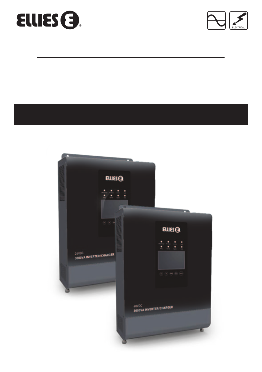
3000VA Inverter Charger
FBIC3000VA/24V & FBIC3000VA/48V User Manual
Please read this guide carefully before using this product
Page 2
CONTENTS
Important Safety Instructions 1
1. General Information 1
2. Installation Instructions 4
3. Interface Instruction 7
4. Protection 14
5. Troubleshooting 14
6. Maintenance 15
7. Technical Specifications 16
Notes 17
Important Safety Instructions
Please reserve this manual for future review.
• Please reserve this manual for future review. This manual contains all instructions about safety, installation and
operation for the inverter/charger.
• Read carefully all the instructions and warnings in the manual before installation.
• Non-safety voltage exists inside the inverter/charger, users must not dismantle it by itself in order to avoid personal
injury, contact professional maintenance personnel of our company in need of maintenance.
• Keep the inverter/charger out the reach of children.
• Do not place the inverter/charger in a damp, oily, inflammable and explosive or a severe environment with a large amount
of dust accumulation.
• The utility input and AC outp
ventilated places, it’s shell may produce heat during operation.
• It is suggested to install appropriate external fuses/breakers.
• Make sure switching o all connections with PV array and the fuse/breakers close to battery before inverter/charger
installation and adjustment.
• Make sure all connections remain tight to avoid excessive heat from a loose connection.
• It’s an o-grid inverter/charger, not for on-grid system.
• This inverter/charger can only be used singly, parallel or in series connections will damage the devices.
ut with high voltage, don’t touch wire connections. Install the inverter/charger in well
1. General Information
1.1 Overview
The UPower series is a new type of the inverter/charger combining with solar & utility charging and AC output, which adopts
a multi-core processor design and advanced MPPT control algorithm,
reliability and high industrialization standard. It oers four charging modes including Solar priority, Utility priority, Solar and
Utility & Solar; two output modes for Battery and Utility, meeting the various application demands.
The up-to-date optimized MPPT tracking technology is adopted for the PV charging modules. It can quickly track the
maximum power point of the PV array in any environment and acquire the maximum energy of solar panel in real time;
The advanced control algorithm is adopted for AC-DC charging modules that realize fully digitalized double closed-loop
control for voltage
DC charging voltage/current is continuously adjustable in a certain range, and the complete input/output protection
functions can oer stable and reliable charging and protection for the battery.
The DC-AC inverter modules are based on full digital and intelligent design. It adopts the advanced SPWM technology,
outputs the pure sine wave and converts 24/48VDC to 220/230VAC suitable for AC loads of household appliances, electric
tools, commercial units, electronic audio and video devices etc.
The product adopts 4.2 inch LCD display design, which real-time displays the operational data and running state of the
system. The comprehensive electronic protection function guarantees more safe and more stable operation of the system.
and current, with high control precision, small volume. The input range of AC voltage is wide, the output
and has the features of high response speed, high
Page 3
Features
• Adoption of the advanced SPWM technology, with pure sine wave output.
• Fully digitalized voltage and current double closed-loop control.
• Advanced MPPT technology, with eciency no less than 99.5%.
• Four charging mode: Solar priority, utility priority, utility & solar and solar only.
• Two OUTPUT mode: Battery and utility.
• LCD design that enables dynamic display of system running data and operating state.
• Provided with common interface and advanced interface.
• Multiple LED indicators that instantly indicate the operating state of the system.
• 2P circuit breaker provided at the utility input end.
• Independent control of AC output by AC OUT button.
• Battery temperature compensation function.
• Extensive electronic protection.
1.2 Characteristics
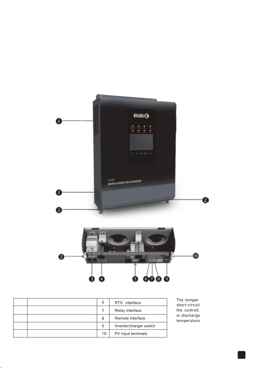
Figure 1 Product appearance
1
Ventilation RTS
Captive screw (2 pcs) Relay interface
2
AC output terminals Remote interface
3
Utility input terminals Inverter/charger switch
4
Battery input terminals PV input terminals
5
6
7
8
9
10
interface
The temperature sensor
short-circuited or damaged,
the controller will be charged
or discharged at the default
temperature 25 ºC.
2
Page 4

1.4 Schematic Diagram for Connections
Warning:Confirm the AC load power compatible with the power of the
inverter/charger, AC load selected exceeding the maximum output power
of inverter/charger is prohibited.
3
Page 5
2. Installation Instructions
2.1 General Installation Notes
• Please read the entire installation instructions to get familiar with the installation steps before installation.
• Be very careful when installing the batteries, especially flooded lead-acid battery. Please wear eye protection, and have
fresh water available to wash and clean if any contact with battery acid
• Keep the battery away from any metal objects, which may cause short circuit of the battery.
• Explosive acid battery gases may come out from the battery during charging, so make sure ventilation condition is good.
• Ventilation is highly recommended if mounted in an enclosure. Never install the controller in a sealed enclosure with
flooded batteries! Battery fumes from vented batteries will corrode and destroy the controller circuits.
• Lead-acid battery is only recommended, other kinds please refer to the battery manufacturer.
• Loose connections and corroded wires may result in high heat that can melt wire insulation, burn surrounding materials,
or even cause fire. Ensure tight connections and use cable clamps to secure cables and prevent them from swaying in
motion.
• Battery connection may be wired to one battery or a bank of batteries. The following instructions refer to a singular
battery, but it is implied that the battery connection can be made to either one battery or a group of batteries in a battery
bank.
• Select the system cables according to 5A/mm2 or less current density in accordance with Article 690 of the National
Electrical Code, NFPA 70.
• For outdoor installation, keep out of the direct sunshine and rain infiltration.
• High voltage still exists inside the inverter/charger after switching o the power switch, do not turn on or touch the
internal units, conduct the associated operation only after discharging the electric capacity.
• Do not place the inverter/charger in a damp, oily, inflammable and explosive or a severe environment with a large amount
of dust accumulation.
• Prohibit reverse connection at DC input end otherwise it may damage the equipment or unpredictable danger will occur.
The utility input and AC output are of high voltage, do not touch the wire connetion.
2.2 Wire Size & Breaker
The wiring and installation methods must follow all national and local electrical code requirements.
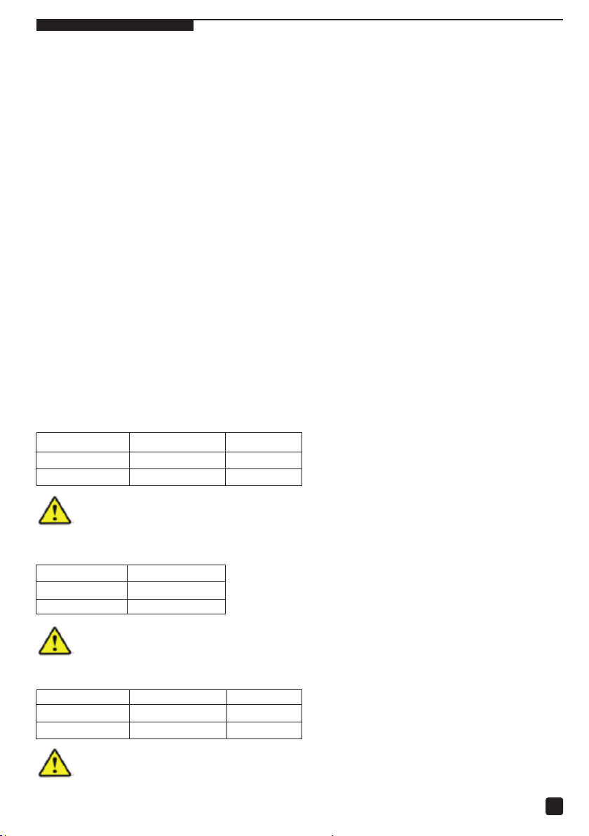
Recommended wire and circuit breaker of PV
Model PV wire size
FBIC3000VA/24V
FBIC3000VA/48V
10mm
6mm
2
/8AWG
2
/10AWG
Breaker
—
2P
—
2P
63A
32A
NOTE: When the PV modules connect in series, the open circuit voltage of the PV array must not exceed max.
PV input voltage at 25Cenvironment temperature.
Recommended wire of Utility
Model Utility wire size
FBIC3000VA/24V
FBIC3000VA/48V
6mm2/10AWG
2
6mm
/10AWG
NOTE: The utility input has the circuit breaker already and there is no need to add any more.
Recommended wire and circuit breaker of battery
Model Battery wire size Breaker
FBIC3000VA/24V
FBIC3000VA/48V
Type of circuit breaker is selected based on non-independent connection of inverter at the battery end
NOTE:
where there is no antherinverter connected.
2
/2AWG 2P— 200A
35mm
2
/6AWG 2P— 100A
16mm
4
Page 6
Recommended
FBIC3000VA/24V
FBIC3000VA/48V
wire and circuit breaker for AC output
Model AC w ire size Breaker
NOTE: The wire size used for connection is for reference only, use thicker wires to lower the voltage drop
and improve the system performance when the distance between the whole solar system components is far.
2
4mm
/12AWG 2P— 16A
2
4mm
/12AWG 2P— 16A
2.3 Mounting
NOTE: The above wire and the circuit breaker size
are for recommended use only, please choose the
suitable wire and circuit breaker according to the
practical situation.
Installation Steps
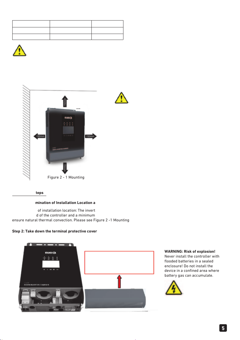
Step 1: Determination of Installation Location and Heat-dissipation Space
Determination of installation location: The inverter/charger shall be installed in a place with sucient air flow through the
dissipation pad of the controller and a minimum clearance of 150 mm from the upper and lower edges of the controller to
ensure natural thermal convection. Please see Figure 2 -1 Mounting
Step 2: Take down the terminal protective cover
Figure 2 - 1 Mounting
Screw o the screws and take
down the terminal protective cover
of the inverter/charger before
wiring.
WARNING: Risk of explosion!
Never install the controller with
flooded batteries in a sealed
enclosure! Do not install the
device in a confined area where
battery gas can accumulate.
6
5
Page 7

Step 3: Wiring
Determination of installation location: The inverter/charger shall be installed in a place with sucient air flow through the
dissipation pad of the controller and a minimum clearance of 150 mm from the upper and lower edges of the controller to
ensure natural thermal convection. Please see Figure 2 -1 Mounting
Figure: 2-2 Wiring Diagram
Connect the system in an order of battery load PV array Ground Utility in accordance with Figure
2-2: Wiring Diagram. Disconnect the system in the reverse order.
WARNING: Danger, High-voltage! Utility input, AC output and PV array will produce dangerous voltage,
make sure to disconnect the circuit breaker/ fuse before wiring.
WARNING: Do not turn on the circuit breaker/ fuse when wiring, and at the same time, ensure that
the wiring of “+”, “-” are correctly connected.
WARNING: A circuit breaker must be installed at the battery end, for selection, refer to Section 2.3
"Wire and Circuit Breaker".
Note: If the inverter/charger is to be used in an area with frequent lightning strikes, it is
recommended to install an external surge arrester at the PV input.
Grounding
Grounding connection must be made when utility is connected to the inverter/charger. The inverter/charger has
dedicated grounding terminal as shown in Fig. 2-2, the grounding must be reliable, the grounding wire shall be the
thicker wire (wire is not less than 4mm2, the grounding point shall be as close as possible to the invert
grounding wire shall be as short as possible.
AC output, Ground and PV wiring terminal use way:
1. When wiring, do not close the circuit breaker, and it is necessary to use a slotted screwdriver to unscrew the screws
for connecting their corresponding wires.
2. When removing the wirings, first the integrated machine must stop working, and then the screws shall be unscrewed by
using a slotted screwdriver, so as to dismantle their corresponding wires.
Step 5: Install the terminal protective cover
er/charger, the
6
Page 8
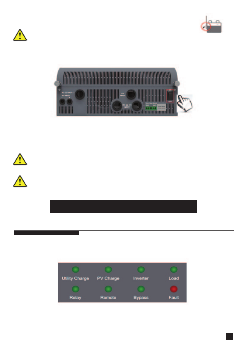
Step 6: Connect Accessory
Connect the remote temperature sensor cable (model: RTS300R47K3.81A) Connect one end of the
remote temperature sensor cable to the interface⑦ and place the other end close to the battery.
NOTE:
The temperature sensor short-circuited or damaged, the inverter/charger will
be charging or discharging at the default temperature 25C.
Step 7: Recheck if the wire connection is correct
Step 8: Rower on the inverter/ charger
①Turn on the circuit breaker at the battery end.
②Switch on the switch then the inverter indicator is on.
③Turn on the breaker of PV array and Utility.
④Turn on the AC load when the AC output is normal.
In case the power is supplied to the dierent AC loads, it is suggested to turn on the loads with larger
NOTE:
surge current, till the load working well, then turn on the loads with smaller surge current.
NOTE: In case the inverter/charger is not in normal operation, or LCD or indicator displays abnormal,
refer to Section 5 to clear the fault or contact the after-sale service personnel of our
NOTE: The installation steps and accessory list also refer to the cardboard
company.
3. Interface Instruction
3.1 Indicator
7
Page 9
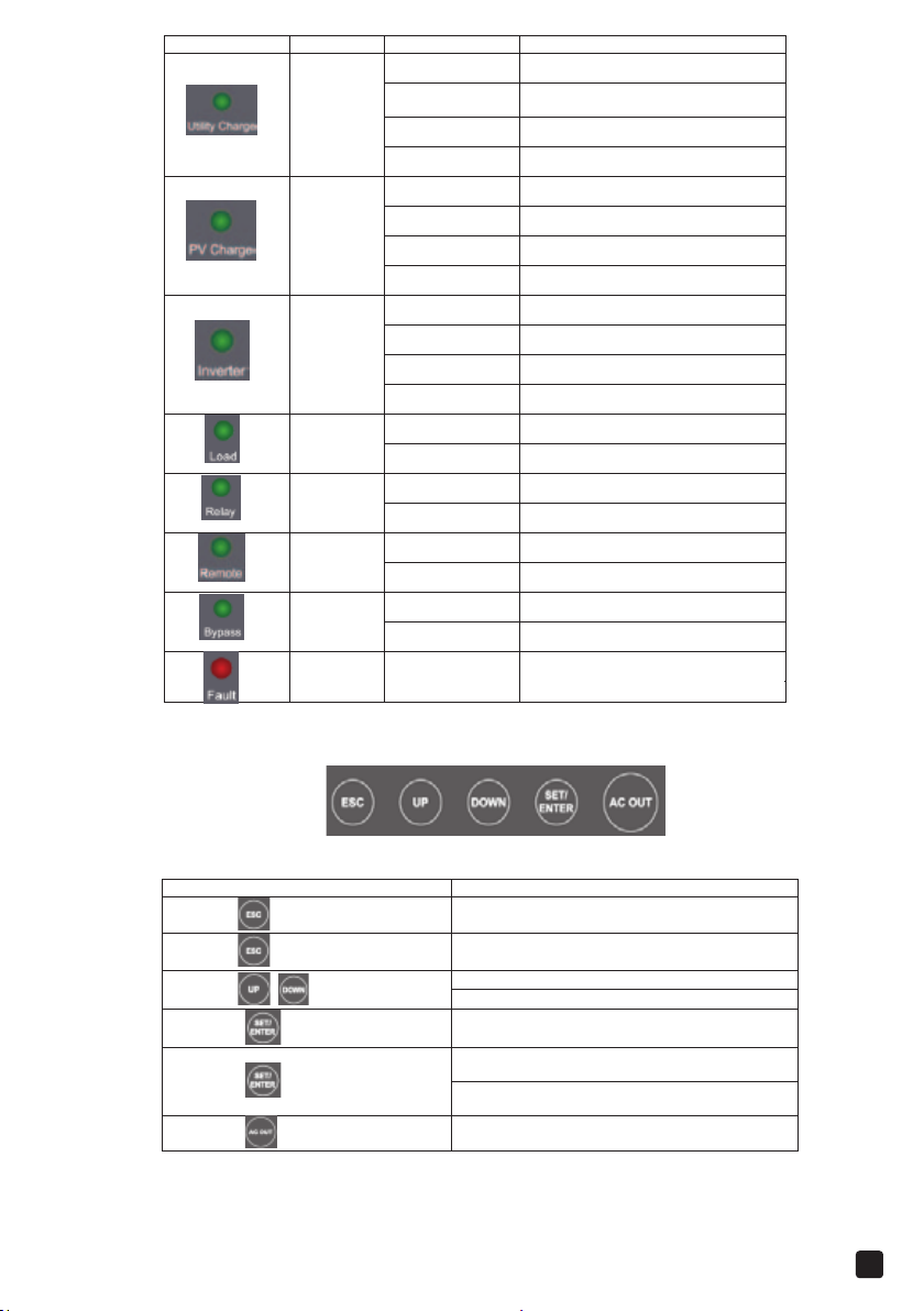
Indicator
Color
Status
Instruction
:
Switch the "Real Time Interface"over to" Set
OFF No utility input
Green
Green
Green
Green
Green
Green
Green
Red OFF Device normal
On Solid
Slowly Flashing
Fast Flashing
OFF No PV input
On Solid
Slowly Flashing
Fast Flashing
OFF Inverter turn o
On Solid Inverter turn on
Slowly Flashing
Fast Flashing
OFF No load output
On Solid Load output
OFF Relay turn o
On Solid Relay turn on
OFF Input voltage (3.3
On Solid
OFF Inverter output
On Solid Utility output
Utility connection normal but no
charging
Utility charging
Utility charge module fault
PV connection normal but no charging
PV charging
PV charge module fault
Inverter output
Inverter fault
〜
12VDC)
No Input voltage
3.2 Buttons
Operation Instruction
Press the button
Press the button and hold on 5s
Press the / button
Press the button
Press the button and hold on 5s
Press the button and hold on 5s
Exit the current interface
Clear the faults
Browse interface
Setting interface:Up / Down
Switch to Browse Parameter Column “Confirm
the setting parameters”
Browse Interface"
Switch the"Set Browse Interface" over to
"Parameter Setting Interface"
Inverter ON/OFF
Up / Down
8
Page 10
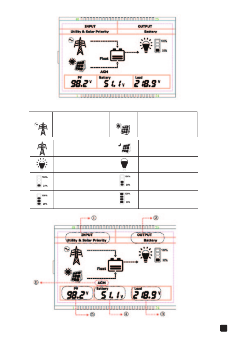
3.3 Real-time Interface
Icon instruction Icon instruction
Utility connected
No Utility
Load ON
Battery capacity level 8
Battery capacity level 50
〜
25%
〜
75%
PV connected
Battery capacity level 25〜50%
Battery capacity level 75〜100%
No PV
Load OFF
9
Page 11
Item
Setting
Content
①
Solar priority
AC output voltage
AGW
INPUT
②
OUTPUT
③
Load
④
Battery
⑤
PV
Utility
⑥
Battery Type
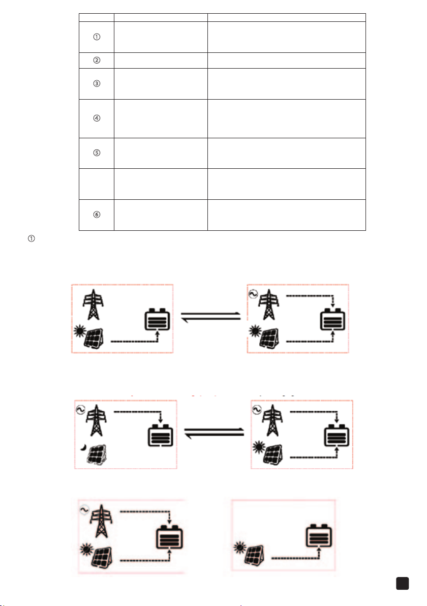
① INPUT
Solar priority
The battery is charged in solar priority mode and when the battery voltage is lower than “Auxiliary Module ON Voltage
(VAON)”, the utility starts charging. When the battery voltage reaches to “Auxiliary Module OFF Voltage (VAOF)”, the
utility stops charging.
Utility priority
The battery is charged in utility priority mode and when the battery voltage is lower than “Auxiliary Module ON Voltage
(VAON)”, the solar starts charging. When the battery voltage reaches to “Auxiliary Module OFF Voltage (VAOF)”, the
solar stops charging.
Utility priority
Utility & solar
Solar
Battery
Utility
AC output current
AC output power
AC output frequency
Battery voltage
Max. charging current
(PV charging current+ Utility charging current)
Battery temperature
Battery SOC
PV input voltage
PV charging current
PV charging power
PV charge energy
Utility input voltage
Utility charging current
Utility charging power
Utility charge energy
GEL
FLD
USER
VBAT < VAON
VBAT < VAOF
Utility & solar Solar
Utility & solar charging the battery Solar charging the battery
VBAT < VAON
VBAT < VAOF
10
Page 12
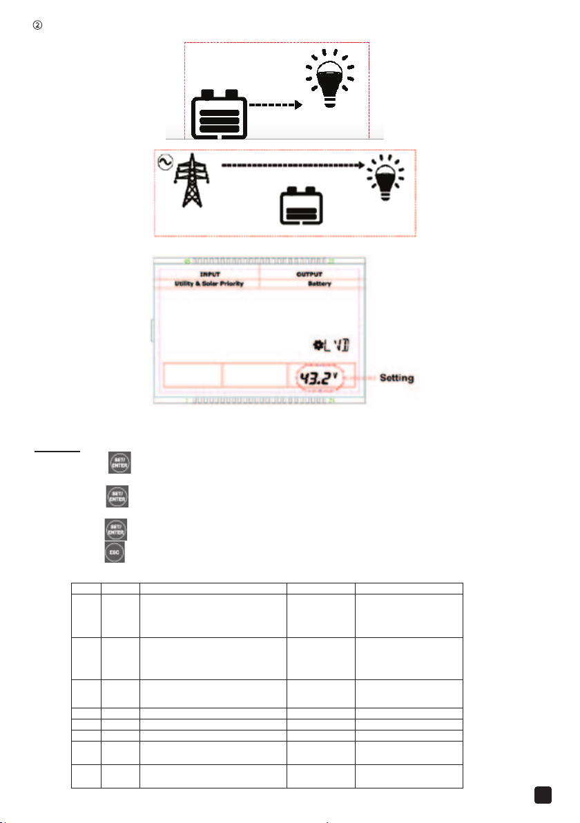
OUT PUT
Item
LCD
Instruction
Default
Range
〜
〜
②
Battery
12
Utility
3.2 Setting Interface
1) Common interface for common user
Operation:
Step 1: Press the button and hold on 5s at the real-time interface to go to the common interface
Step 2: Press the button and hold on 5s at the setting parameter interface and choose the parameters.
Step 3: Press the button to set the parameter, and press this button again for confirmaton.
Step 4: Press the button to exit the setting interface.
Setting
1 BTP Battery type AGM
2 CSP Charge source priority Solar priority
3 OSP Output source priority Battery
4 TMU Temperature unit /
5 BLT Backlight time 30S 30S/60S/100S
6 BAS Buzzer alarm switch ON ON/ OFF
7 LVD Low voltage disconnect voltage
8 LVR Low voltage reconnect voltage
AGM
GEL
FLD
USER
Solar priority
Utility priority
Utility & solar
Solar
Battery
Utility
21.6V
25.0V
User 21.0
step size 0.2V
User 24.0
step size 0.2V
22.6V
26.0V
11
Page 13
The voltage parameter are at 25C, 24VDC system, and twice in 48VDC system.
:
〜
〜
〜
User: 21.6〜24.0VDC
〜
NOTE: When Output source priority is Battery and the battery voltage lower than the Low Voltage Disconnect
Voltage(LVD adjustable), the system will switch utility to supply power for load.
2) Advanced interface for engineers
Operation:
Step1: Press the + button and hold on 5s under the real-time interface.
Step2: Press the button and hold on 5s under the setting parameter interface.
Step3: Press the button to enter the parameter.
Step4: Press the button to exit the setting interface.
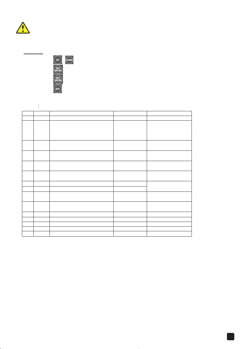
Setting:
Item LCD Instruction Default Range
9 BCT Boost Charging Time 30M 30M/60M/120M/180M
10 BCV Boost Charging Voltage
11 BVR Boost Voltage Reconnect
12 FCV Float Charging Voltage
13 OVR Over Voltage Reconnect Voltage
14 OVD Over Voltage Disconnect Voltage
15 AOF
16 AON
17 DON
18 DOF Dry connect OFF voltage
19 MCC Max. charging current
20 PSM Power saving mode OFF ON/OFF
21 CFA Clear fault OFF ON /OFF
22 QCL Clear the accumulated energy OFF ON/OFF
23 VER Software v ersion U-1.0
The voltage parameter are at 25C 24VDC system (twice in 48VDC system ).
For the inverter/charger of dierent power, the current setting range is not the same, see Technical Parameters
for details.
NOTE
15/16:Stop/restore auxiliary module charging voltage
Only when the charging mode is Solar priority or Utility priority will the auxiliary module charging voltage be
eective.
Auxiliary module OFF voltage
Auxiliary module ON voltage
Dry connect ON voltage
28.8 VDC
AGM
GEL:28.4 VDC
FLD:29.2 VDC
USER:28.8VDC
26.4VDC
27.6 VDC
30.0 VDC
32.0 VDC
28.0VDC
24.0 VDC
22.2 VDC
24.0 VDC
15.0〜60.0A
60.0A
User 25.0〜29.6
Step size 0.2
User: 25.0〜28.0
Step size 0.2
User: 26.0
Step size 0.2VDC
User: 29.0
Step size 0.2VDC
User: 31.0〜32.2VDC
Step size 0.2VDC
User: 24.0
Step size 0.2VDC
Step size 0.2VDC
User: 24.0
Step size 0.2VDC
—
VDC
VDC
VDC
VDC
28.0VDC
31.0VDC
29.6VDC
26.5VDC
20: Power saving mode
When the switch is on “Saving” side, the inverter will enter into the Saving Mode. It will shut o the output if the loads
value is less the 70W. Then restart and detect the power of the load again after 10s. If the load is more than 70W, the
inverter will turn on the output. Otherwise it
if the load is smaller then 70W.
21: Clear the faults
In occurrence of short circuit or overload caused to AC output, the fault can be cleared out.
will shut o output. It cycles like this. So please don’t use the saving mode
12
Page 14
3.5 Other Function
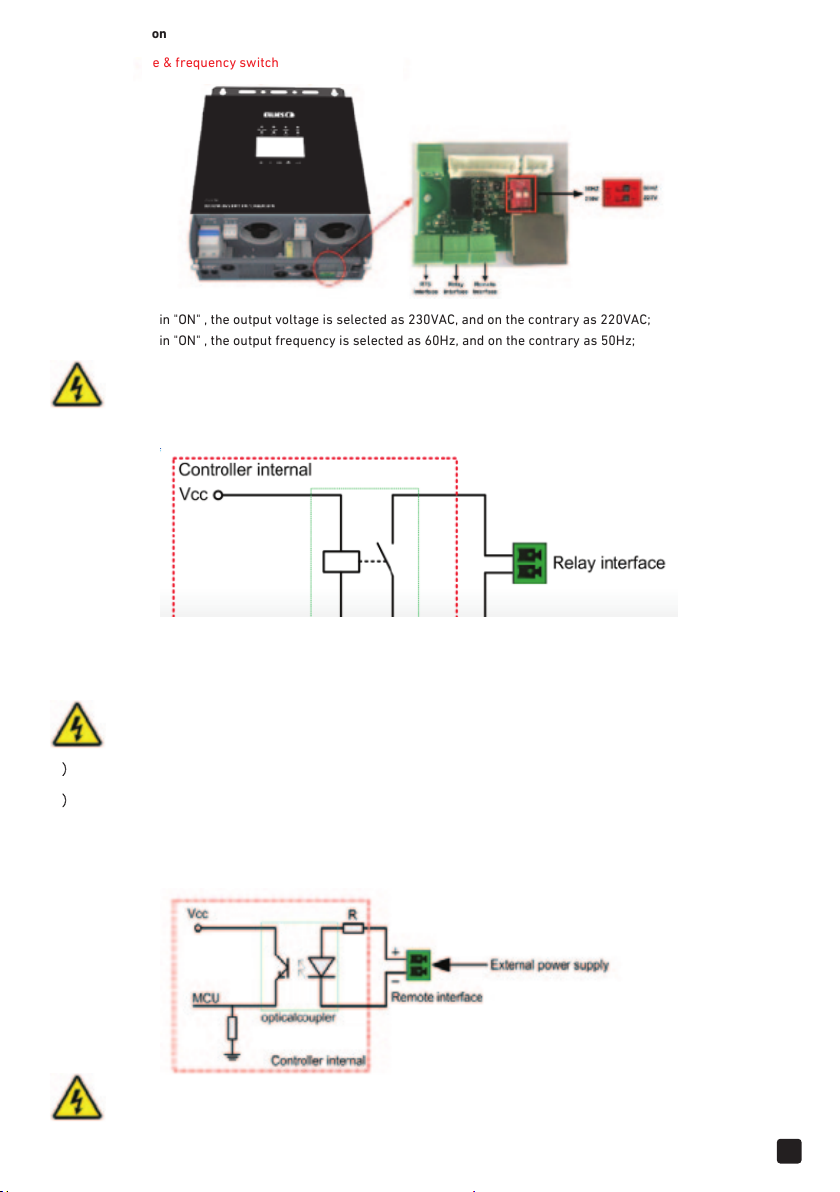
1)) Output voltage & frequency switch
When Switch 1 is in "ON" , the output voltage is selected as 230VAC, and on the contrary as 220VAC;
When Switch 2 is in "ON" , the output frequency is selected as 60Hz, and on the contrary as 50Hz;
NOTE: If the output frequency or voltage of the inverter/charger is to be reset, it is required to turn o the
inverter/charger and power on the unit after setting.
2) Relay interface
Working principle:
When the battery voltage reaches the Low Voltage Disconnect Voltage (LVD)the coil of relay is energized, and the switch is
turned on. The dry contact can drive resistive loads 125VAC /1A, 30VDC/1A.
NOTE: When the utility input is abnormal, this dry contact can control the generator switch to charge the battery.
1)
Remote interface
Remote interface input voltage (3.3 ~ 12V )DC
2)
(1) The input voltage Vi is with in 2.5~ 10s, the AC output state is reversed (when the AC is formerly in output state, now it is
in 2.5~ 10s, thein no-output state; when the AC is formerly in no-output state, now it is in output state;)
(2) The input voltage Vi is greater than 10s, the AC is in output state all the time till the input voltage Vi disappears.
NOTE: If it is to change the range of input voltage, it can be realized by changing the resistance value of R.
13
Page 15
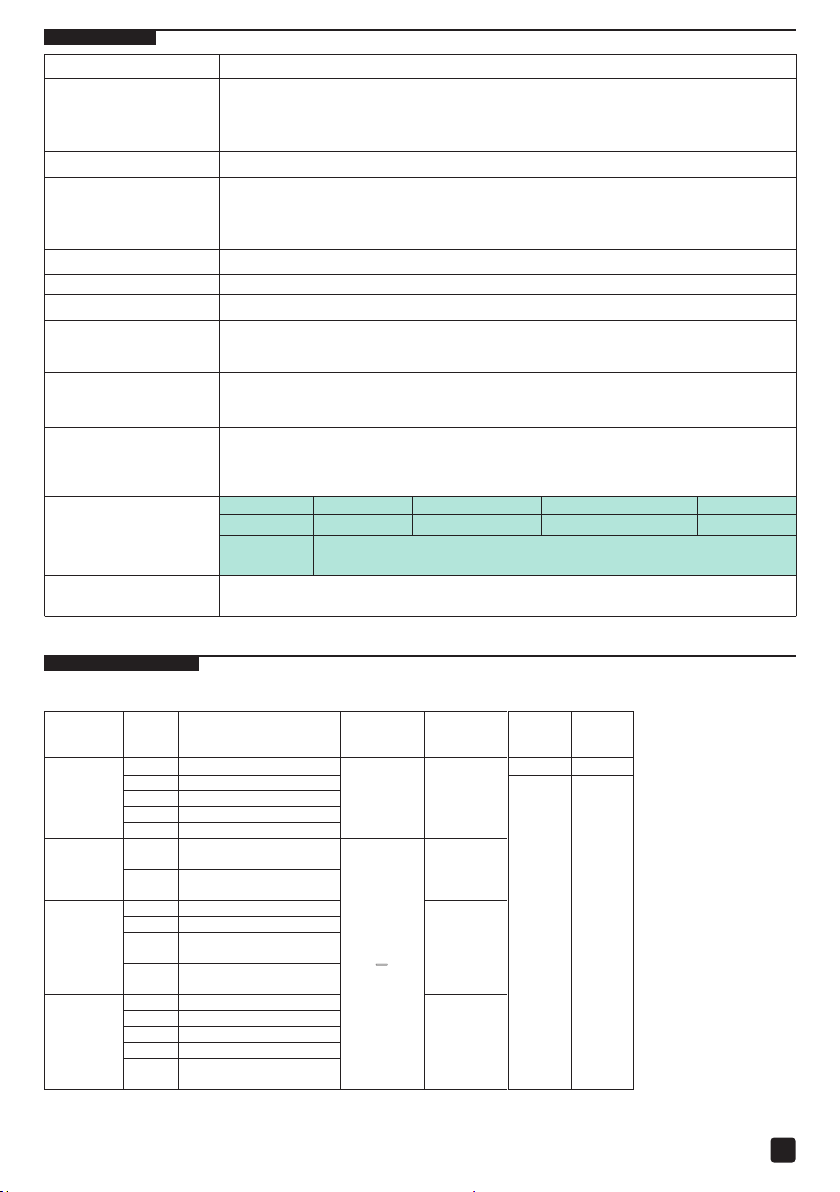
4. Protection
BOD
Battery Over discharge
IOV
Input Over Voltage
ILV
Input Low Voltage
Over Temperature
OVA
Output Over Voltage
IOS
Input Low Voltage
OOL
Output Over Load
OTP
Inverter Temperture
Communication Fault
Protection
PV Limit Current
PV Short Current
PV Reverse Polarity
Night Reverse Charging
Utility Input Overvoltage When the utility voltage exceeds 280VDC, it will stop utility charging/discharging.
Utility Input Under Voltage When the utility voltage less than 160VDC, it will stop utility charging/discharging.
Battery Overvoltage When the battery voltage reaches to the set point of Over Voltage Disconnect Voltage,
Battery Over Discharge When the battery voltage reaches to the set point of Low Voltage Disconnect Voltage, the
Load Output Short Circu
Load Output Overload
Device Overheating
Instruction
When the charging current of the PV array exceeds its rated current, it will be charged at
the rated current. NOTE: When the PV modules are in series, ensure that the open circuit
voltage of the PV array does not exceed the "maximum PV open circuit voltage".
Otherwise the inverter/charger may be damaged.
When PV is not charging and short circuit, the inverter/charger is not damaged.
Fully protection against PV reverse polarity, correct the wire connection to resume normal
operation. NOTE: The inverter/charger will be damaged when the PV array straight polarity
and the actual operation power of the PV array is 1.5 times greater than the rated charge
power!
Prevent the battery discha
the inverter/charger will stop charging the battery to protect the battery from being over
charged to break down.
controller will stop discharging the battery to protect the battery from being over
discharged to break down.
it
It will immediately close the output in occurrence of short-circuit and hereafter the output
is automatically recovered in time delay (the first time delay for 5s, the second time delay
for 10s, the third time delay for 15s); if the short-circuit remains after 3 times of delay,
restart the inverter/charger only after clearing the fault.
Overload 105% 130% 160% 180%
Continuance
Recover 3
times
The inverter/charger will stop charging/discharging when the internal temperature is too
high, and will restore charging/discharging w
15min. 30s 10s 5s
The first time delay for 5s, the second time delay for 10s, the third time
delay for 15s
rging through the PV module in the night.
hen the temperature is recovered to normal.
5. Troubleshooting
5.1 Fault
Module Code Fault
BLV Battery Low Voltage
Battery
PV
charging
module
Utility
charging
module
Inverter
output
module
BOV Battery Over Voltage
NVE Nominal Voltage Error
LTP Low Temperature
OTP
CFA
OTP
CFA
CFA
Over Temperature
(PV Charge Module)
Communication Fault
Alarm
(Utility Charge Module)
Communication Fault
Alarm
Alarm
Battery
frame
blink
Flashing
—
Indicator Buzzer
— —
—
PV charge
Fast
Flashing
Utility
Fast
Flashing
Inverter
Fast
Flashing
Alarm
Fault
indicator
On
Solid
14
Page 16
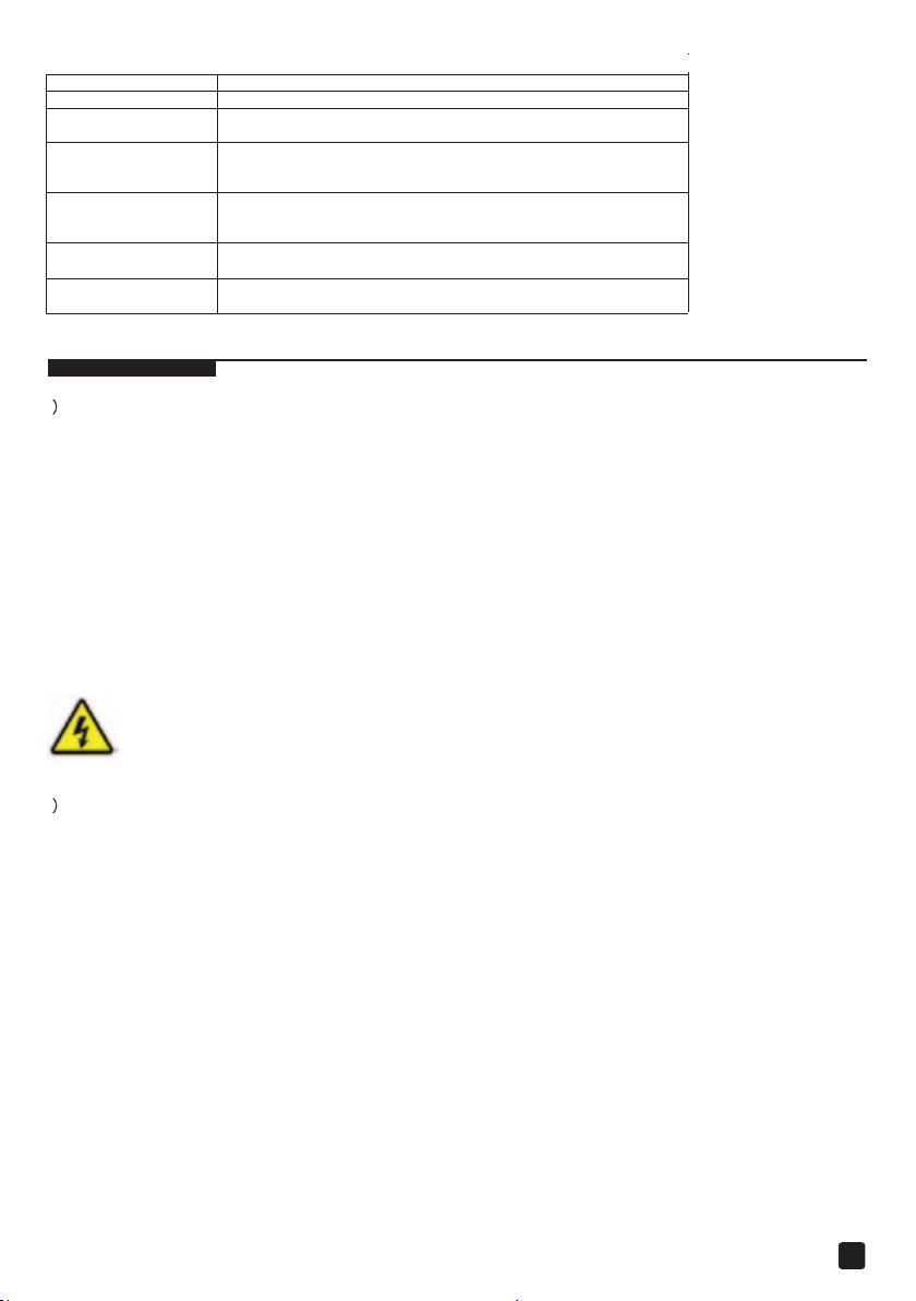
5.3 Troubleshooting
recover temperature value, the inverter/charger will work normally.
Please reduce the number of A
C loads
.
Fault Troubleshooting
Battery Over Voltage Check if battery voltage too high, and disconnect solar modules.
Battery Over Discharge
Battery Overheating
Device Overheating
When the battery voltage resume to or above LVR point (low voltage
reconnect voltage), or change the battery by other ways
The inverter/charger will automatically turn the system o.
But while the battery
recover temperature value, the inverter/charger will work normally.
The inverter/charger will automatically turn the system o.
But while the device
temperature declines
temperature declines
to be below overheating
to be below overheating
Output Overload
Output Short Circuit
②Restart the device or CFA of setting interface change to ON .
Check carefully loads connection, clear the fault.
②Restart the device CFA of setting interface change to ON ..
6. Maintenance
The following inspections and maintenance tasks are recommended at least two times per year for best performance.
1)
• Make sure inverter/charger firmly installed in a clean and dry environment.
• Make sure no block on air-flow around the inverter/charger. Clear up any dirt and fragments on radiator.
• Check all the naked wires to make sure insulation is not damaged for serious solarization, frictional wear, dryness,
insects or rats etc. Repair or replace some wires if necessary.
• Tighten all the terminals. Inspect for loose, broken, or burnt wire connections.
• Check and confirm that LED is consistent with required. Pay attention to any troubleshooting or error indication.
Take corrective action if necessary.
• Confirm that all the system components are ground connected tightly and correctly.
• Confirm that all the terminals have no corrosion, insulation damaged, high temperature or burnt/discolored sign, tighten
terminal screws to the suggested torque.
• Check for dirt, nesting insects and corrosion. If so, clear up in time.
• Check and confirm that lighting arrester is in good condition. Replace a new one in time to avoid damaging of the
inverter/charger and even other equipments.
WARNING: Risk of electric shock! Make sure that all the power is turned o before above operations, and then
follow the corresponding inspections and operations.
This warranty does not apply under the following conditions:
2)
• Damage from improper use or use in an unsuitable environment.
• PV or load current, voltage or power exceeding the rated value of controller.
• The inverter/charger is working temperature exceed the limit working environment temperature.
• User disassembly or attempted repair the inverter/charger without permission.
•The inverter/charger is damaged due to natural elements such as lighting.
•The inverter/charger is damaged during transportation and shipment.
15
Page 17
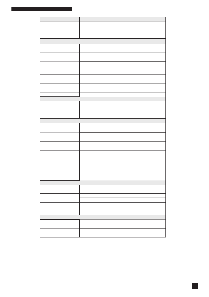
7. Technical Specifications
Voltage Range
O
verload Power(5s
)
4800VA
6000VA
Power Factor
0.8
Distortion THD
≤3%(24V,,4V or 48V Resistive Load)
Inverter Eciency
≤95%
Utility Charge Current
30A
15A
Max. PV Input Power
780W
1040W
Boost Voltage
28.8V
57.6V
Enclosure
IP30
Relative Humidity
< 95%(N.C.)
Working
Mounting Dimension
230mm
Mounting Hole Size
Φ8mm
Product Weight
9.8kg
10.6
kg
Item
System Battery
Voltage
Battery Input
Continuous Output
Power
Output Power (15min.)
Max. Surge Power
Output Voltage
Range
Output Frequency 50HZ/60HZ
Output Wave Pure Sine Wave
Utility Input Voltage
Range
Transfer Time 20mS
Max. PV Open Circuit
Voltage
PV Charging Current 30A 20A
Equalization Voltage
Float Voltage 27.6V 55.2V
Tracking Eciency ≤99.5%
Charging Conversion
Eciency
Temperature
Compensate
Coecient
No Load
Consumption
FBIC3000VA/24V FBIC3000VA/48V
24VDC 48VDC
21.6〜32VDC 43.2〜64VDC
Inverter Output
2400VA
3000VA
220VAC±3%
Utility Input
170VAC 〜275VAC
Solar Charging
150V*
138V*
29.2V 58.4V
≤98%
-3mV/C/2V (Default)
Others
≤0.8A ≤0.6A
Environment
Temperature
Dimension 444×300×126mm
At minimum operating environment temperature
At 25Cenvironment temperature
-20〜 50 (100% Input and Output)
Mechanical Parameters
16
Page 18

NOTES
17
Page 19

NOTES
18
Page 20

South Africa: 0861-ELLIES (355437)
For branch or agent contact details,
please refer to website: www.ellies.co.za
Help Line
 Loading...