

Ellex Medical Tango LT5106-T, Solo LT5106-S, UltraQ LQP3106-U Service Manual

Service
Manual
The information, illustrations, tables, drawings, and specifications in this document are subject to change
without notice.
Ellex®, Tango™, Solo™, Ultra Q™, Total Solution™, and the Ellex logo, are trademarks of Ellex Medical Pty
Ltd.
Teflon™ is a trademark of E. I. du Pont de Nemours and Company, Delaware US.
All other trademarks and copyrights are the property of their respective owners.
This manual describes how to service the Tango (LT5106-T), Solo (LT5106-S) and Ultra Q (LQP3106-U)
ophthalmic lasers. These devices are manufactured in Australia by Ellex Medical Pty Ltd.
Ellex Medical Pty Ltd
82 Gilbert St
Adelaide SA 5000
AUSTRALIA
T +61 8 8104 5200
F +61 8 8104 5231
eservice@ellex.com
www.ellex.com
0805
Ellex Services Europe SARL
108, avenue Marx Dormoy
63000 Clermont-Ferrand
FRANCE
T +33 4 73 34 18 55
F +33 4 73 93 21 98
Copyright © Ellex Medical Pty Ltd 2011. All rights reserved.
This document contains confidential and proprietary information, and may only be reproduced in whole or
in part for use with the device(s) described herein.
Part number 8436015EN-01 ECR 3741

Tango, Solo and Ultra Q Service Manual
Contents
Contents ..........................................................................................................................3
1 Overview..................................................................................................................7
1.1 About this manual ......................................................................................................7
1.2 Who should read this manual .....................................................................................8
1.3 How to provide feedback to Ellex ...............................................................................8
1.4 How this manual is updated .......................................................................................8
1.5 Device description......................................................................................................8
1.5.1 Laser aperture......................................................................................................8
1.5.2 Compliance label..................................................................................................9
1.5.3 Laser safety label .................................................................................................9
1.6 Specifications...........................................................................................................10
1.7 Product history.........................................................................................................10
1.7.1 Software ............................................................................................................10
1.8 Tools and equipment ...............................................................................................13
1.8.1 Burn paper.........................................................................................................13
1.8.2 Alignment jig ......................................................................................................13
1.8.3 Model eye .......................................................................................................... 13
1.9 Routine maintenance ...............................................................................................14
1.9.1 Frequency.......................................................................................................... 14
1.9.2 Maintenance tasks ............................................................................................. 14
1.9.3 Electrical safety test............................................................................................14
2 Safety.................................................................................................................... 15
8436015E
N-01 3

Contents
2.1 Before first use.........................................................................................................15
2.2 Precautions during use.............................................................................................16
2.3 Warnings..................................................................................................................16
2.3.1 Electrical safety ..................................................................................................16
2.3.2 Aiming laser .......................................................................................................16
2.3.3 Treatment laser .................................................................................................. 16
2.3.4 Eye safety ..........................................................................................................17
2.3.5 Reflection........................................................................................................... 17
2.3.6 Fire hazard.........................................................................................................17
2.3.7 Electromagnetic compatibility.............................................................................17
2.3.8 Physical safety ...................................................................................................17
2.3.9 Warning signs ....................................................................................................17
2.4 Safety interlock ........................................................................................................18
2.5 Laser safety monitoring ............................................................................................18
3 Theory of operation ................................................................................................19
3.1 Functional overview.................................................................................................. 19
3.1.1 Laser technology................................................................................................19
3.1.2 Medical advantages ...........................................................................................21
3.1.3 Photodisruption..................................................................................................21
3.1.4 Selective laser trabeculoplasty (SLT)...................................................................23
3.2 General device description .......................................................................................23
3.2.1 Electrical block diagram .....................................................................................23
3.2.2 Optical path block diagram.................................................................................24
3.2.3 Overview............................................................................................................24
3.2.4 Slit lamp............................................................................................................. 24
3.2.5 Delivery head .....................................................................................................25
3.2.6 Console .............................................................................................................28
3.2.7 Start up sequence..............................................................................................29
3.2.8 Firing sequence..................................................................................................30
4 Alignment ..............................................................................................................31
4.1 Overview..................................................................................................................31
4.2 Standard alignment procedure workflow ..................................................................32
4.2.1 Main flowchart....................................................................................................32
4.2.2 YAG alignment path flowchart ............................................................................ 33
4.2.3 SLT alignment path flowchart .............................................................................34
4.3 Standard alignment procedure .................................................................................35
4.3.1 Focussing the eyepieces .................................................................................... 35
4.3.2 Setting the centre of rotation (COR)....................................................................35
4.3.3 Adjusting background focus............................................................................... 36
4.3.4 Aligning the YAG laser........................................................................................38
4.3.5 Adjusting YAG diode aiming module polarisation (YAG DAM)..............................41
4.3.6 Centring aiming beams to the burn (YAG DAM) ..................................................42
4.3.7 Adjusting posterior offset....................................................................................43
4.3.8 Aligning the SLT aiming beam (SLT DAM)...........................................................50
4.3.9 Centring the SLT treatment beam.......................................................................52
4.3.10 Focussing the SLT aiming beam (SLT DAM).......................................................53
4.3.11 Aligning the slits .................................................................................................54
4.4 Other alignment procedures .....................................................................................56
4.4.1 Aligning the SLT steering mirror (far field alignment) ............................................56
5 Calibration .............................................................................................................57
4
8436015EN-01

Tango, Solo and Ultra Q Service Manual
5.1 Overview..................................................................................................................57
5.2 Standard calibration procedure flowchart .................................................................58
5.3 Energy definitions.....................................................................................................59
5.4 Standard calibration procedure ................................................................................60
5.4.1 Voltage window test...........................................................................................60
5.4.2 YAG diode aiming module (YAG DAM) ...............................................................61
5.4.3 YAG energy monitor........................................................................................... 62
5.4.4 YAG energy prediction .......................................................................................63
5.4.5 SLT diode aiming module (SLT DAM) .................................................................64
5.4.6 SLT energy monitor............................................................................................65
5.4.7 SLT energy prediction ........................................................................................66
5.5 Other calibration procedures ....................................................................................67
5.5.1 KTP crystal energy ............................................................................................. 67
6 Troubleshooting ..................................................................................................... 71
6.1 Service and Engineering modes ...............................................................................71
6.1.1 Service mode.....................................................................................................71
6.1.2 Engineering mode ..............................................................................................72
6.1.3 Display...............................................................................................................73
6.1.4 Menu options.....................................................................................................75
6.2 Error codes .............................................................................................................. 78
6.3 Error messages........................................................................................................79
6.4 Energy warnings and errors...................................................................................... 80
6.5 Cavity performance ..................................................................................................81
6.5.1 Check burn pattern ............................................................................................ 81
6.5.2 Energy stability checks.......................................................................................82
6.5.3 Air breakdown test .............................................................................................83
7 Replacement instructions........................................................................................85
7.1 Spare parts .............................................................................................................. 85
7.2 Electro-static safety procedures ...............................................................................86
7.3 Device reassembly ...................................................................................................86
7.4 Module identification ................................................................................................86
7.4.1 Delivery head .....................................................................................................87
7.4.2 Console .............................................................................................................91
7.4.3 Other items ........................................................................................................ 92
7.5 How to access modules........................................................................................... 93
7.5.1 Delivery head modules .......................................................................................93
7.5.2 SLT delivery carriage ..........................................................................................94
7.5.3 Console modules ...............................................................................................96
7.6 How to remove the delivery head and slit lamp.........................................................97
7.6.1 Delivery head .....................................................................................................97
7.6.2 Slit lamp............................................................................................................. 98
7.7 Attenuator (SLT) ....................................................................................................... 99
7.8 Attenuator (YAG) ....................................................................................................100
7.9 Beam expanding telescope (BET)...........................................................................102
7.10 Delivery head cable................................................................................................103
7.11 Diode aiming module (SLT DAM) ............................................................................107
7.12 Diode aiming module (YAG DAM) ........................................................................... 108
7.13 Dimmer module .....................................................................................................110
7.14 Emergency stop switch.......................................................................................... 112
7.15 Fire control board...................................................................................................113
8436015E
N-01 5

Contents
7.16 Fixation lamp..........................................................................................................115
7.17 Folding mirror (YAG)...............................................................................................116
7.18 Interlock board....................................................................................................... 117
7.19 Joystick .................................................................................................................118
7.20 Keyswitch ..............................................................................................................122
7.21 Laser power switch................................................................................................123
7.22 Objective lens.........................................................................................................124
7.23 Power indicator......................................................................................................125
7.24 Power supply (DC) .................................................................................................126
7.25 Power supply (YAG) ............................................................................................... 127
7.26 Prism tower............................................................................................................129
7.27 Safety filter.............................................................................................................130
7.28 SLT delivery carriage..............................................................................................131
7.29 Trigger (see YAG laser cavity).................................................................................131
7.30 YAG laser cavity..................................................................................................... 132
8 Schematics.......................................................................................................... 135
6 8436015EN-01

Tango, Solo and Ultra Q Service Manual
1 Overview
1.1 About this manual
This manual describes how to service the:
Solo 532 nm (SLT) pulsed green laser
Tango 532 nm (SLT) green and 1064 nm (YAG) pulsed infrared laser
Ultra Q 1064 nm (YAG) pulsed infrared laser
These devices are classified as Class 3B lasers, with Class 1 Type B electrical protection. They are
surgical laser instruments designed for use by ophthalmologists in clinics, or an outpatient facility in
a hospital or surgery.
The Ultra Q may be upgraded to a Tango (Japan and US excluded). Contact Ellex Global Service
for further details.
Instructions are provided based on the most recently manufactured versions of these laser
products. Reference to older components, where appropriate, will be made where these deviate
significantly from current production.
Illustrations used in this manual are based on a Tango. The illustrations may contain callouts,
including a dashed arrow pointing to a dashed circle: this highlights the item(s) mentioned (for
example, screws to be loosened or removed) in the instruction. An illustration number (for example,
sm_tsu_0051) is included for writing purposes only.
8436015E
N-01 7
Overview
1.2 Who should read this manual
This manual assumes that you are a fully trained and qualified Ellex Service Technician, with
access to the appropriate Ellex Service Toolkit(s).
1.3 How to provide feedback to Ellex
Ellex welcomes your feedback on the accuracy and effectiveness of this document. Please send
feedback to Ellex Global Service (eservice@ellex.com). Ensure that the document name and part
number (see the footer of each page) are clearly identified, and refer to page number(s) where
appropriate.
1.4 How this manual is updated
Ellex Service Bulletins released since the publication date of this manual may provide corrections or
updates to this issue of the service manual.
1.5 Device description
Refer to the user documentation supplied with the device.
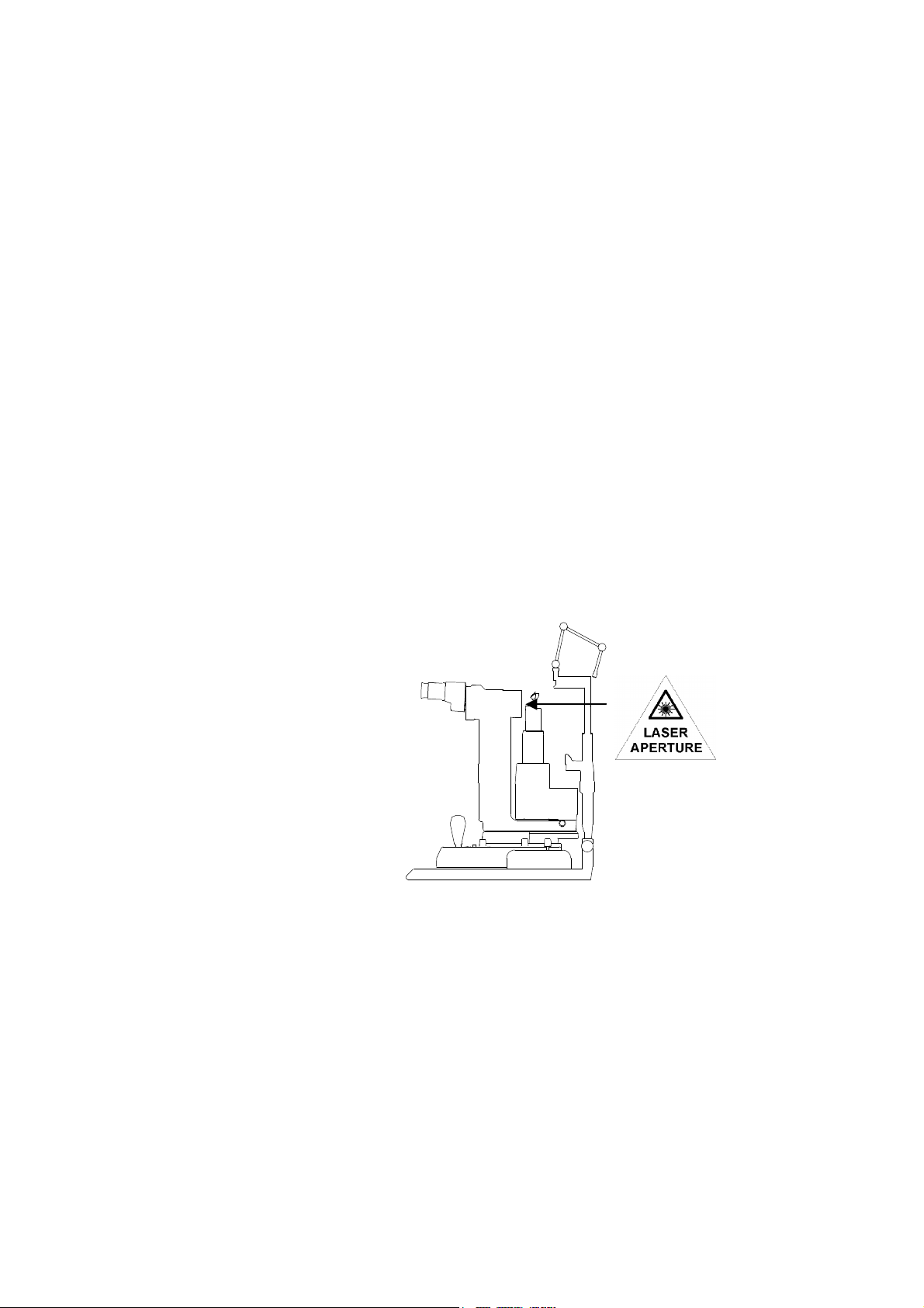
1.5.1 Laser aperture
The location of the laser aperture is shown below. The laser aperture label is placed immediately
below the aperture
sm_tsu_0076
8
8436015EN-01
1.5.2 Compliance label
REF
SN
0805
Tango, Solo and Ultra Q Service Manual
Manufacturer
Device model designation (Solo: LT5106-S, Tango: LT5106-T, Ultra Q: LQP3106-U)
Serial number
Date of manufacture
Recycling symbol
Reminds the user to use recycling methods when disposing of this product
Type B equipment symbol
The equipment provides protection against electric shock through the limiting of leakage
current and the provision of a protective earth connection.
Pollution control label in compliance with PRC standards
CE mark in compliance with the EU Medical Device Directive (MDD)
The user must read and comprehend the user documentation before use
1.5.3 Laser safety label
Solo (LT5106-S)
Tango (LT5105-T)
8436015E
N-01 9

Overview
Ultra Q (LQP3106-U)
1.6 Specifications
Refer to the user documentation supplied with the device.
1.7 Product history
1.7.1 Software
Release numbering for the Tango and Ultra Q is separate from Solo software releases.
Tango and Ultra Q
Version 5
Released 22 June 2009
Technical Bulletin No. TB-09-01 (latest)
Upgrade Details Optional for systems prior to S/N TG0989 (and UQ0641). An upgrade kit is available from
www.ellex.com.
User related changes As documented in User Guide Amendment No. 8.
Service related changes Voltage window test Now performed with the attenuator in the 100% open transmission position
for consistency.
Previous version based the single, double and triple pulse voltages on
50%, 60% and 60% (respectively) of the voltage window.
To reduce the possibility of over-pulsing, the voltage is now calculated
using 40% for single, double and triple pulse voltages.
Automatic under
and over-pulse
correction
Power up self test Test fires are now performed at a slightly elevated voltage to induce and
Previously, if an under or over-pulse was detected only an error was
reported.
The follow actions now take place if an under or over-pulse is detected.
Over-pulse
Emits a warning and device reverts to STANDBY
Voltage is reduced
Test fire occurs at the new voltage to verify pulses
If four over-pulses are detected after repeated over-pulse
correction attempts, an EO4 error displays
Under-pulse
Emits a warning and device reverts to STANDBY
Voltage is reduced
Test fire occurs at the new voltage to verify pulses
If four under-pulses are detected, an x800 error displays
E8108 displays if the voltage rises to the maximum allowable
test for any over-pulsing, and allow the device to compensate after
repeated under-pulse correction attempts.
10
8436015EN-01

Tango, Solo and Ultra Q Service Manual
Improved
Energy monitor
DAM calibration DAM set point is recalled at the start of DAM calibration, rather then
E10-S (Tango only) E10-S was displayed if the pulse detector sensed a fault in
Energy
half-wave
plate positioning
calibration
measurement
The attenuator is moved to the zero position and then to the new position
every time the energy is changed by the operator.
This provides more consistent positioning of the half-wave plate and is
noticeable when adjusting the YAG and SLT ZERO value.
Energy monitor set points are recalled during calibration.
resetting to 0.
SLT mode. The fault is now corrected reported as E10-Y, as the fault is in
the YAG attenuator.
Measured energy from the internal test fire is now used as a basis for any
energy change.
Previously, the predicted (or set) value was used.
Version 6
Version 6 was not released (internal Ellex use only).
Version 7
Released 29 June 2010
Technical Bulletin No. TB-10-01 (latest)
Upgrade Details Optional for systems prior to S/N TG1300 (and UQ0800). An upgrade kit is available from
www.ellex.com.
User related changes None
Service related changes Energy prediction Based on customer feedback, energy prediction algorithm as used in V4
software has been reinstated.
Checksum error on
start up
V5 software introduced the automatic over-pulse and under-pulse
correction function. Unfortunately, if an under or over-pulse correction
occurred during the start up tests, the checksum was only updated at the
end of the test sequence, so if the system was powered off after the
software had performed an over or under-pulse correction during the start
up tests, the checksum would be invalid and a checksum failure of
EEPROM error would occur (refer to 6.3 Error messages on page 79). This
issue is
resolved in Version 7 by updating the checksum immediately after
the voltages are updated when the software performs the over or underpulse correction during the start up test.
8436015E
N-01 11

Overview
Solo
Version 6
Released 22 June 2009
Technical Bulletin No. TB-09-02 (latest)
Upgrade Details Optional for systems prior to S/N SL0400. An upgrade kit is available from www.ellex.com.
User related changes As documented in User Guide Amendment No. 8.
Service related changes Voltage window test Now performed with the attenuator in the 100% open transmission position
for consistency.
Previous version based the single, double and triple pulse voltages on
50%, 60% and 60% (respectively) of the voltage window.
To reduce the possibility of over pulsing, the voltage is now calculated
using 40% for single, double and triple pulse voltages.
Automatic under
and over-pulse
correction
Power up self test Test fires are now performed at a slightly elevated voltage to induce and
Energy monitor
calibration
Previously, if an under or over-pulse was detected only an error was
reported.
The follow actions now take place if an under or over-pulse is detected.
Over-pulse
Emits a warning and device reverts to STANDBY
Voltage in use is reduced
Test fire occurs at the new voltage to verify pulses
If four over-pulses are detected after four repeated over-pulse
correction attempts, an EO4 error displays
Under-pulse
Emits a warning and device reverts to STANDBY
Voltage in use is reduced
Test fire occurs at the new voltage to verify pulses
If four under-pulses are detected after four repeated under pulse correction attempts, an x800 error displays
E8108 displays if the voltage rises to the maximum allowable
test for any over-pulsing, and allow the device to compensate.
Lower calibration point is now 10% of maximum energy (previously it was
5%).
12
8436015EN-01

1.8 Tools and equipment
To service these SLT and YAG devices, you require the following items:
Tango/Ultra Q/Solo/Super Q Service Toolkit.
A calibrated laser power/energy meter that must be traceable to the US National Institute of
Standards and Technology (NIST), or other international standard. It must be able to measure
the full laser power/energy range at the treatment and aiming beam wavelength(s) that these
devices emit.
1.8.1 Burn paper
Burn paper is used to check alignment and must be conditioned before use.
To condition burn paper
1 Tear off a strip of burn paper from the roll.
2 Expose the strip in normal office light conditions for 15 minutes before use (or under
intense light or sunlight to hasten the process).
The paper is ready when it changes from pink to grey.
Tango, Solo and Ultra Q Service Manual
1.8.2 Alignment jig
The alignment jig includes a target plate. One side of the plate is covered in matt black insulating
tape and the other side is bare.
Use double sided tape to attach conditioned burn paper to the bare side of the target plate.
Carefully apply and trim the tape to ensure a flat surface before attaching the burn paper.
1.8.3 Model eye
A model eye is used to check optical alignment.
To prepare a model eye
1 Remove the membrane holder from the model eye.
2 Stretch the membrane of a new capsule onto the holder.
Ensure that the rubber ring of the capsule faces to the front.
3 Fill the model eye with sterile or distilled water.
4 Place the membrane holder in the model eye.
The membrane becomes translucent in water.
5 Replace the membrane when it becomes cloudy (after approximately 30 minutes).
8436015E
N-01 13
Overview
Membrane
holder
Rubber ring
Membrane
1.9 Routine maintenance
1.9.1 Frequency
The Tango, Solo and Ultra Q should be routinely serviced every 12 months.
1.9.2 Maintenance tasks
The Product Acceptance and Fault report (PAF) describes the routine service and maintenance
tasks. PAFs are available from Ellex Global Service.
In addition, always clean the device (see the maintenance instructions in the user documentation).
1.9.3 Electrical safety test
To check ground resistance
1 Use a multimeter to check the resistance between the earth pin of the mains socket on
the instrument, and any metal part of the table or console that is protectively earthed.
2 Check the resistance between the earth pin of the mains socket on the instrument and
the slit lamp.
sm_tsu_0001
Ground resistance should not exceed 0.1 Ω at any point.
14 8436015EN-01

Tango, Solo and Ultra Q Service Manual
2 Safety
The content of this chapter is common to the service and operator manuals for all major Ellex laser
devices. Be aware that some information may not apply to the Ellex device that you have
purchased.
Only fully trained and qualified physicians may operate this device.
WARNING! Use of controls or adjustments, or performance of procedures other than those specified in the user
documentation may result in hazardous radiation exposure.
WARNING! This device is designed for use with a range of Ellex approved attachments. The use of non-approved
attachments may result in serious injury to the patient and/or physician and voids the warranty. In no event shall
Ellex, its employees, officers, directors, representatives or affiliates, be held liable for any injury occurring through
such use.
This device is a safe instrument when used correctly. However, like all laser surgical equipment, it
can cause injury if not used in accordance with the correct safety procedures and operating
instructions.
2.1 Before first use
Read this document in its entirety before using the device for the first time.
Ensure that the equipment is correctly installed and that all safety devices are operational.
Anyone likely to use or assist in the use of the device should read this document, and undertake
basic laser safety training. You should designate a laser safety officer to be responsible for
coordinating laser safety
8436015E
N-01 15

Safety
2.2 Precautions during use
Follow these precautions when you use the device:
Do not operate the laser unless it is correctly positioned on a level, stable surface.
Do not adjust or change settings when the laser is fired.
Remove the key from the console when the laser is not in use, to protect the device from
unqualified use.
Do not operate the laser unless the eye safety filter is in place in the delivery device.
Carefully handle optical fibres and delivery systems, and regularly inspect them for damage.
Ensure that delivery devices and optical fibres are correctly connected before using the
device.
Regularly inspect the safety filter.
2.3 Warnings
WARNING! Do not operate the device until you are familiar with all the precautions.
WARNING! Do not use the device if you experience an abnormal operating condition. Contact your Authorised Ellex
Distributor.
2.3.1 Electrical safety
WARNING! To ensure adequate electrical safety, you must connect this device to a mains power outlet that has a
reliable protective earth conductor.
WARNING! To protectively earth the device, the power lead from the mains power outlet to this device must
incorporate an earth terminal and earth conductor.
2.3.2 Aiming laser
WARNING! Do not fire the laser if you cannot see the aiming beam(s).
WARNING! Do not look into the aiming beam(s) unless under the control of a qualified physician.
Refer to the specifications listed in the user documentation for details of the aiming laser.
The blink reflex is considered sufficient protection from the aiming laser. Take precautions to
protect people whose normal aversion responses are impaired or disabled.
Check the aiming beam spot shape regularly to ensure that the device is aligned, and to verify that
the optical fibre is not damaged.
Always use the lowest practical aiming beam intensity, and minimise exposure time.
2.3.3 Treatment laser
16
WARNING! Do not look into the treatment beam unless under the control of a qualified physician.
Refer to the specifications listed in the user documentation for treatment laser details.
A safety shutter blocks the optical path until you fire the treatment laser. A sensor monitors the
shutter and if the shutter fails, the fire switch is disabled and an error code displays.
8436015EN-01

2.3.4 Eye safety
Everyone attending the procedure (except the physician and patient) must wear safety glasses,
goggles or masks designed to prevent transmission of the treatment beam. Safety glasses of
optical density (OD) 5 (minimum) are required for the treatment wavelength.
Appropriate safety glasses should be made available close to the door outside the treatment room.
WARNING! Safety glasses, or safety filters providing protection from other wavelengths, may not offer any
protection from the treatment wavelength and should not be used. Ordinary spectacles offer no protection.
(Europe) Safety eyewear must have a protection class of L5 to meet the EN 207 specification.
Cover any windows and viewing ports in the room while the device is in use.
2.3.5 Reflection
WARNING! Objects that reflect visible light will reflect treatment laser light. Avoid placing reflective materials such
as glass, metal and polished plastic in the path of the laser beam.
All surfaces in the room should be matt finished to prevent possible reflection of the treatment
laser. Avoid using reflective instruments.
Tango, Solo and Ultra Q Service Manual
2.3.6 Fire hazard
WARNING! Some materials (for example, cotton wool saturated with oxygen) may be ignited by the high
temperatures produced by the treatment laser. Before using the device, allow the solutions of adhesives and
flammable solutions (used for cleaning and disinfecting) to evaporate.
WARNING! Ignition of endogenous gases may occur.
2.3.7 Electromagnetic compatibility
Radio frequency sources (for example, mobile phones) may affect the device. Make sure that all
mobile phones in the treatment room are turned off while the device is in use.
2.3.8 Physical safety
WARNING! Do not use the device unless you understand the potential hazards inherent in laser technology.
WARNING! Do not place your hands, arms, or any other body parts or tissue in the path of the treatment laser.
2.3.9 Warning signs
You should display safety signs outside the treatment room warning of the type of laser being
used. Consider installing warning lamps outside the treatment room to indicate that a laser is in
operation.
8436015E
N-01 17

Safety
2.4 Safety interlock
A safety interlock connection is provided for connection to a theatre or clinic door. When
connected, if the door is opened:
the treatment laser is immediately disabled, and the device is placed in STANDBY
a warning sounds
an interlock warning icon is displayed.
A separate fibre interlock detects the presence of an optical fibre connection. The treatment laser
is disabled if an optical fibre is not connected.
2.5 Laser safety monitoring
A hardware safety system monitors the power and safety functions of the device, and ensures that
software failure does not affect the safety of the device.
18 8436015EN-01

Tango, Solo and Ultra Q Service Manual
3 Theory of operation
3.1 Functional overview
3.1.1 Laser technology
Laser is an acronym for
In its most basic form, a laser is a device that converts electrical energy to light. The conversion
efficiency is quite low (of the order of 1–4%), but the light that is produced is quite different from
other sources, such as fluorescent tubes or the sun. The differences are:
Coherence—all the waves are exactly in phase, with no interference between waves, so there
is no loss of energy.
Monochromaticity—the range of wavelengths or energies present is extremely small.
Wavelength—all other sources of light or heat have a broad range of energy (or wavelengths).
Since lasers have a narrow range, a beam can be selected with a wavelength well matched
to the absorption properties of the tissue of interest.
Collimation—the beam does not diverge, it can travel a long way, while maintaining a small
spot size.
light amplification by stimulated emission of radiation
.
8436015E
N-01 19
Theory of operation
Stimulated emission
The laser beam is produced by the process of stimulated emission. During this process, atoms are
excited above their ground state by an energy source (a flash lamp in the Tango, Solo and Ultra Q).
When the excited atoms return to their ground state, they emit photons, which are reflected by
mirrors back and forth through the laser medium within the laser cavity.
When a photon hits an already excited atom in the laser medium, the atom emits another photon.
This means that one photon enters and two leave, both in the same direction as that of the
incoming photon, and both with exactly the same phase in relation to each other (coherent), and at
the same wavelength.
Elements of a laser
A laser has three major components:
laser medium—a solid, liquid or gas, where the energy from the source is absorbed, and
photons are emitted
energy source or pump—such as a flash lamp
resonant laser cavity—in which the photons are reflected back and forth, producing pulses of
laser light.
Laser medium
The laser (or lasing) medium is a solid-state crystal of neodymium-doped yttrium aluminium garnet
(Nd:YAG).
Energy source (or pump)
The energy source is a flash lamp containing a gas that can be ionised. It receives pulses of
electrical energy, which are conducted by the ionised gas, causing a discharge of high voltage
energy. The energy is released as a bright flash of white light. The laser medium absorbs and reemits certain wavelengths, forming the laser beam by the process of stimulated emission.
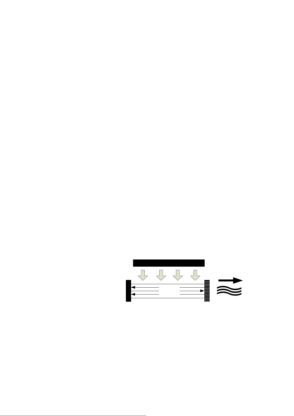
Laser cavity
The cavity contains the flash lamp, the laser medium, and a series of totally and partially reflective
mirrors that reflect the photons and allow a polarised beam of laser light to exit.
Flash lamp
Output
Resonator
Totally Reflective
Mirror
Partially Reflective
Mirror
sm_tsu_0002
20
Pulsed operation (Q-switching)
A pulsed mode of operation, commonly called Q-switching, is used. In this system, a component
called a Q-switch is added to the laser system to cause the laser to produce a short pulse (on the
order of a few nanoseconds) each time the laser is fired.
The Q-switch can produce a number of laser pulses for a single firing of the flash lamp. The
number of pulses emitted is proportional to the energy input to the flash lamp, which is provided by
a high voltage capacitor charging power supply.
8436015EN-01
Tango, Solo and Ultra Q Service Manual
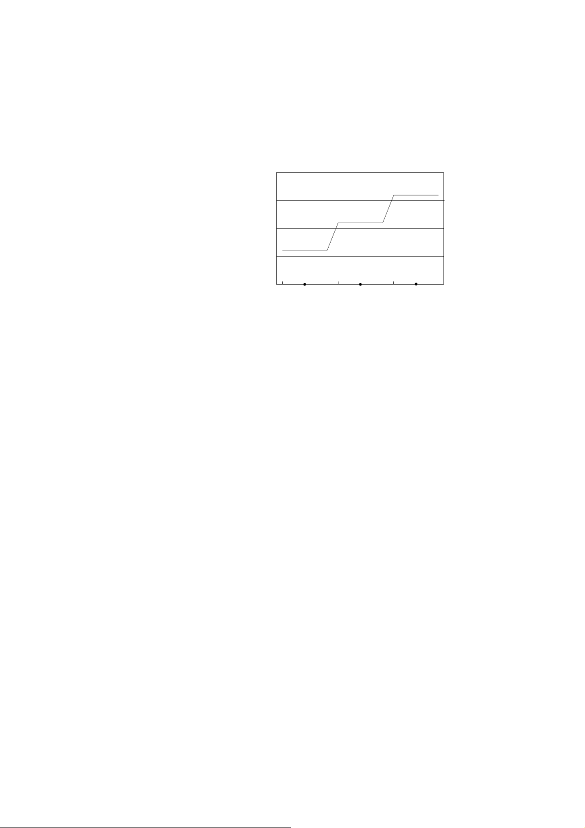
The main discharge capacitor is a 64 µF (microfarad) 900 V pulsed type. The energy entering the
flash lamp is proportional to the square of the capacitor voltage characteristic (as shown in the
illustration below) which shows flash lamp voltage versus Nd:YAG energy output. It is important
that when the laser is in operation, the voltage to the flash lamp must be set correctly to prevent
the possibility of too few or too many pulses.
Flash Lamp Voltage vs Laser Energy Output
40
30
20
10
Laser Engery (mJ)
General reference only
3.1.2 Medical advantages
For medical use, the differences between laser light and other sources offer the following major
advantages in their clinical applications:
significantly higher power densities at the target tissue
ability to match the wavelength to the absorption properties of the tissue of interest for a
desired effect
ease of focusing a parallel beam to small spot size.
These same properties also give laser radiation a greater potential to cause injury than light from
other sources.
Like all Nd:YAG ophthalmic laser surgery, there are risks involved, and use of the YAG or SLT
treatment lasers may be contraindicated for patients with certain pre-existing ocular pathologies.
Objective assessment of candidate patients for each procedure must be done in light of the risks,
which are discussed in detail in the documentation supplied with the instrument.
3.1.3 Photodisruption
The YAG treatment beam operates by photodisruption. The energy of the pulses produced by the
laser is adjustable, and the energy density at the focal point is sufficient to create a small ionisation
site (plasma) in the vitreous cavity. The plasma produces an acoustic wave that radiates from the
focal point and ruptures, or disrupts, adjacent tissue. This is known as the
The YAG treatment beam is intended for dissection of the posterior capsule of the eye (posterior
capsulotomy), dissection of the pupillary membrane of the eye (posterior membranectomy), as well
as other surgical procedures such as iridotomy (opening a hole in the iris). Unlike other lasers
commonly used in ophthalmology (such as argon, krypton and ruby laser coagulators), Ellex
photodisruptors do not rely on thermal effects.
A visible red diode dual spot laser is used to aim the treatment beam. The dual aiming beams are
coaxial with the treatment beam, and the laser is focused when the two aiming beams converge to
form a spot. This low power diode laser light is set to focus at the same plane as the slit lamp
(parfocal with the slit lamp).
Single Pulse
431
Double Pulse
493
Flash Lamp Voltage (V)
544
Triple Pulse
sm_tsu_0003
photodisruptive effect
.
8436015E
N-01 21
Theory of operation
Photodisruptive effect
The YAG laser is focussed to an 8 µm spot which produces a small ionisation site (plasma) at the
focal point. The resulting plasma formation produces an acoustic wave that disrupts nearby tissue
in a process known as the
The plasma absorbs and scatters further incident light, and this shields the underlying structures
from damage. The beam divergence after the focal point also protects the retina from damage that
could otherwise occur by the absorption of concentrated Nd:YAG treatment energy.
As the treatment energy increases, the size of the plasma formed also increases, which causes a
larger, stronger acoustic wave. To avoid the possibility of the plasma damaging the intraocular lens
(IOL) by causing cracking, pitting or chipping, and to allow the accompanying shock wave to be
most effective, the treatment beam may be offset further behind the membrane to be penetrated
(posterior to the focal plane of the slit lamp, which is focused on the membrane). A posterior offset
control allows selection of the amount of offset required.
The energy of the laser pulse(s) is continuously adjustable and is normally set at the lowest
possible effective level to minimise unwanted side effects.
photodisruptive effect
.
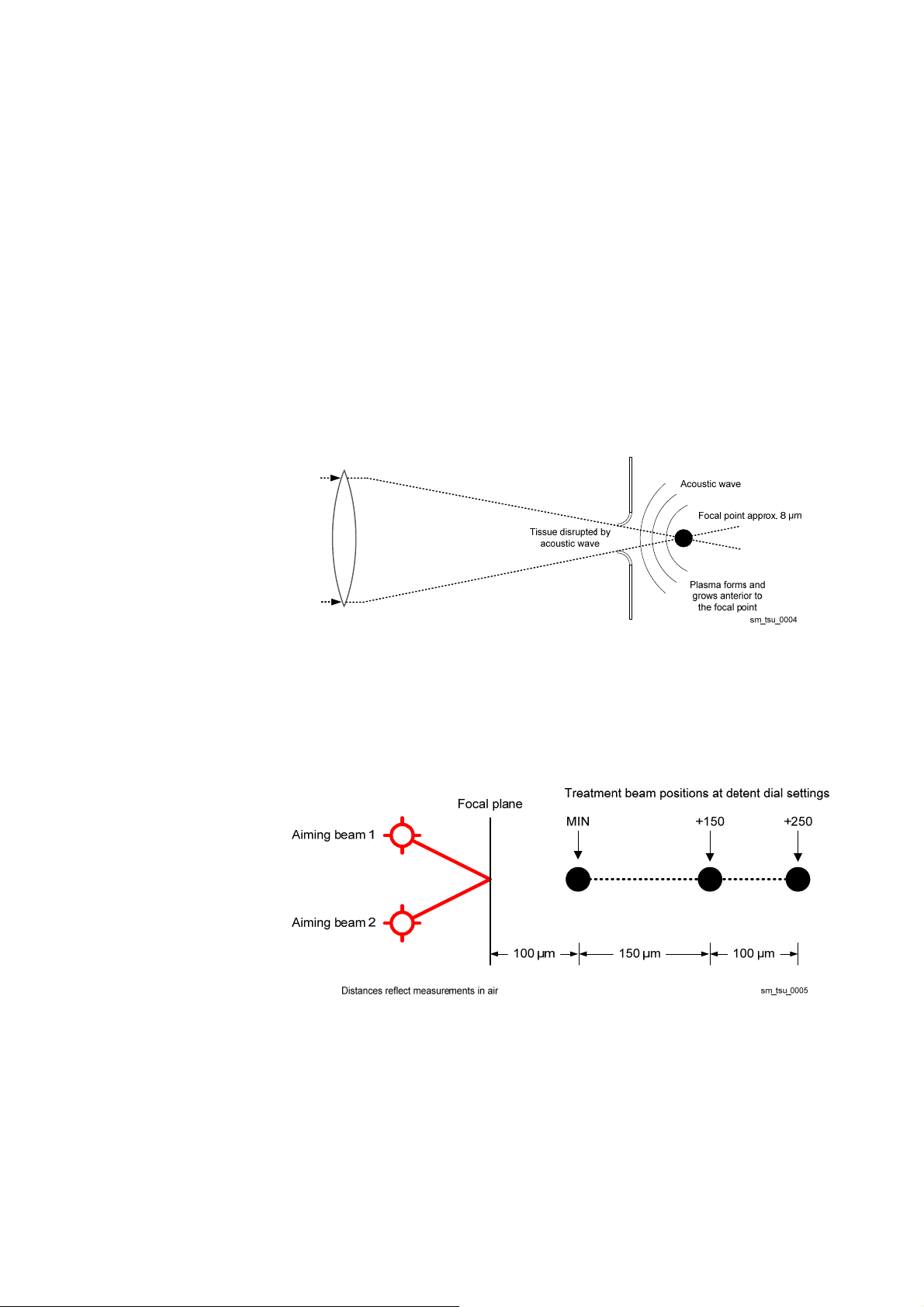
YAG posterior offset
The Tango and Ultra Q (the Solo has only the SLT treatment beam) have an adjustable posterior
offset from 100 µm to 250 µm between the treatment laser focus and aiming beams (illustrated
below). This offset is adjusted using the posterior offset control on the delivery head. The normal
initial setting is 150 µm.
22
8436015EN-01
3.1.4 Selective laser trabeculoplasty (SLT)
The Tango and Solo have an SLT treatment beam (the Ultra Q has only the YAG treatment beam,
but may be upgraded to include an SLT treatment beam).
The SLT treatment beam is used to reduce intraocular pressure by selectively targeting the
pigmented within the trabecular meshwork.
A single visible red diode single spot laser is used to aim the treatment laser beam. The aiming
beam is coaxial with the treatment beam and has a fixed focus.
Laser pulses are accurately positioned using a coaxial aiming beam, and a gonioscopy contact
lens, which is fitted to the patient’s eye. The 532 nm wavelength is absorbed more readily by the
pigmented cells, causing them to be destroyed but leaving the trabecular support structure intact.
The low power diode laser light is set to focus at the same plane as the slit lamp (parfocal with the
slit lamp).
3.2 General device description
The block diagrams below are provided to help you understand the main components of the
device. They do not accurately indicate the exact layout.
Tango, Solo and Ultra Q Service Manual
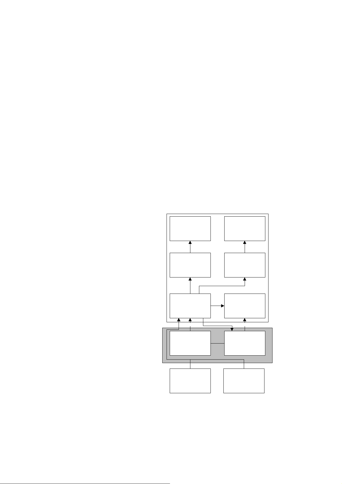
3.2.1 Electrical block diagram
This is an overview of the electrical connections between the major modules.
Delivery
head
Console
YAG attenuatorSLT attenuator
Fire control board
DC HV
DC PSU YAG PSU
YAG DAMSLT DAM
Trigger
8436015E
External
N-01 23
Remote control Footswitch
sm_tsu_0006
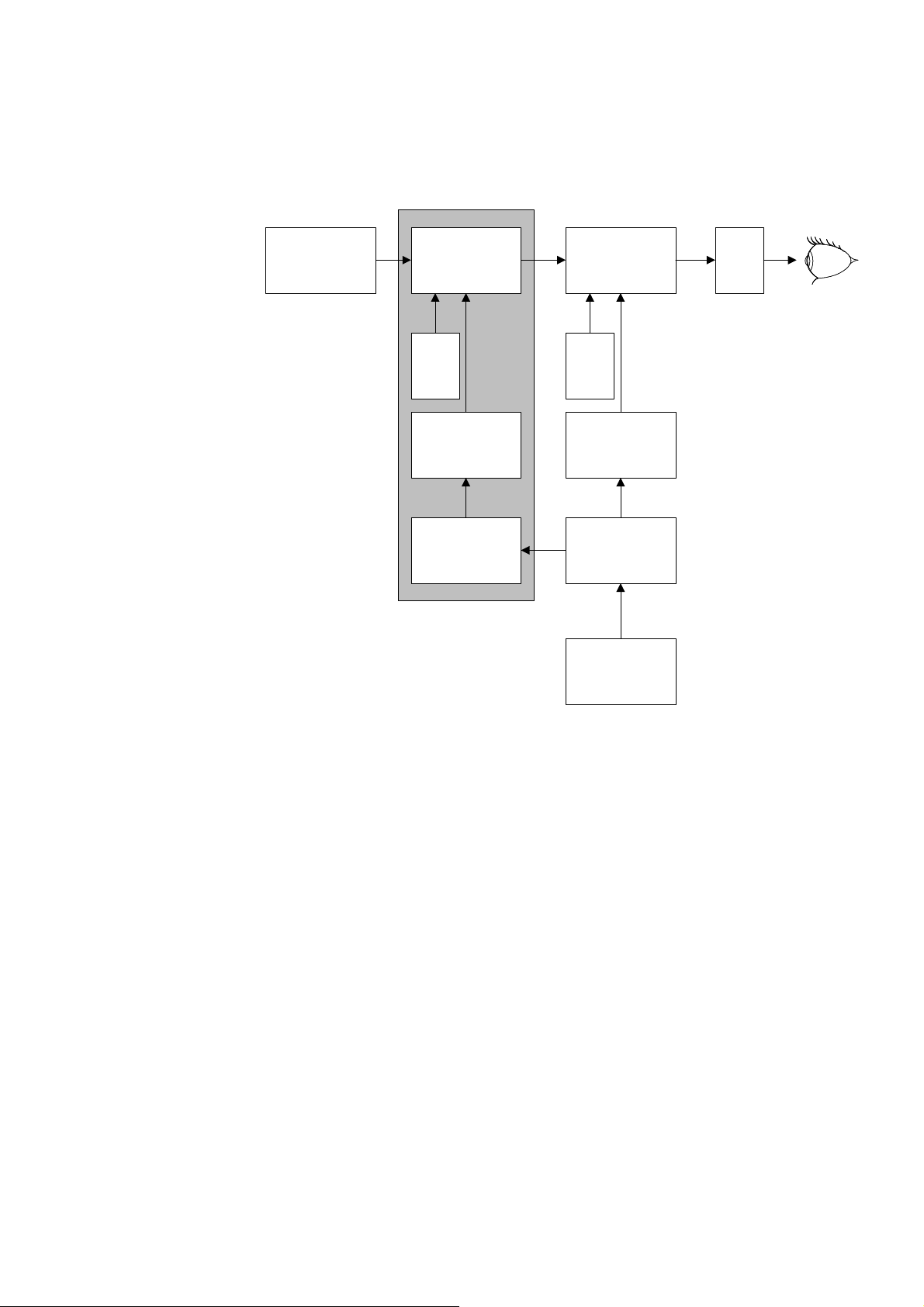
Theory of operation
3.2.2 Optical path block diagram
The optical path includes the viewing, aiming beam and treatment beam paths. The aiming and
treatment paths originate in, and exit from, the delivery head.
Binocular,
magnification
changer and eye
safety filter
SLT folding
mirror
635 nm
SLT
DAM
SLT attenuator
(includes energy
monitor, pulse
detector and shutter)
532 nm
KTP crystal
SLT Delivery Carriage
635 nm
1064 nm
YAG folding
mirror
YAG
DAM
Beam expanding
telescope (posterior
offset)
1064 nm
YAG attenuator
(includes energy
monitor, pulse
detector and shutter)
1064 nm
YAG laser
(including trigger)
Objective
lens
sm_tsu_0007
3.2.3 Overview
The Tango, Solo and Ultra Q include a:
slit lamp
delivery head
console.
A remote control is used to control the device (refer to the user documentation for more
information).
Refer to 7.4 Module identification on page 86 for exploded views of these devices.
3.2.4 Slit lamp
Viewing path
The viewing path consists of a binocular assembly (delivered with 12.5x eyepieces), magnification
changer, safety filter, folding mirror, and objective lens. The magnification of this standard system is
16x. Eye safety filters in the viewing path between the binocular and folding mirror module limit
treatment laser exposure to the operator’s eyes to a level below the Class 1 safety limit. When the
treatment laser is turned off, the device can be used as a normal diagnostic slit lamp. The
illumination system comprises a 30 W halogen lamp. The light from this lamp is delivered to the
viewing plane through various lenses and prisms.
24
8436015EN-01
3.2.5 Delivery head
The laser system consists of a number of optical modules, which are mounted on a common set of
precision machined and aligned rails mounted in the delivery head. This ensures accurate and
repeatable positioning of the modules.
Common modules (Tango, Solo and Ultra Q)
Trigger
There are two low voltage inputs to the trigger module, both +5 V DC as well as the DC voltage
from the YAG power supply (350-900 V DC). When one low voltage input is momentarily switch to
ground, it drives the pulse transformer which converts the DC input (350-900 V DC) into a high
voltage (12 kV) pulse.
This high voltage pulse is delivered to the flash lamp anode and cathode connections via the thick
wires connecting the trigger to the cavity.
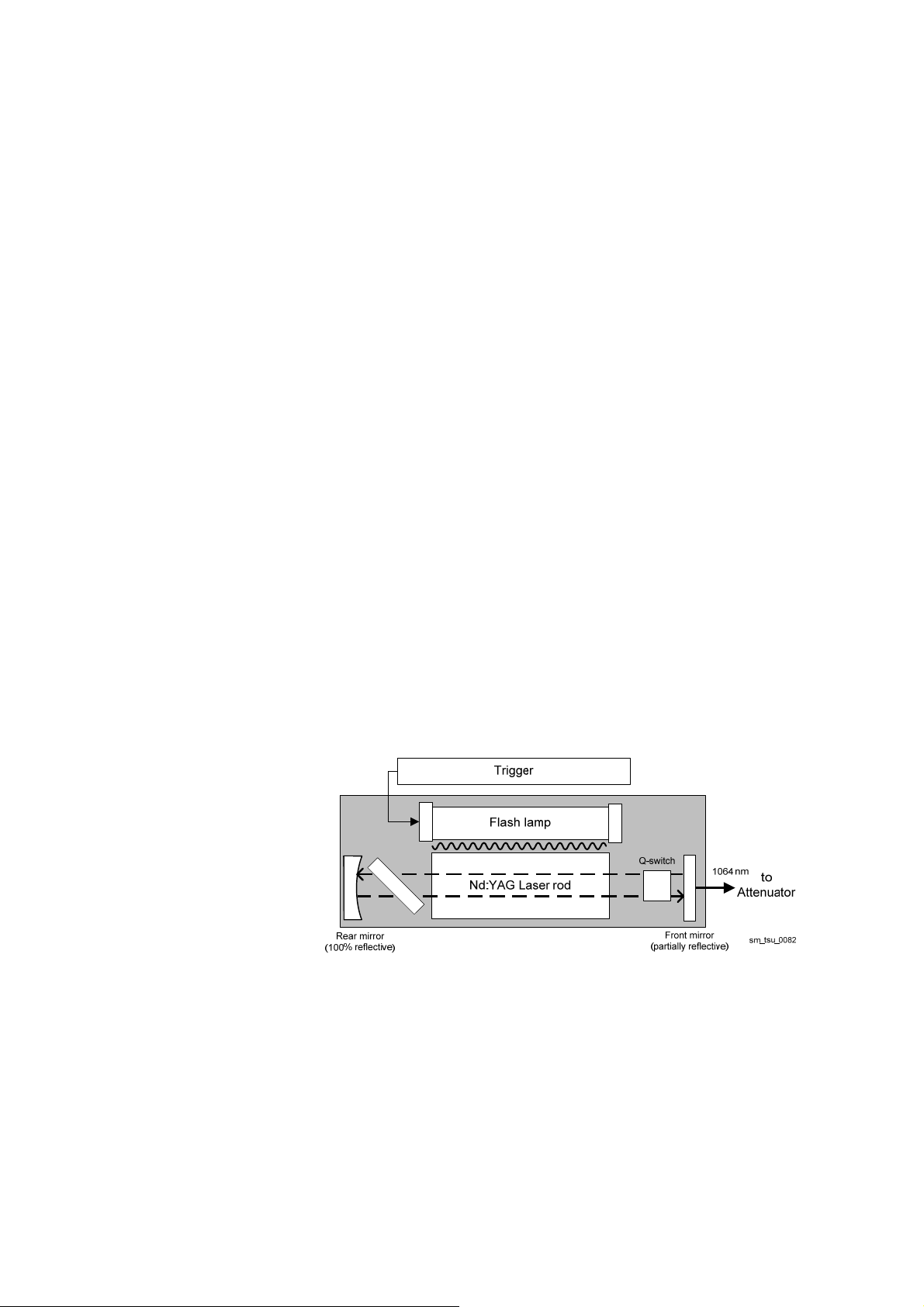
YAG laser cavity
The YAG laser body contains a flash lamp, to optically pump a solid-state crystal material made of
neodymium, yttrium, aluminium and garnet (Nd:YAG).
When the fire switch is pressed, the microprocessor sends a signal to the trigger module. This
signal energises a pulse transformer inside the trigger module, which produces a 12 kV trigger
pulse to the trigger connection of the flash lamp. This trigger pulse ionises gas inside the flash
lamp, which causes the gas to electrically conduct (ionise). This ionised gas discharges the high
voltage from the cathode to the anode, and the energy is released as a bright flash of light from the
flash lamp.
Various portions of the emitted wavelength spectrum are absorbed by the laser rod, which reemits the light. The re-emitted light bounces back and forth between the laser mirrors, building up
in energy until the Q-switch opens, releasing a pulsed laser light.
The Tango and Solo SLT treatment beams are formed by frequency doubling the 1064 nm
wavelength using a KTP crystal in the SLT carriage, producing a 532 nm laser beam.
Tango, Solo and Ultra Q Service Manual
8436015E
P
o
l
a
r
i
s
er
N-01 25

Theory of operation
Fire control board
The fire control board is mounted in the delivery head and:
controls the shutter motor and monitors the shutter sensors
triggers the flash lamp
controls the energy delivered via each optical pathway
controls the diode aiming beam intensity of each optical pathway
measures the energy of the treatment beam (energy detector is mounted on the attenuator)
measures the number of pulses delivered each shot (pulse detector is mounted on the
attenuator)
stores all the calibration information and system specific parameters
monitors external interlocks
selects joystick or footswitch activated delivery of the treatment beam
allows entry into Engineering mode.
The fire control board communicates with the rest of the system via an RS485 communication
bus.
YAG specific modules (Tango and Ultra Q)
Beam expanding telescope (BET)
The YAG beam expanding telescope is an optical module that comprises positive and negative
lenses, and an optic wedge. It accepts the 3 mm diameter laser beam from the YAG cavity and
expands it to approximately 27 mm in diameter.
Due to the inverse relationship between diameter of the beam entering the objective lens and
focused spot size, the laser beam is expanded to the largest possible size in order to decrease the
focused spot size and increase the performance of the instrument.
This module incorporates a starwheel adjusting mechanism that allows the laser focus to be
adjusted with respect to the aiming beam and viewing focal planes.
The BET module provides an offset control that is adjusted using the posterior offset control. The
posterior defocus can be accurately set by changing the optical separation of the positive and
negative lens sets in the beam expanding telescope. It allows repeatable positioning of the focuses
at the three indent positions.
YAG folding mirror
The YAG folding mirror module is not adjustable, and is the largest optic in the device. It bends
both the YAG laser and aiming beams through 90 degrees, to be coaxial with the operator’s
viewing axis and to exit the system through the objective lens.
The module consists of a laser folding mirror, and aiming beam alignment mirrors.
The laser folding mirror is highly reflective at the YAG laser wavelength, yet transmits the visible
aiming laser wavelengths. The SLT treatment beam also passes through the YAG folding mirror
without reflection.
The aiming beam alignment mirrors are the two smaller mirrors in the module. The mirror closest to
the diode aiming module reflects approximately 50% of the incident light, and the remainder is
totally reflected from the second mirror. Both these mirrors are mounted at 45 degrees on
adjustable arms, which allows the position of each arm to be set separately with respect to the
YAG laser beam.
26
8436015EN-01
Tango, Solo and Ultra Q Service Manual
Diode aiming module (DAM)
The separate YAG diode aiming module consists of a diode laser, beam monitor, collimator lens
and associated circuitry. The laser diode is powered by +8 V from the board on the attenuator
module.
The diode emits a 635 nm red laser beam, which is expanded to increase the diameter to 7 mm.
The final focus of the aiming beams is accomplished by adjusting the position of the laser relative
to the top lens of the YAG BET.
Circuitry on the attenuator board regulates the current to the laser diode, monitors the output of
the laser diode to control its output.
The output intensity is controlled by the fire control board, which reads the value of the aiming
beam intensity control potentiometer positioned on the slit lamp base, and pulse width modulates
the output of the laser from approximately 10% to 100%, according to the control position.
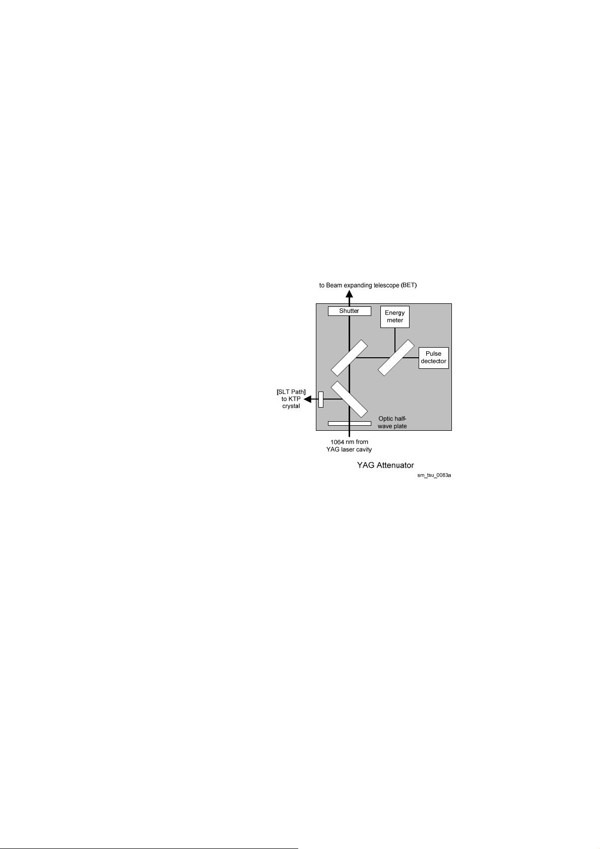
Attenuator, shutter and energy monitor
tter
i
Beam spl
Po
l
a
r
i
s
e
Beam splitter
r
The attenuator is an optical assembly that controls the laser energy output delivered to the
treatment site. The YAG laser cavity output is fixed, and the energy is optically ‘attenuated’ to
control the amount delivered via the attenuator module.
The laser cavity output passes through a half-wave plate that rotates the polarisation of the beam.
The half-wave plate position is determined by the predicted (set) energy control.
A beam splitter samples 11% of the laser output and directs this to the energy monitor and pulse
detector (which samples for under or over-pulses).
The beam then enters a shutter absorber. When the shutter is closed, a total beam block absorbs
the incident energy. When the shutter is open, which can only occur when READY is selected, the
beam passes through to a beam expanding telescope.
The Tango attenuator includes a beam switch to direct output to the SLT optical path.
8436015E
N-01 27
Theory of operation
SLT specific modules (Tango and Solo)
SLT DAM
This is similar to the YAG DAM. The beam is expanded to a diameter of 3 mm.
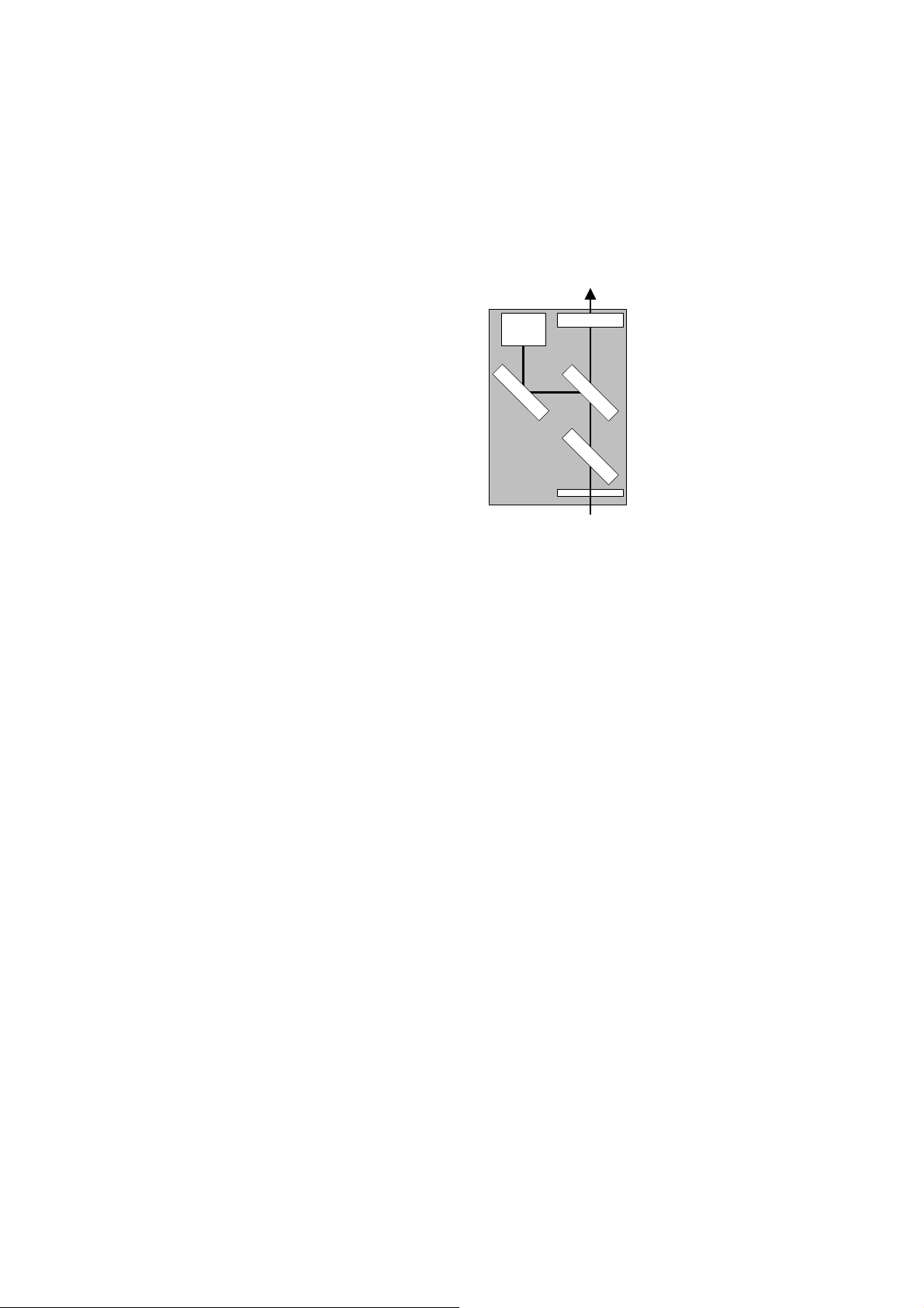
SLT Attenuator
to SLT folding mirror
ter
Shutter
B
e
am splitter
Polariser
532 nm from
KTP crystal
sm_tsu_0083b
Energy
meter
Beam spli
t
Optic half-
wave plate
SLT Attenuator
This is similar to the YAG attenuator. There is no beam switch and the treatment beam output is
reflected by the SLT folding mirror (to the YAG folding mirror).
Frequency doubler (KTP crystal)
The KTP crystal (potassium titanyl phosphate) produces 532 nm pulses from the 1064 nm YAG
pulse.
SLT folding mirror
The SLT folding mirror reflects the SLT treatment beam and aiming beam through 90 degrees. This
means that they are coaxial with the operator’s viewing axis and can exit the system through the
YAG folding mirror module and objective lens.
3.2.6 Console
YAG power supply
The YAG power supply converts a 15 V DC input into a high voltage that is used to charge storage
capacitors. The energy from the storage capacitor is supplied to the flash lamp, which is controlled
by the trigger module.
The laser operates on single, double and triple pulse modes, which are determined by the voltage
levels output from the storage capacitor. The capacitor voltage is determined by the voltage level
set by the microprocessor via the RS-485 communication bus.
When the system is turned on, power is applied via the ‘+15 V INPUT’ to the ‘Power on/off’
section of the supply. The ‘LASER ON/OFF’ line is controlled by the YAG PSU microprocessor.
When the YAG PSU control circuit is powered up and determines that no faults exist, the ‘LASER
ON/OFF’ line activates the relay K1 charging up capacitors C13 and C27 (the main storage
capacitors in the OUTPUT STAGE).
28
8436015EN-01

If the YAG PSU control circuit detects a fault, the ‘LASER ON/OFF’ line goes high, shutting the
YAG power supply down, and the ‘RESET I/P’ line goes high. This causes the storage capacitors
C13 and C27 to be discharged through the dump/reset circuit.
When the fire switch is pressed, the complex programmable logic device (CPLD) on the fire control
board sends a signal to the trigger module, and the YAG laser is triggered to fire. This causes the
main storage capacitor (C13 and C27) to discharge across the flash lamp and to immediately
charge up again. The ‘FIRE DETECT’ section of the power supply detects when the capacitor is
charged. When the storage capacitors are charged to the correct voltage, the ‘YAG PSU READY’
line goes low, indicating that the YAG power supply is ready to be fired again.
DC power supply
The DC PSU is a medical grade switch-mode power supply that converts AC mains to the low DC
voltages to operate the rest of the system.
The switched mode power supply module provides 15 V DC to the system. This module accepts a
mains input voltage in the range of 90 to 264 V AC.
3.2.7 Start up sequence
Tango, Solo and Ultra Q Service Manual
When the key is turned to On and the Laser On/Off switch is pressed (On), the following self tests
and initialisations occur:
1 The LCD is turned on and displays a welcome message and system version number for
two seconds.
2 The system is set to single pulse mode (YAG treatment laser in Tango and Ultra Q, or
SLT in Solo) and displays the current energy setting.
3 The microprocessor checks that the shutter is closed.
If the shutter is open, the microprocessor shuts down the treatment laser system and
displays an error. If the shutter is closed, the microprocessor checks that the Nd:YAG
storage capacitor is charged.
4 As soon as the capacitor is fully charged, the power supply sends a ‘charging
complete’ signal to the microprocessor.
5 The microprocessor sends signals ordering a series of test shots to be fired.
The shutter is closed during test firing.
6 The sampled energy from the last test fire is displayed on the LCD.
7 The microprocessor checks for fault conditions.
If a fault condition is detected, the system shuts down, and an error code is displayed.
8 The microprocessor checks the aiming laser detector signal to ensure the aiming laser
is operational.
8436015E
During operation, the microprocessor continually monitors:
the four remote control buttons
treatment energy selection
aiming laser detector signal
pulse selection
fire switch operation.
N-01 29

Theory of operation
If the operator changes any of these controls, the microprocessor detects the change and
responds accordingly.
The aiming laser detector signal is a status signal, which is not controlled by the operator. It is a
safety feature to ensure the treatment laser cannot be fired if the aiming laser is not operational.
3.2.8 Firing sequence
After the start up sequence is completed and all conditions are met, READY status must be
selected to enable firing. The laser is fired by pressing the fire switch on the joystick or pressing the
footswitch (if attached).
Whenever an attempt is made to fire, the following processes occur:
1 The microprocessor reads READY status is selected.
2 The microprocessor reads the fire instruction.
3 The microprocessor sends a fire signal to the trigger module.
4 The shutter motor opens the shutter.
5 Two sensors inside the SLT or YAG attenuator module (as selected) detect the shutter
position. If the shutter malfunctions, the microprocessor shuts down the power supply,
disables the unit and displays an error.
6 The trigger pulse is generated once the safety shutter is detected to be in the open
position.
7 The flash lamp converts the energy in the storage capacitor into a flash of light.
8 This flash in turn energises the laser rod.
9 The Nd:YAG cavity outputs a pulse (or pulses).
10 The shutter motor closes the shutter.
30 8436015EN-01
 Loading...