

Page 1

Sideboard
ASSEMBLY INSTRUCTIONS
Page 2

Guidelines
Thank you for selecting an Elle Decor Collection piece!
FAILURE TO FOLLOW THESE WARNINGS
WHEN IN USE COULD RESULT IN INJURY
Our primary objective is to provide fast, friendly
customer service to all of our customers. We are here
to help if you have any questions, comments, or are
in need of warranty replacement parts.
Please call us toll free at:
U.S. Monday - Friday 6:00am - 5:00pm PST,
U.K. Monday - Friday 2:00pm - 1:00am U.K. Time
Or visit our website:
www.truecustomersupport.com
www.trueinnovations.com
1-855-372-2315 U.S.
0-800-051-6775 U.K.
• Do not stand on the item or use as a step ladder
• Do not use this item unless all bolts and screws are
firmly secured and fastened.
• Check all bolts and screws every 90 days. As necessary
tighten if any are loose.
• Lift up then move. Pushing over or dragging this
product can result in an injury or cause damage to the
floor and piece.
2
Page 3

Pre-Assembly Preparation:
Please read through this instruction booklet before
beginning assembly of this item.
Two adults are recommended for assembly.
• Clear out the space for assembly and lay out all
parts on Parts List, extra room will allow you to
easily determine if all the pieces are present.
• Save all packing materials until assembly is
complete to avoid accidentally discarding smaller
parts or hardware.
• Keep small parts and pieces away from children
and pets until fully assembled.
• Please check for any loose screws and tighten them
before you use.
WARNING: DO NOT LET
CHILDREN PLAY IN OR
AROUND THE UNIT DUE
TO THE POSSIBLE RISK
OF INJURY.
3
Page 4
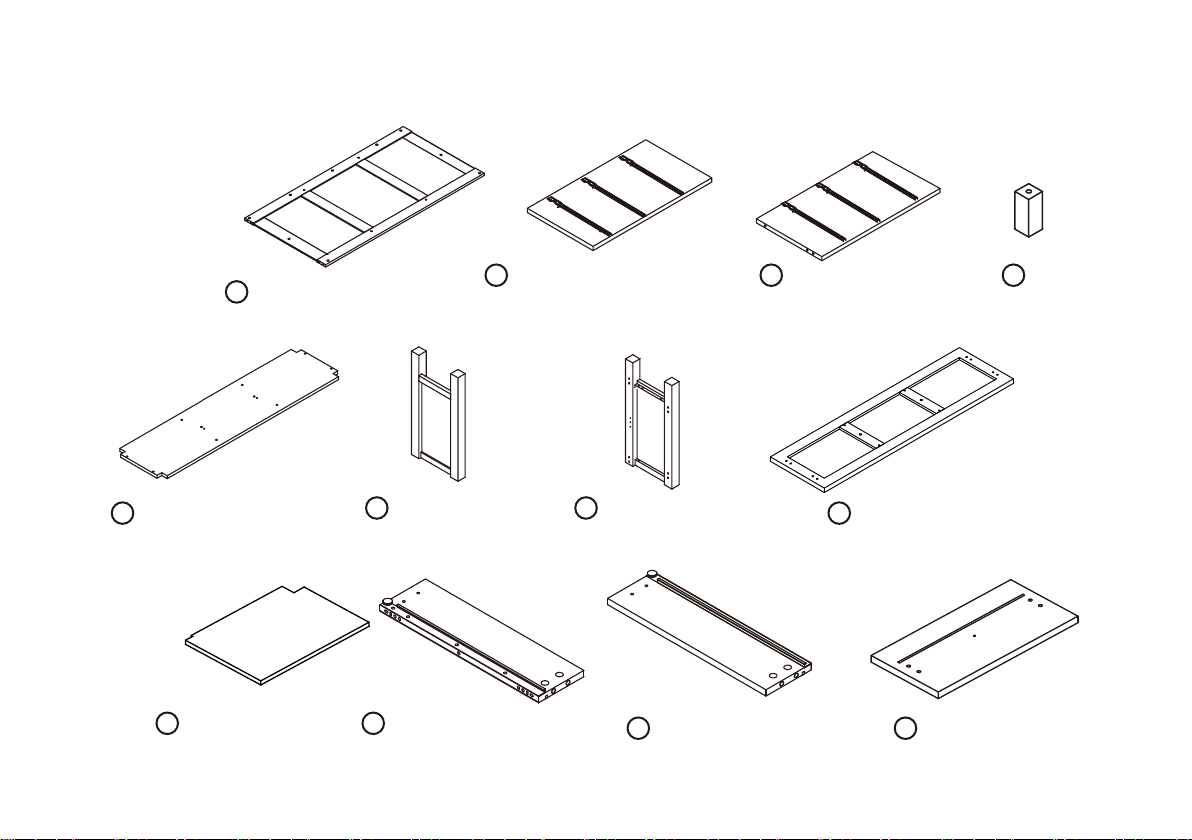
Parts List
E
Bottom Panel X 1
Back panel X 1
A
B
Central Panels X 1 Central Panels X 1
F
Side panel X 1 Side panel X 1
G
Feet X 2
C
Top Panel X 1
H
D
I
Shelves X 2
J
Drawer Side Panels X 3 Drawer Side Panels X 3
K
Drawer front Panels x 3
L
4
Page 5
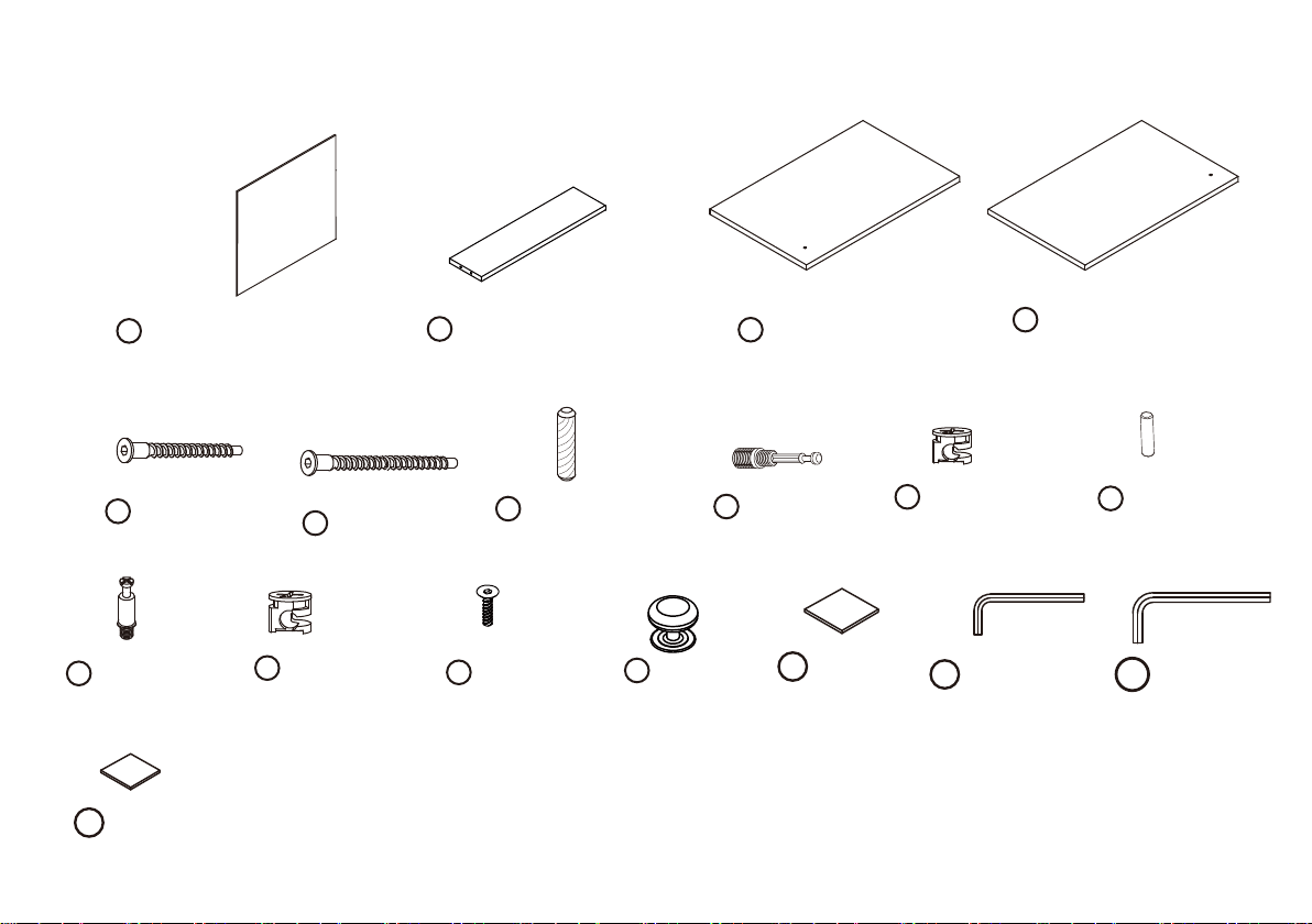
Parts List
Drawer Bottom Panels X 3
M
N
Drawer back panels X 3
Door X 1
O
P
Door X 1
Screws X 14
Q
M5 x30 MM
Cambolts X 12
W
25 MM
Pads X2
AD
30x30MM
Screws X 14
R
M7 x 50 MM
Camlocks X 10
X
10 MM
S
Bolts X 5
Y
M4 x 23 MM
Wood Dowels x 12
M8 x 30MM
Z
Knobs X 5
Camlocks X 10
T
35MM
Pads X 4
AA
40x40MM
U
Camlocks X 10
14 MM
AB Allen Key X1
M3
Shelf holder X 8
V
5 x 25 MM
M4
AC Allen Key X1
5
Page 6
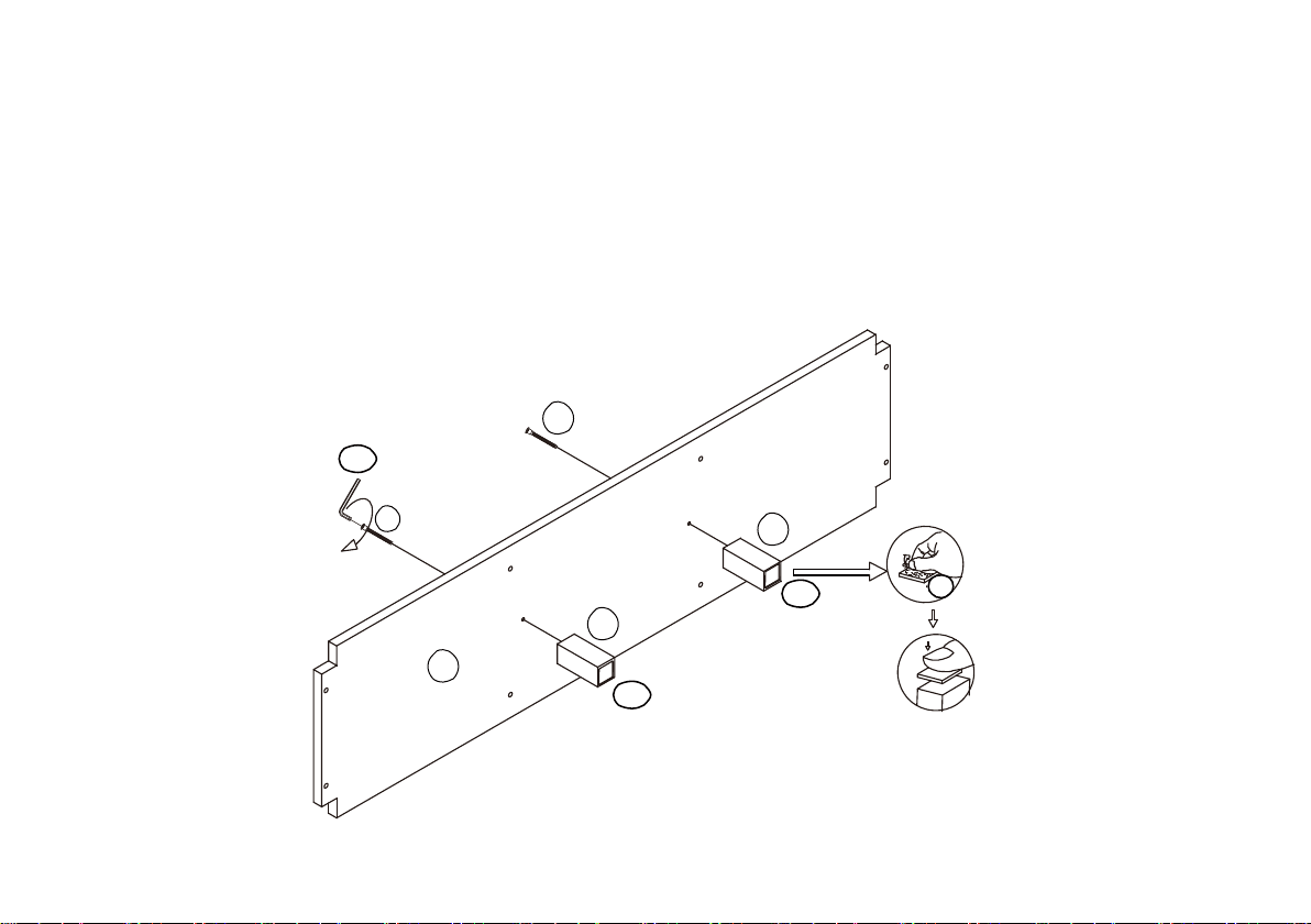
Step 1--
1. Remove all parts from the carton and place them on a protected surface or carpet.
2. Attached Feet (D) to Bottom Panel (E) with Screws (R) and tighten with Allen Key (AC).
3. Remove the cover on Pads (AD) & stick Pad (AD) on the bottom of Feet (D)
R
AC
R
D
AD
AD
D
E
AD
AD
6
Page 7
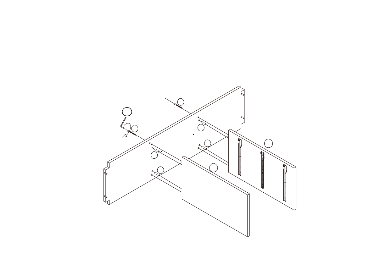
Step 2--
1. Insert Wood Dowels (S) in to Bottom Panel (E) as shown.
2. Attached Central Panel (C) & (B) as shown to Bottom Panel (E) with Screws (R) and
tighten with Allen Key (AC).
R
AC
R
S
S
S
S
C
B
7
Page 8
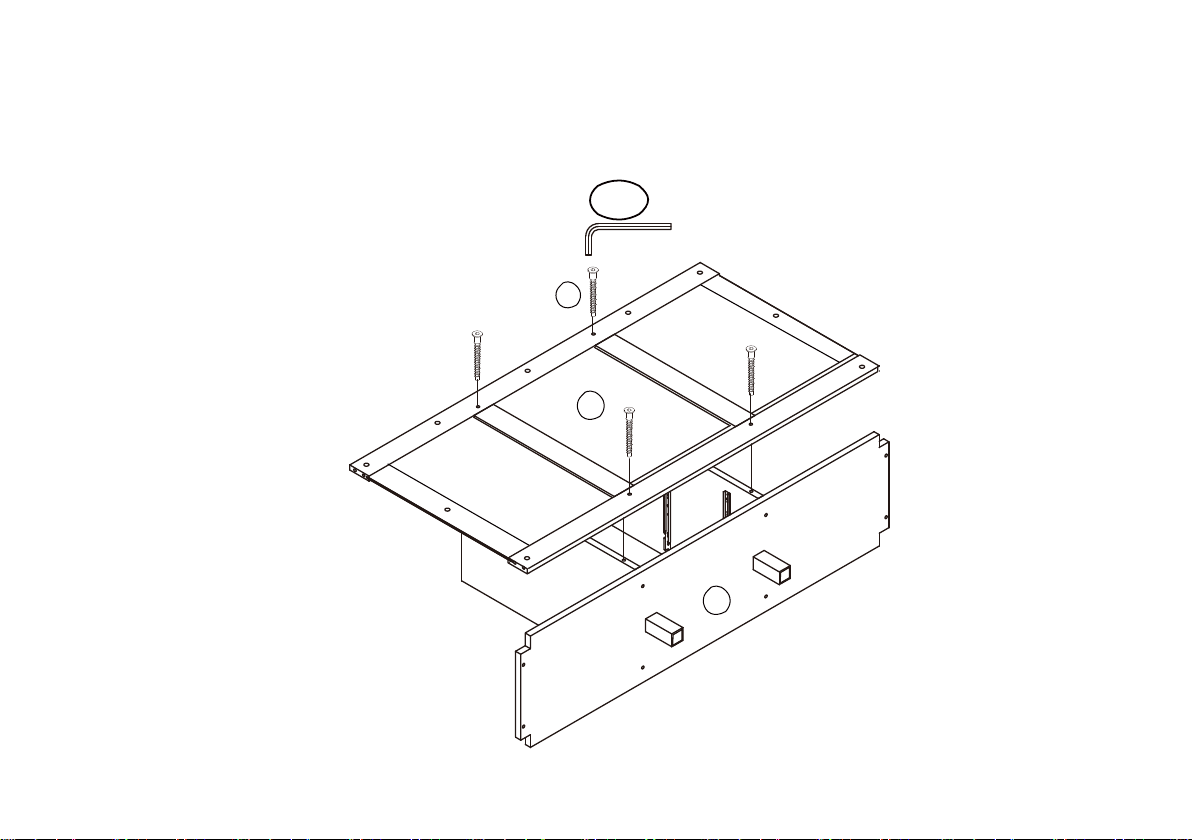
Step 3--
Attached Back Panel (A) to assembly unit as shown with Screws (R) and tighten with Allen Key (AC).
AC
R
A
E
8
Page 9
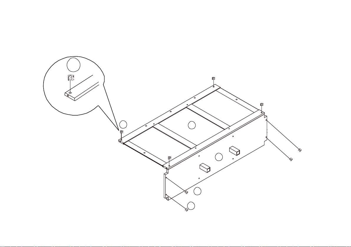
Step 4--
U
Insert the Camlocks (U) into Back Panels (A) and Bottom Panel (E) Ensuring the open
indicator is pointing towards the panel edge before tightening with a screwdriver.
U
A
E
U
U
9
Page 10
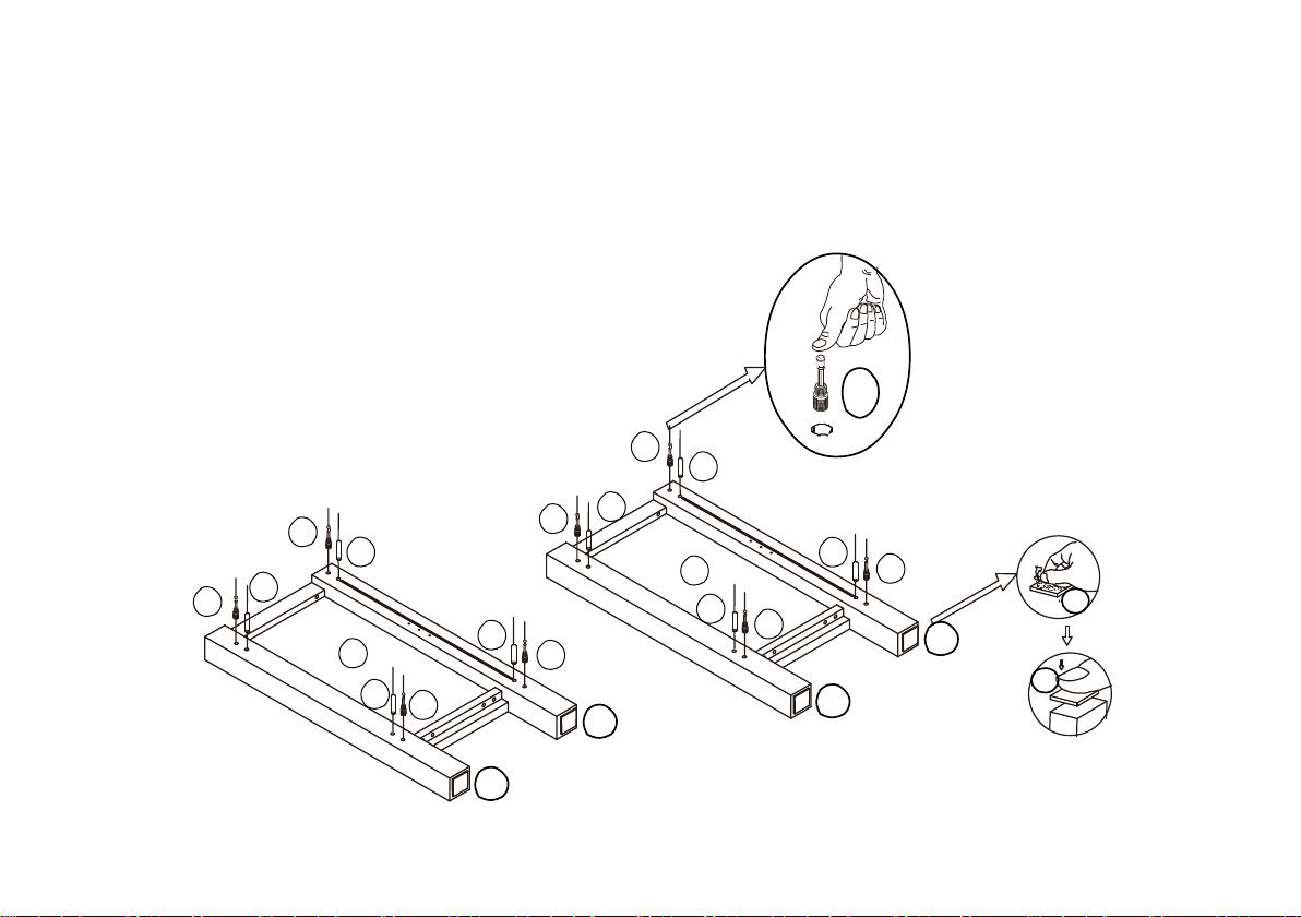
Step 5--
T
1.Insert Cambolts (T) into Side Panel (G) & (F) by hand as shown .
2.insert Wooden Dowels (S) into Side Panel (G) & (F).
3.Remove the cover on Pads (AA) & stick Pad (AA) on the bottom of Side Panel (F) & (G)
T
T
S
S
T
S
S
F
S
T
T
S
G
S
S
T
T
AA
T
AA
AA
AA
AA
10
AA
Page 11
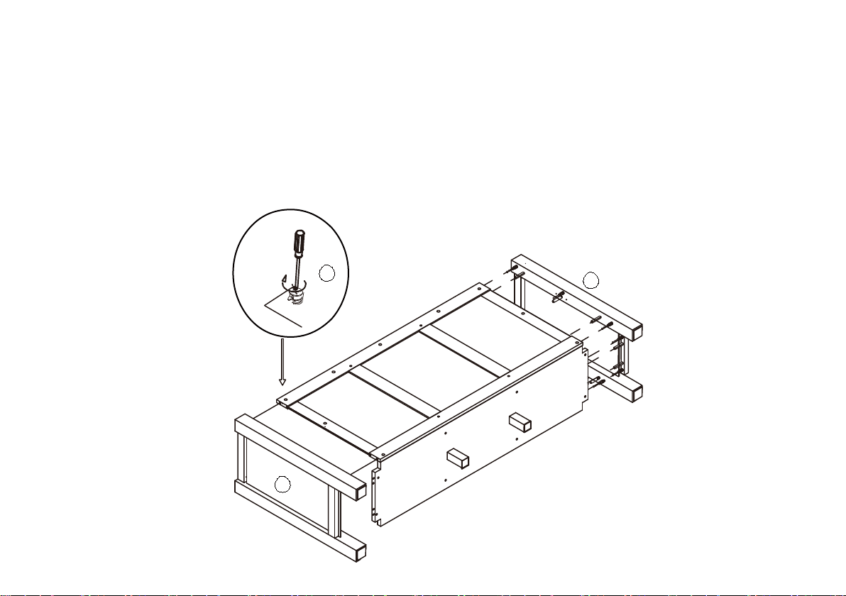
Step 6--
1.Insert the camlocks (U) into Side Panel (F) & (G).
Ensuring the open indicator is pointing towards the panel edge before tightening with a screwdriver.
2.Attach Side Panel (F) & (G) to Back Panels (A) and Bottom Panel (E)
3.Then use the screwdriver (not provided) turn clockwise to fasten the Camlocks (U)as shown
Ensuring the open indicator is pointing towards the panel edge before tightening with a screwdriver.
U
F
G
11
Page 12
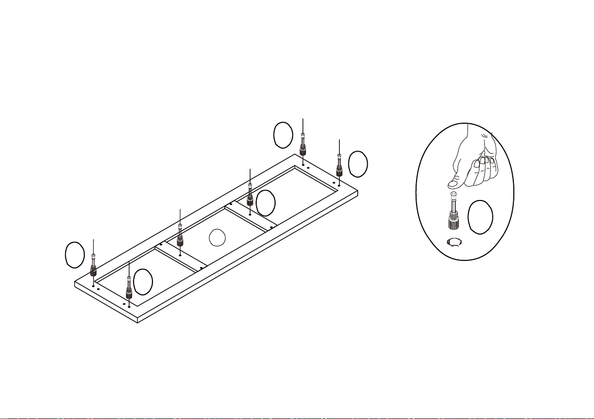
Step 7--
T
Insert Cambolts (T) into Top Panel (H) as shown
T
T
T
T
H
T
12
Page 13
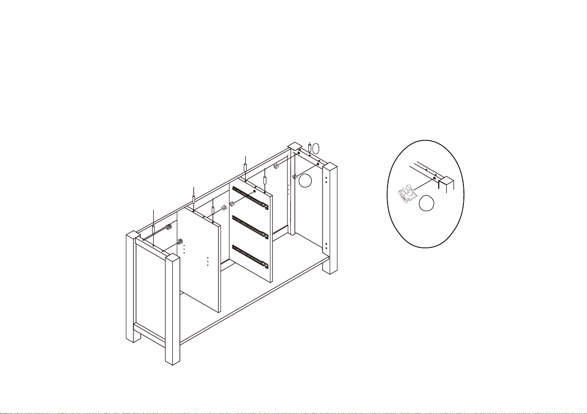
Step 8--
1.Insert the camlocks (U) into Side Panel (F), (G) & Central Panels (B), (C) .
Ensuring the open indicator is pointing towards the panel edge before tightening with a screwdriver.
2.Insert the wood dowels (S) into back panel (A), side panels (F) (G) & central panels (B) (G).
S
U
U
13
Page 14
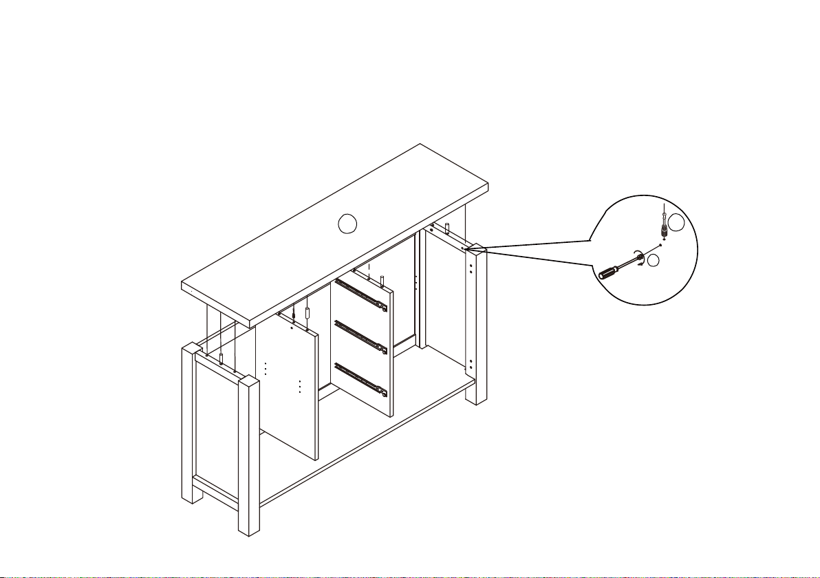
Step 9--
Attach Top Panel (H) to assembly unit Then use the screwdriver (not provided) turn clockwise to
fasten the Camlocks (U) as shown.
Ensuring the open indicator is pointing towards the panel edge before tightening with a screwdriver.
14
H
T
U
Page 15
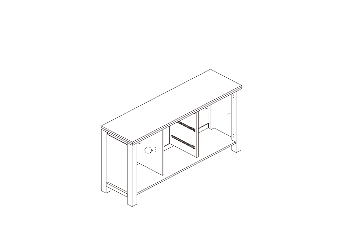
Step 10--
Insert Shelves holder (V) into Side Panel ( F), (G) and Central panel (B), (C) on correction position.
V
15
Page 16
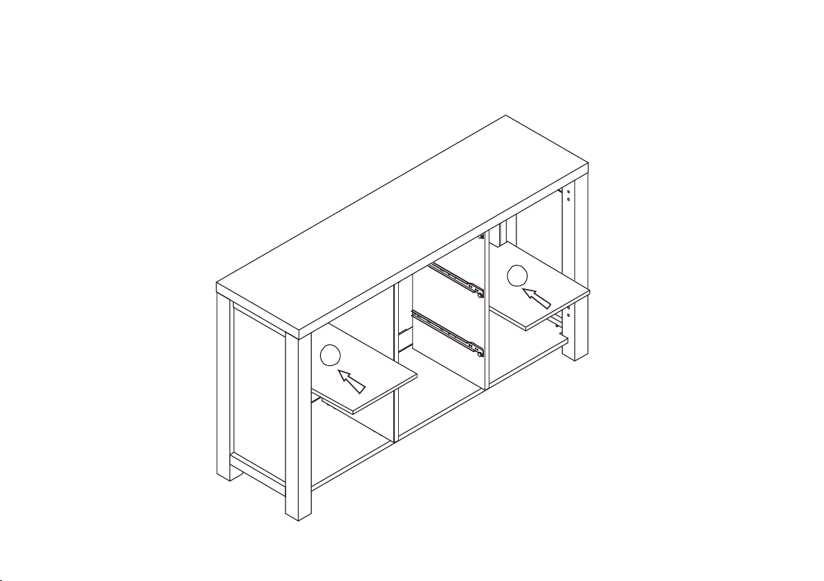
Step 11--
Insert the Shelves (I) on position.
I
I
16
Page 17
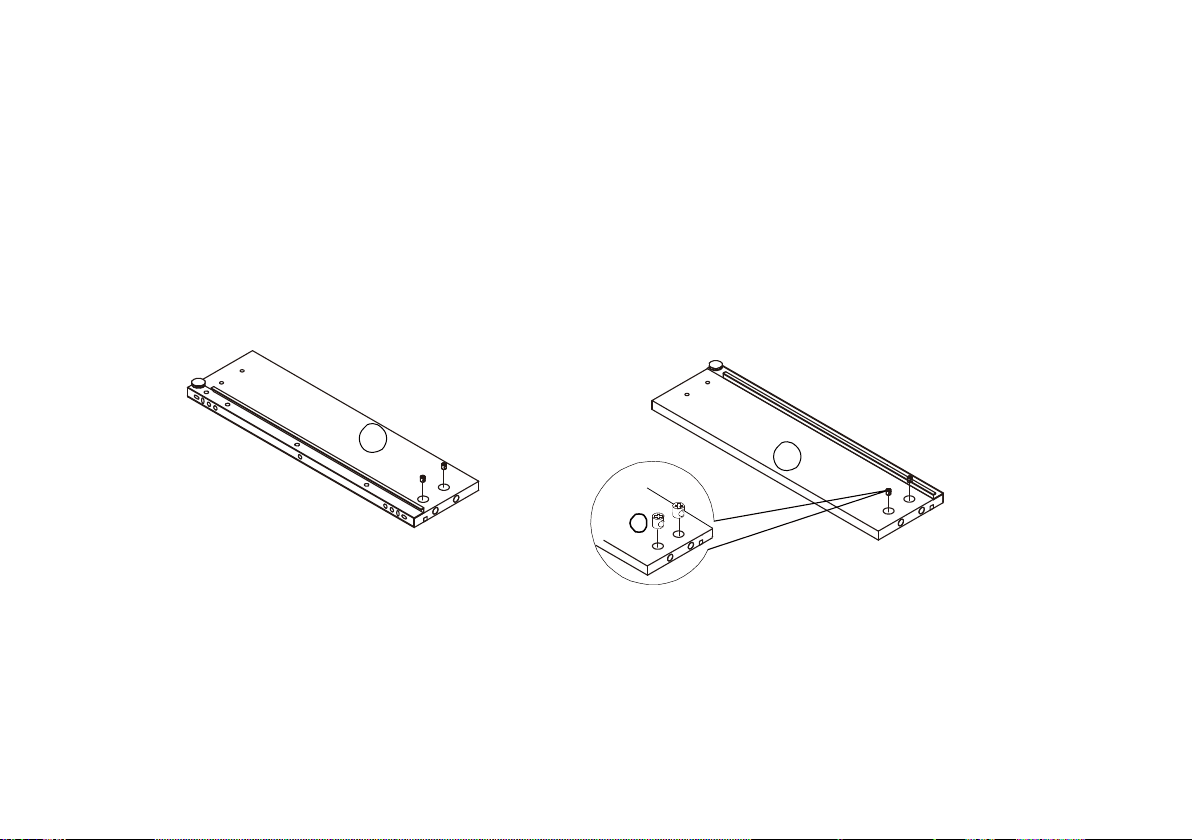
Step 12--
Insert the Camlocks (X) into Drawer Side Panels (J) & (K).
Ensuring the open indicator is pointing towards the panel edge before tightening with a screwdriver.
J
X
X3
K
X3
17
Page 18
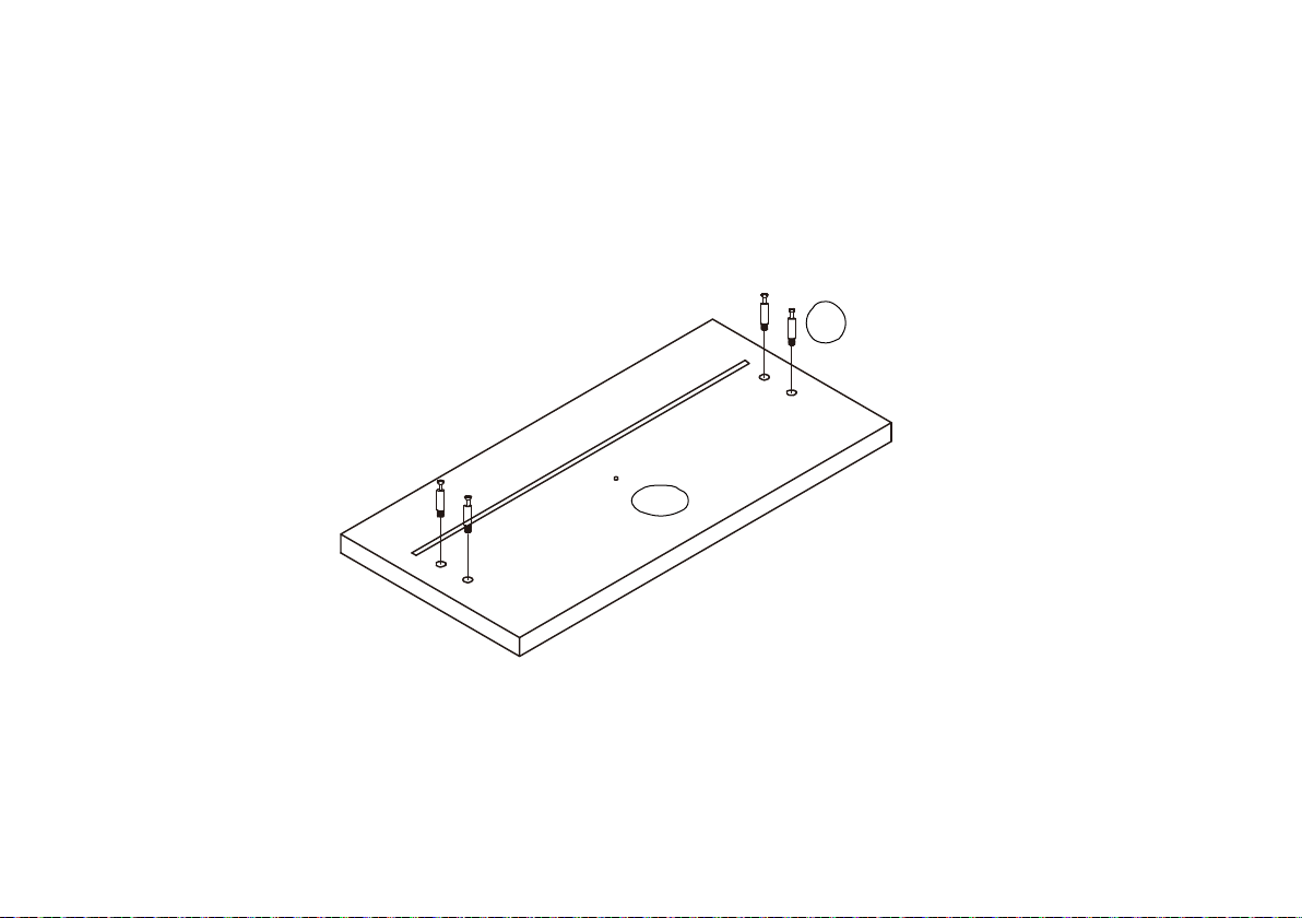
Step 13--
Insert Cambolts (W) into Drawer Front panels (L) by a screwdriver (not provided) until tight.
W
L
18
Page 19
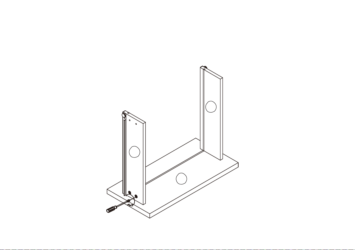
Step 14--
Attached Side Panel (J) & (K) to drawer front panels (L) as shown then use the screwdriver (not provided)
turn clockwise to fasten the Camlocks (X).
Ensuring the open indicator is pointing towards the panel edge before tightening with a screwdriver.
K
J
L
X3
19
Page 20
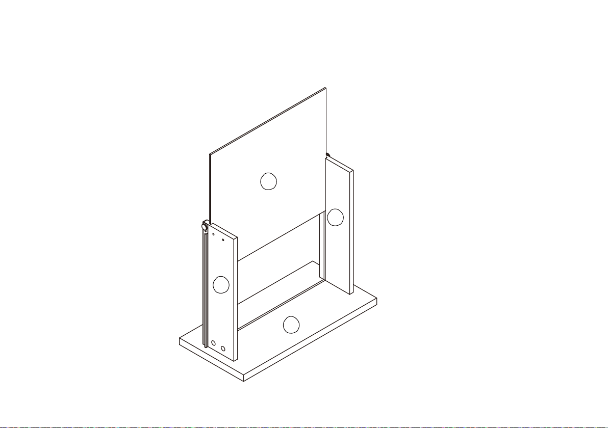
Step 15--
Slide Drawer Bottom Panels (M) into the grooves of the drawer frame.
M
K
J
L
20
X3
Page 21
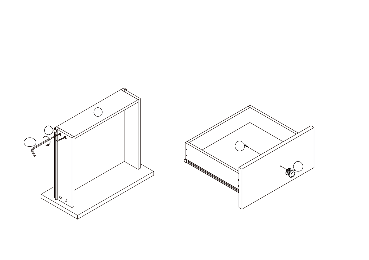
Step 16--
Q
1. Attach Drawer Back Panel (N) to assembly unit by Screws(Q) tighten with Allen Key (AB).
2. Attach Knob (Z) to Front Door Panels (L) by Bolts (Y) and tightening with a screwdriver (not
provided).
N
AB
Y
Z
X3
X3
21
Page 22
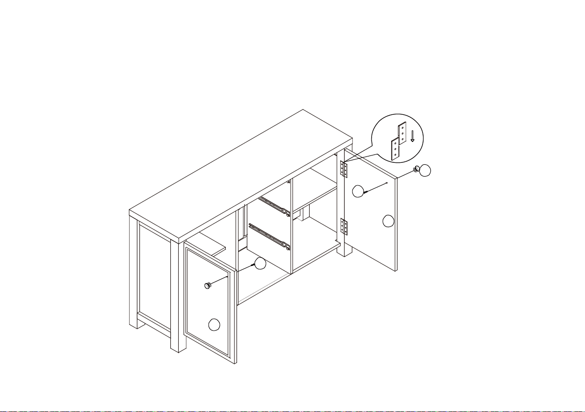
Step 17--
1. Insert the Door (P) and (O) on assembly unit as shown
2. Attached Knobs (Z) on Doors by Screws (Y) and using a screwdriver (not provided) until tight.
Z
Y
P
Y
O
22
Page 23
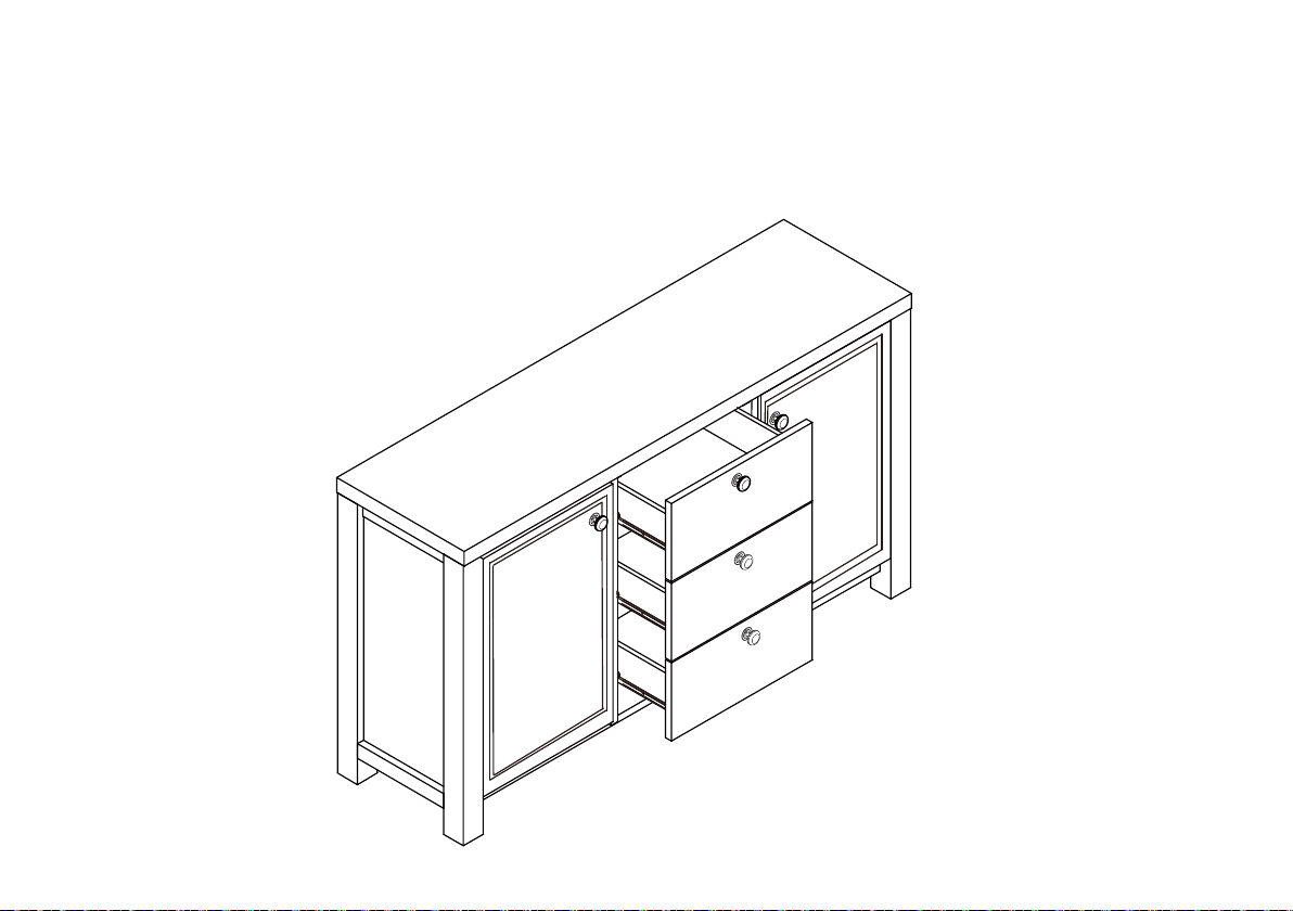
Step 18--
Insert the drawers in to assembly unit as shown.
23
Page 24
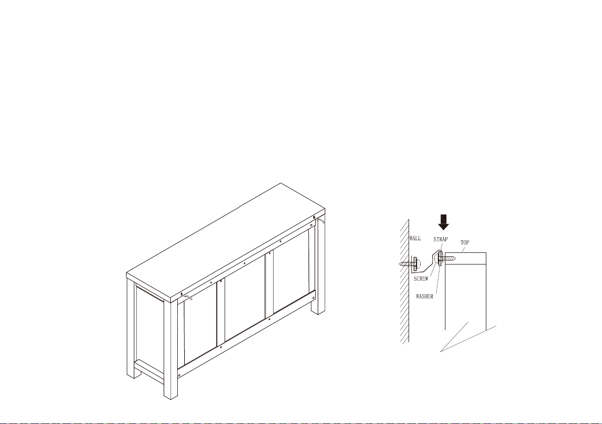
Step 19--
Warning:
Always ensure intended wall area to be drilled is free from hidden electrical wires, water
and gas pipes.
1.Secure the other end of the strap to the wall with an appropriate screw and wall plug for your
wall type (not provided).
NB: Wall fixings are not included. Please source suitable fixing for your wall type. If in doubt
please consult a local hardware store.
2.To hide the strap behind the unit, drill the hole lower than the top of unit.
24
Page 25
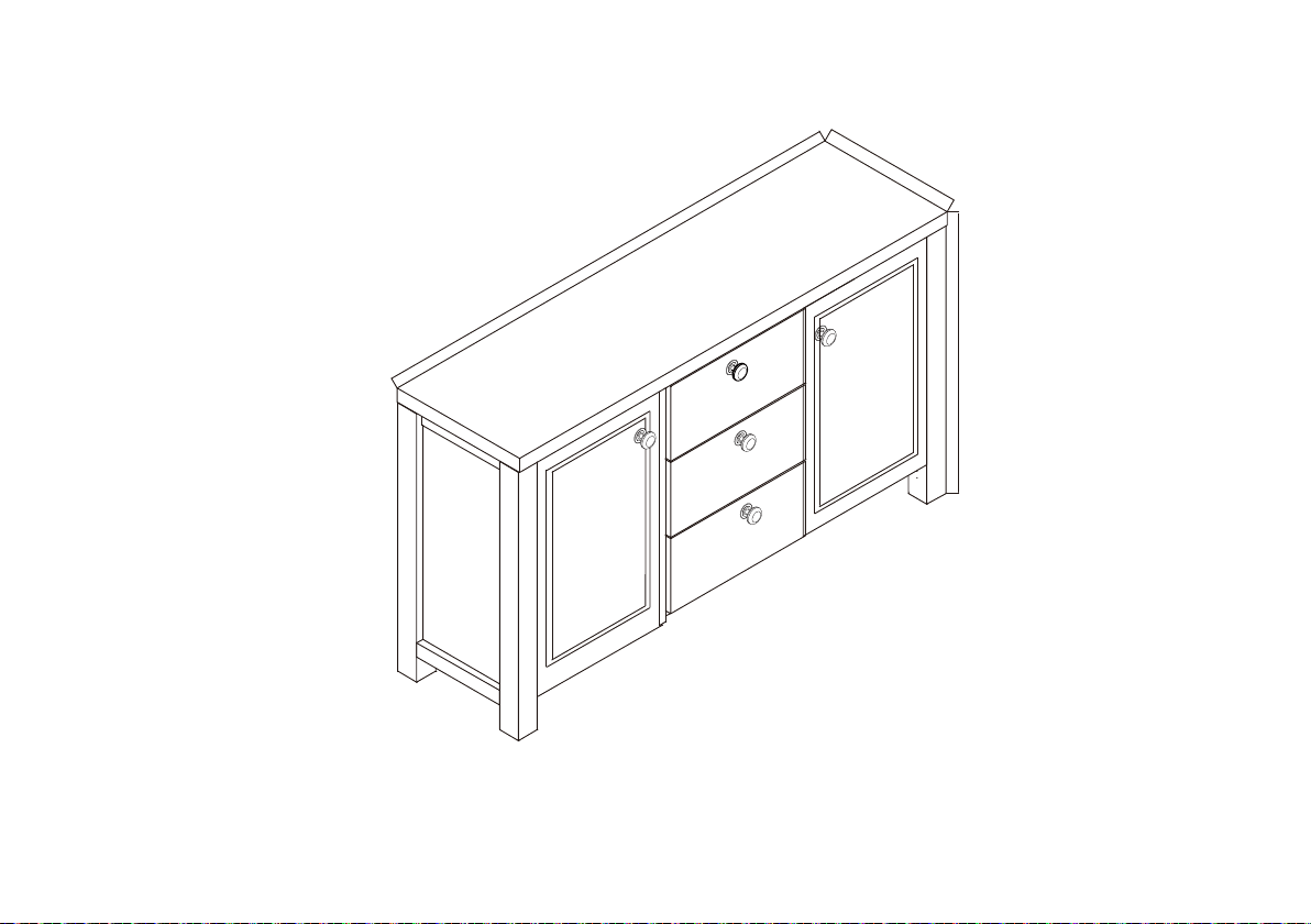
40CM/15.7"
140CM/55.1"
Product Dimension
"5.13/MC08
25
Page 26

Limited Warranty
The product you have purchased is warranted against
defects in material and workmanship while owned by
the “Original Purchaser”. The term “Original Purchaser”
is defined as that party or entity which purchases these
products from an authorized dealer or retailer as shown
by the original sales receipt. This warranty does not
apply too “as is” or previously owned products.
The manufacturer warrants its products to be free from
defects in materials and workmanship (normal wear and
tear, fading and stretching excepted), for one year from
the date of purchase, except as provided below under
the limited warranty.
This warranty gives you specific rights, and you may also
have other rights, which vary from state to state (or
country to country). All warranties are limited to the
original purchaser for normal use by a maximum of two
users. Total weight capacity per chair is 250 pounds for
a single user.
The exceptions or exclusions to this warranty are:
• Upholstery material and foam cushion material is
warranted against defects in material and workmanship
for a period of one year, beginning on the date of
purchase as shown on the original sales receipt.
• Any warranty claim that is submitted after the limited
warranty period, or without proper proof of purchase
will not include the cost of parts, labor, or delivery on
the warranted parts within a reasonable amount of time.
We reserve the right to require damaged parts to be
returned to us upon request. Natural markings such as
scars, brands, grain variations, wrinkles, color variations,
etc. will be considered normal characteristics and not
construed as defects.
• For claims or questions concerning this warr
please contact the Customer Service Department
on the web at www.truecustomersupport.com.
Be prepared to provide your name, address,
daytime phone number, the model and purchase order
number of the product, date of purchase, and the store
where it was purchased. The manufacturer requires that
the original sales receipt be submitted with all requests
to confirm that you are the original purchaser according
to our written warranty.
anty,
26
 Loading...