

Ellard Mini Standard V7 Product Instructions
Page 1 of 8
PRODUCT INSTRUCTIONS
Mini Standard V7 3phase Controller
Dallimore Rd, Wythenshawe,
Manchester. M23 9NX
T: +44 (0)161 945 4561
F: +44 (0)161 945 4566
Stock Code Description Doc No: PI-110
01003 Dalmatic Mini Standard V7 Controller
Iss: 1
Controller
Specification
Supply voltage: 3ph - 400VAC ± 10% L1,L2,L3,PE (‘N’ not required)
50/60Hz,
Mains supply protection should be provided by
either 10A/phase MCB Type ’C’ or fuse equivalent
Maximum Load Max motor load by 3 x 400VAC: 4 kW
Temperature range -10…+50°C (operating)
Humidity: Up to 93% RH non-condensing.
Auxiliary Supply 24VDC ± 20% (non-regulated)
Max load: 250mA
(without additional plug-in options)
Safety edge input: Pneumatic air switch (N/C Contact)
Electric type - 8k2 termination ± 10%
Optical type (Fraba OSE or Dalmatic TSS/RSS)
Photo sensor input Photo-sensor, 24 VDC, Relay O/P N/C
Description
The Mini-Std controller has been designed as a controller which provides the
capabilities to operate an industrial door safely under electrical control by means of
a pushbutton station or key switch
Its intended use is to be connected to a suitable motor not exceeding the load for
the controller
The unit incorporates safety features to protect people or property from damage by
automatically reversing a closing door should they be activated
This together with the auto closing function and additional facilities for plug in Loop
Detectors and radio control make this unit very versatile
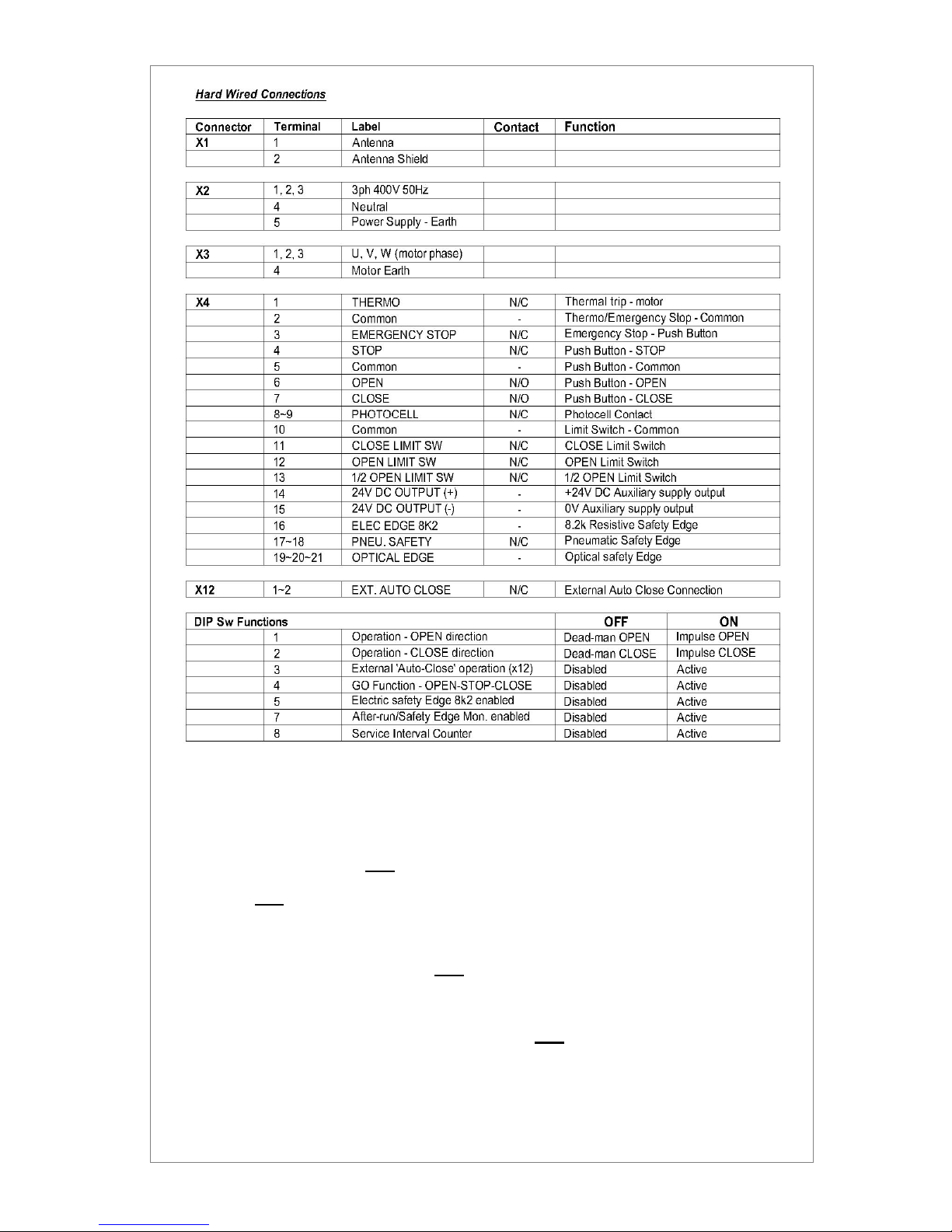
Connections are provided for Mains supply, Motor power, Travel Limits switches,
Push Buttons, Photocell and Safety Edge and 24VDC Auxiliary power (250mA max)
Page 2 of 8
The installation should only be carried out by a trained competent person and
in accordance with all local legislation. Please read the instructions in full
prior to installation
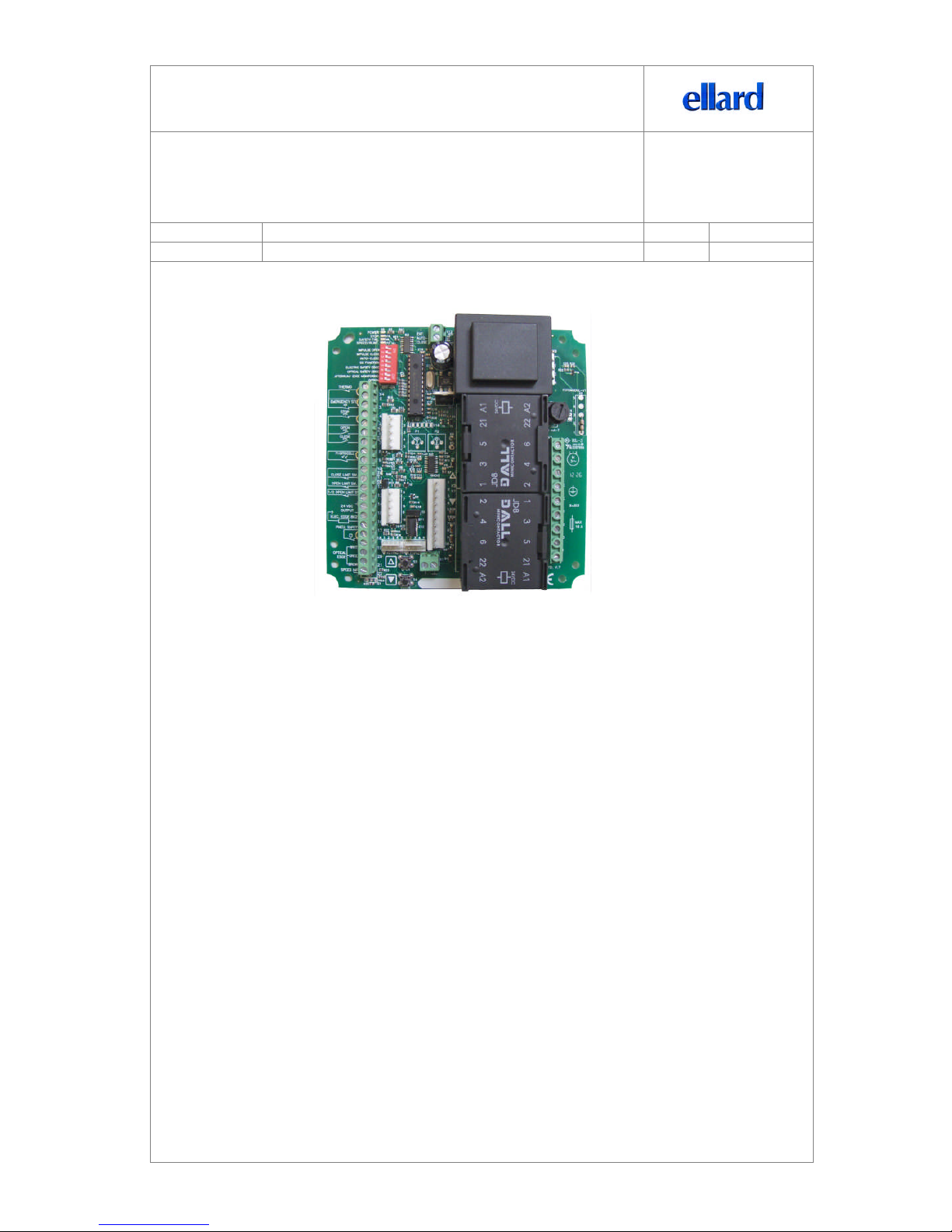
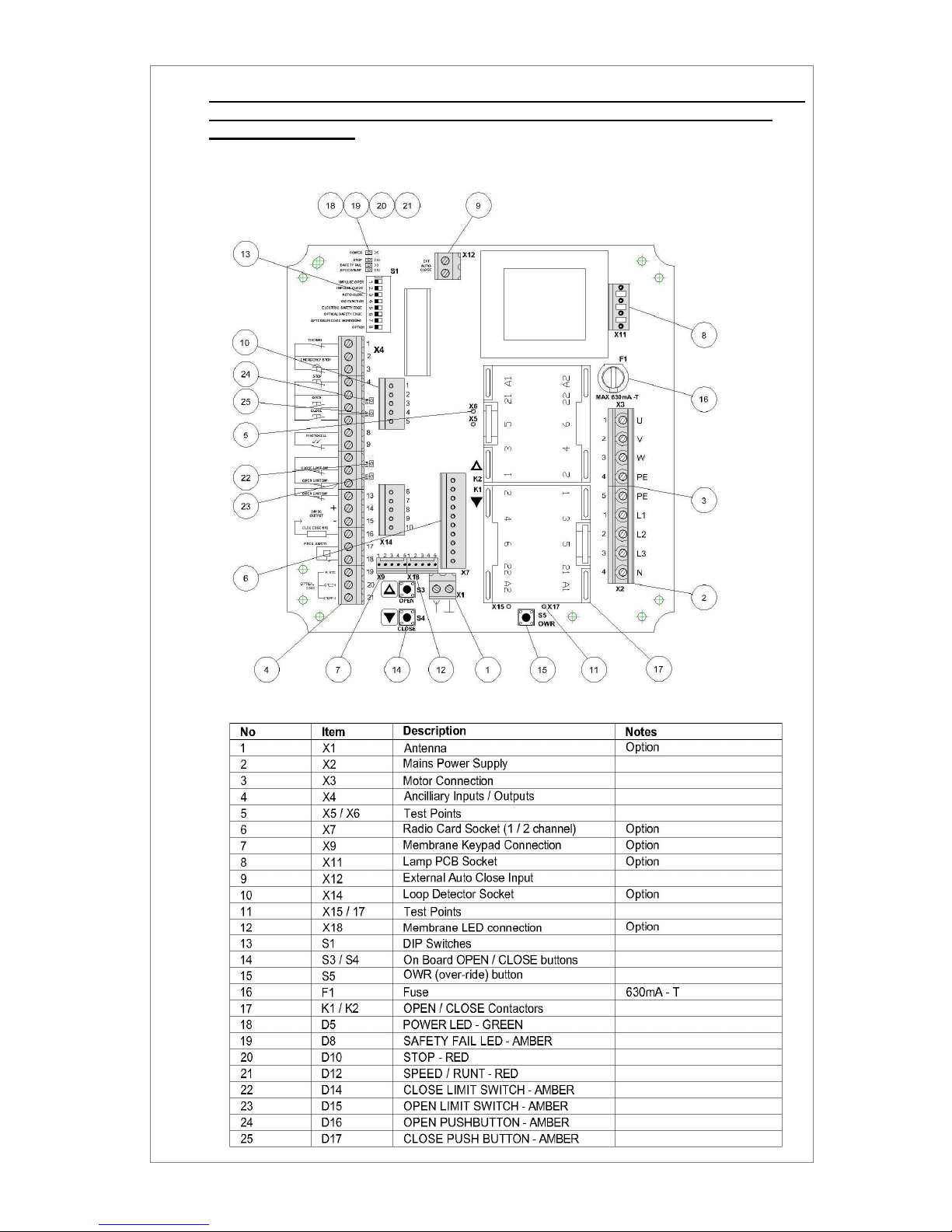
Board Layout
Page 3 of 8
Installation
1) Controller should be mounted in suitable enclosure for the environment and be:
a. Vertically mounted and free from vibration
b. Not exposed to and is free from all dust and debris
c. Fitted with appropriate cable glands to maintain IP rating of enclosure selected
d. Fitted with appropriate wall fixings used to secure the enclosure
2) Ensure that all power is OFFbefore connecting any wiring to the controller or motor referring
to the connection details in this manual,
3) Check ALL wiring connections are secure upon completion
Setting Travel Limits
1) Manually haul the door to mid position
2) Ensure ALL dipswitches are set to OFF
3) Re-apply mains supply power
4) Press the open button and observe the operating direction, the door should move in dead-
man operation in the opening direction
a. If not correct, turn the Main Supply Power OFF, rotate any two of the motor phases
U, V, W i.e. (U&V) (U&W) or (V&W)
b. Turn mains supply power ON and re-check for correct direction
5) Using pushbuttons move the door to its fully open position, then set the open travel limit cam
Repeat in the close direction setting the close travel limit cam
Fully open & close the door and check end of travel positions adjust travel limits if necessary
 Loading...