

Page 1
ellard
elec\DC2\book\20040\002
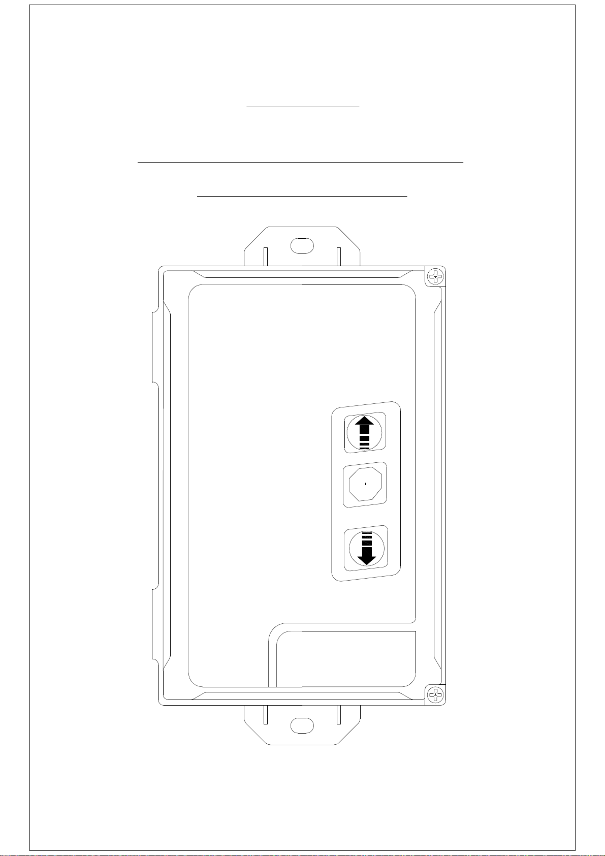
DC2 Controller
(Quick Start Guide)
STOP
Page 2
Contents
Page
General Layout
3
Mains Supply Connection
4
Tube Motor Connection
4
Volt Free Connection for 'JM' series operator or other controls
5
Volt Free Connection for 'F' 'W' and 'SD' series operator
5
Push Button Connection
6
Impulse Button Connection
6
Emergency Stop Button Connection
6
Optical Safety Edge Connection
7
8.2k Resistive Safety Edge Connection
7
Pneumatic Safety Edge Connection
7
Photocell (reflective type) Connection
7
Pre-warning Light Connection
8
Red / Green Traffic Light Connection
8
230v Courtesy Light Connection
8
Radio Receiver / Transmitter - Programming
9
Radio Receiver / Transmitter - Deleting
9
Motor Run Timer Settings
10
Closing Delay Timer Settings
10
Trouble shooting
11
Technical data11
Important Information
This booklet is a quick start guide for 'ellard' products, it is no way intended
as a direct replacement of the manufacturers manual
All safety information and regulations are contained within the
manufacturers manual should be veiwed before installation.
2
Page 3
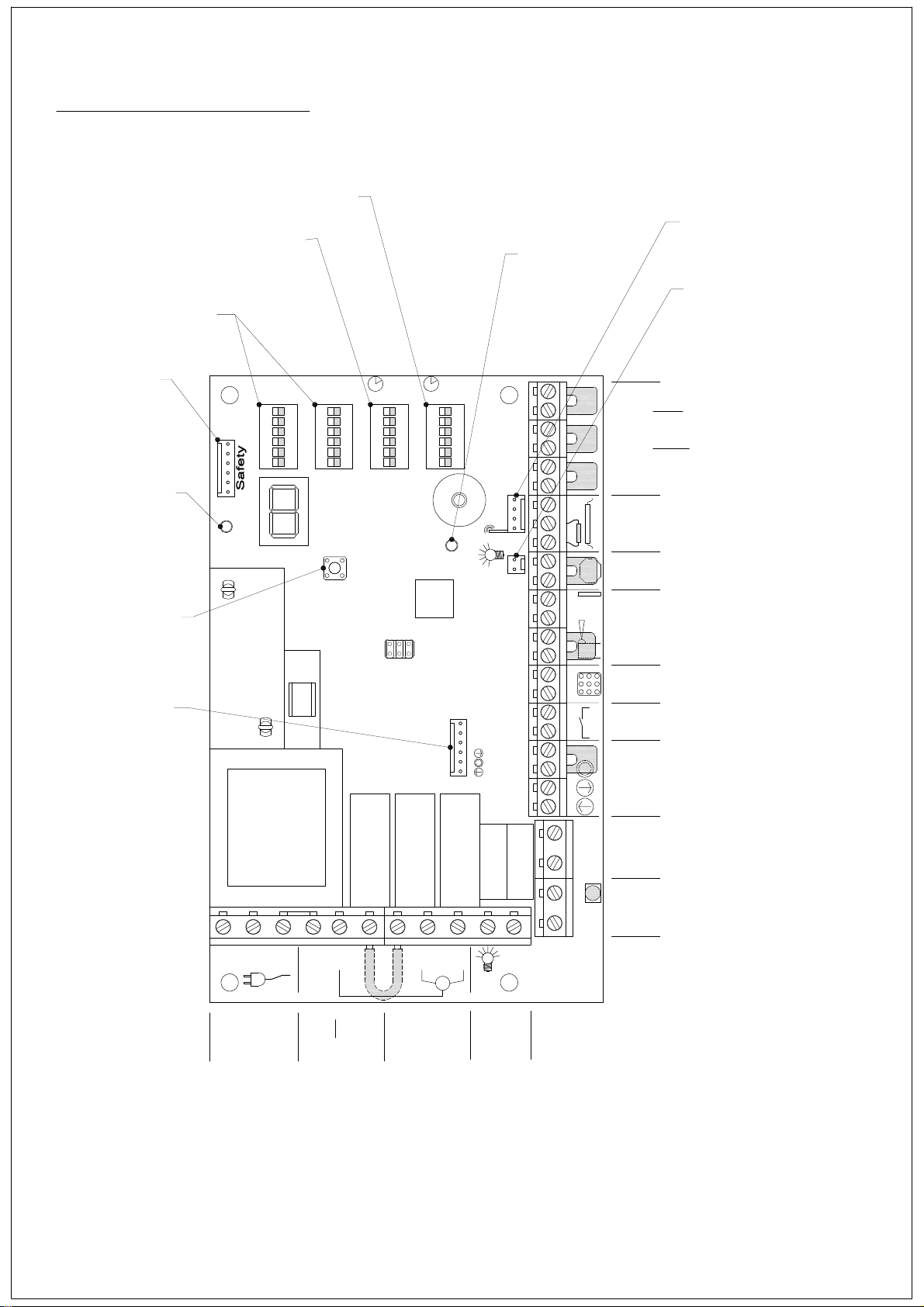
DC2 general connections
Closing Delay
Timer Setting
Run Timer
Settings
Function
Settings
Safety
Module
Power
Indicator
(GREEN)
Transmitter
Programming
Button
Prog II Prog I
DIP4 DIP3 DIP2 DIP1
DIPON
X8
1 2 3 4 5 6
Connector For
Plug in Radio Receiver
Transmitter
Programming
Indicator
(RED)
Connection For
Plug in 24v dc
Courtesy Light
RT CT
DIPON
DIPON
1 2 3 4 5 6
DIPON
1 2 3 4 5 6
1 2 3 4 5 6
X6X7
RC
T1
X5
Independent (N/C) travel limit
Open
switch - OPEN direction
Independent (N/C) travel limit
switch - CLOSE direction
Independent (N/C) pre-close
Lim it Swit ch es
Prelim Close
limit switch
Safety edge connection
resistive 8.2k or optical beam
Sa fet y e d ge
GND SKS 12V
Emergency Stop Button
(N/C)
Emerg
Stop
Photocell
bea m
Ph o to
24v dc supply + N/C
connection
Membrane
Push Button
connection
N L1 PE PE N L C
Motor
230v Connection for Motor
(Not suitable foran Auxiliary
230v Mains Supply
230v Mains Supply)
UP DWN
M
230v Motor Control
or VoltF ree Output
Keypad
Single Impulse Button
(sequential control)
OPEN-STOP-CLOSE-STOP
Push button control
independent direction open
and close + stop
circuit
UP DWN STOP C IMPULSE IN1 IN2 24VGNDNC
X4
Green Traffic Light
OUT1
Pre-warning
Light or Red
Traffic Light
red
Sig n al lig ht
Light
X3
X3X2X1
230V Courtesy
Light
3
Page 4
230 volt Mains Power
N L1
PE
X1
230V
Mains
Supply
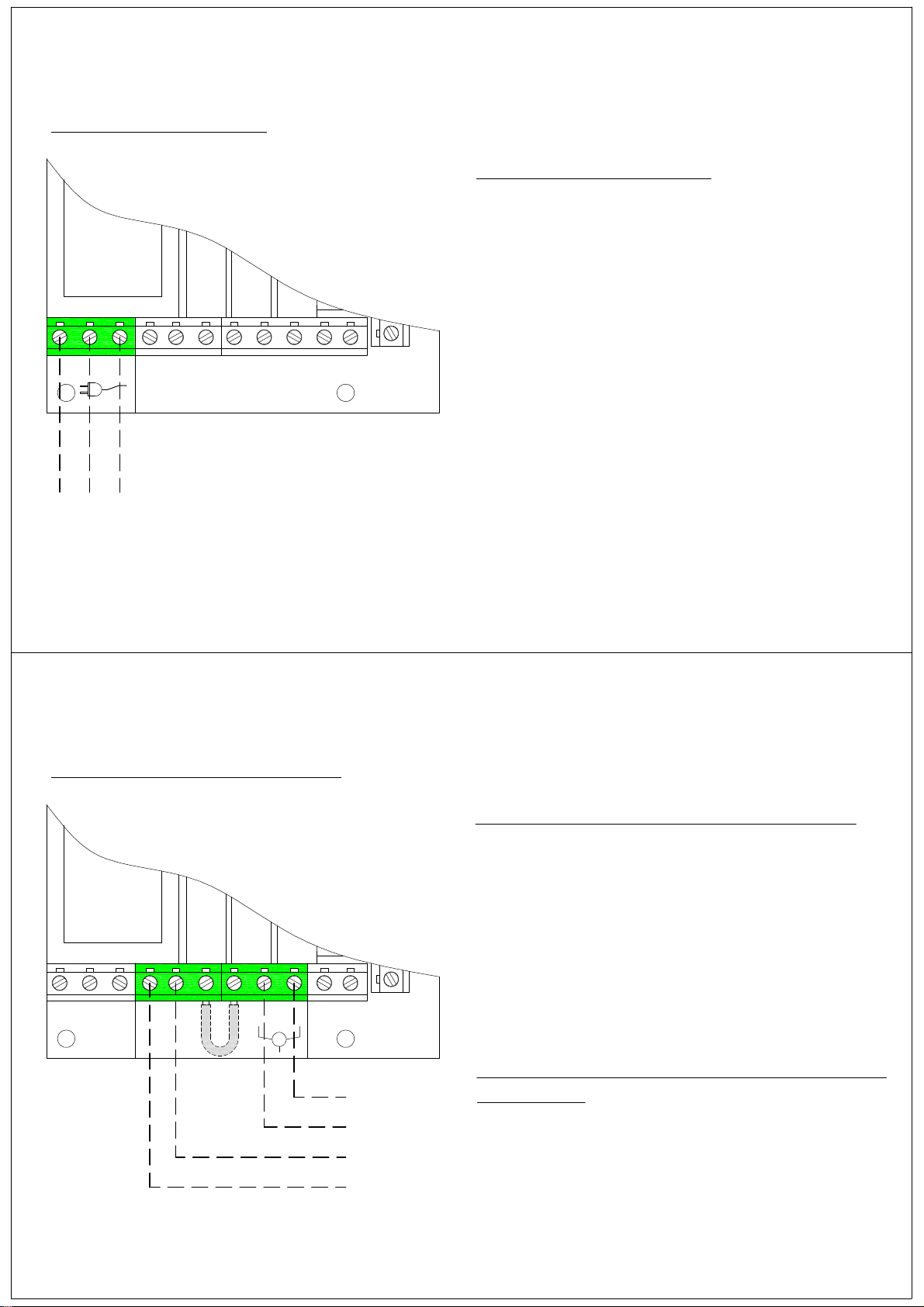
Mains Power Connection
PE = EARTH (Grn/Yel)
L1 = LIVE (Brown)
N = NEUTRAL (Blue)
Use these terminals as a direct connection
for 230v (1ph) Mains supply to the DC2
Controller
This connection should be fused at 13A
(max)
230v Tube Motor Connection
PE N
X2
L C
Motor
UP DWN
M
Black
Brown
Blue
Green / Yellow
}
Connection to a typical 230v Tube Motor
PE = EARTH (Grn/Yel)
N = NEUTRAL (Blue)
UP = OPEN DIRECTION (Brown)
DWN = CLOSE DIRECTION (Black)
Use these terminals as a direct connection
for a tube motor to the DC2 Controller
This unit still requires 230V mains power
to operate
Tube
Motor
4
Page 5
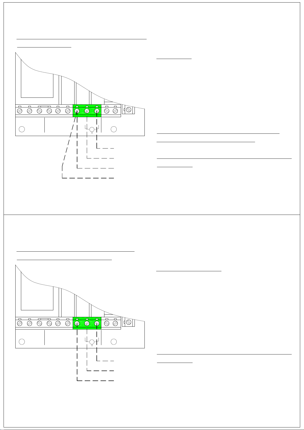
Volt free Connection for 'F' , 'W' and SD
series operators
Connection
X2
Remove factory fitted link
UP DWN
C
M
Yellow
Purple
Red
White
C = COMMON
UP = OPEN DIRECTION
DWN = CLOSE DIRECTION
Use these terminals as a direct connection
to control 'F', 'W' and 'SD' series operators
Jumper Links 'ODM' and 'CDM' must be
removed from the operator PCB
This unit still requires 230V mains power
to operate
Volt Free Connection for 'JM' series
operators and other controls
Remove factory fitted link
UP DWN
C
X2
M
Purple
Yellow
Red
Volt Free Connection
C = COMMON
UP = OPEN DIRECTION
DWN = CLOSE DIRECTION
Use these terminals as a direct connection
to control 'JM' series operators or other
controls
This unit still requires 230V mains power
to operate
5
Page 6
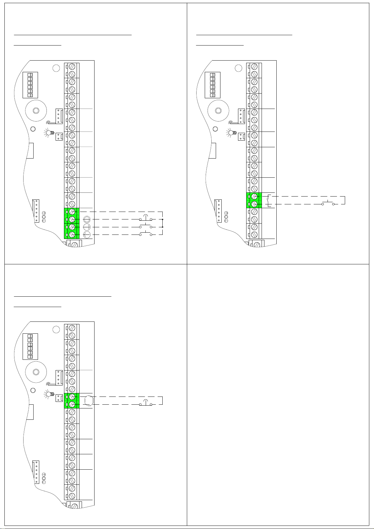
Remote Push Button Control
(If required)
Remote Impulse Button
(If required)
DIP1
DIPON
CT
X5
1 2 3 4 5 6
X6X7
RC
Remove factory fitted link and
connect Push Button Station
Common
Stop
Open
UP DWNSTOP C
Close
CT
DIP1
DIPON
X5
1 2 3 4 5 6
X6X7
RC
IMPULSE
Connect a N/O single Push Button
Station
Operating sequence
OPEN - STOP - CLOSE - STOP
X4
Emergency Stop Button
(If required)
CT
DIP1
DIPON
1 2 3 4 5 6
X6X7
RC
X5
Stop
Remove factory fitted link and
connect a N/C Latching Stop
Button
6
Page 7
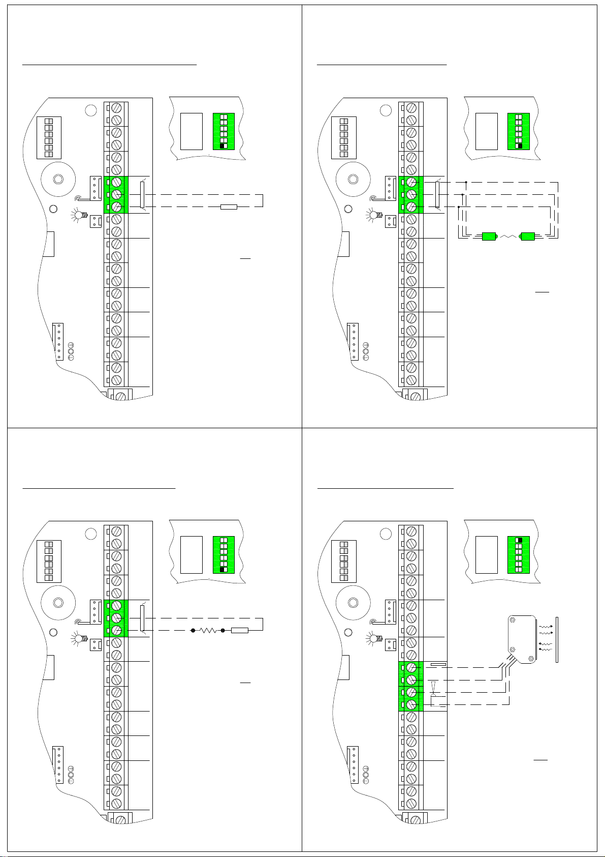
8.2k Resistive Safety Edge
Optical Safety Edge
DIP1
DIPON
CT
Prog II Prog I
X5
1 2 3 4 5 6
X6X7
RC
GNDSKS 12V
Note: Wire colour may vary
Brown
White
Sa f et y edge
Remove factory fitted resistor
and connect safety edge
DIP Switch 1 (prog I) = ON
DIP3
DIPON
1 2 3 4 5 6
8.2k
CT
DIP1
DIPON
1 2 3 4 5 6
X6X7
RC
GNDSKS 12V
Prog II Prog I
X5
Sa f et y edge
Transmitter Receiver
Remove factory fitted resistor and
connect safety edge
DIP Switch 1 (prog I) = OFF
DIP3
DIPON
Brown
Green
White
1 2 3 4 5 6
Pneumatic Safety Edge
CT
DIP1
DIPON
1 2 3 4 5 6
X6X7
RC
X5
Sa fet y e dge
GND SKS 12V
Prog II Prog I
DIP3
DIPON
1 2 3 4 5 6
8.2k Res
Remove factory fitted resistor and
connect in series with Air Switch
DIP Switch 1 (prog I) = ON
N/C Air Switch
Photocell (reflective)
CT
DIP1
DIPON
1 2 3 4 5 6
X6X7
RC
24V
GNDNC
beam
Ph o to
Prog II Prog I
X5
Note: Wire colour may vary
Brown
Blue
White
Black
Remove factory fitted link and
connect Photocell
(N/C contact)
DIP Switch 6 (prog I) = OFF
DIP3
DIPON
1 2 3 4 5 6
7
Page 8
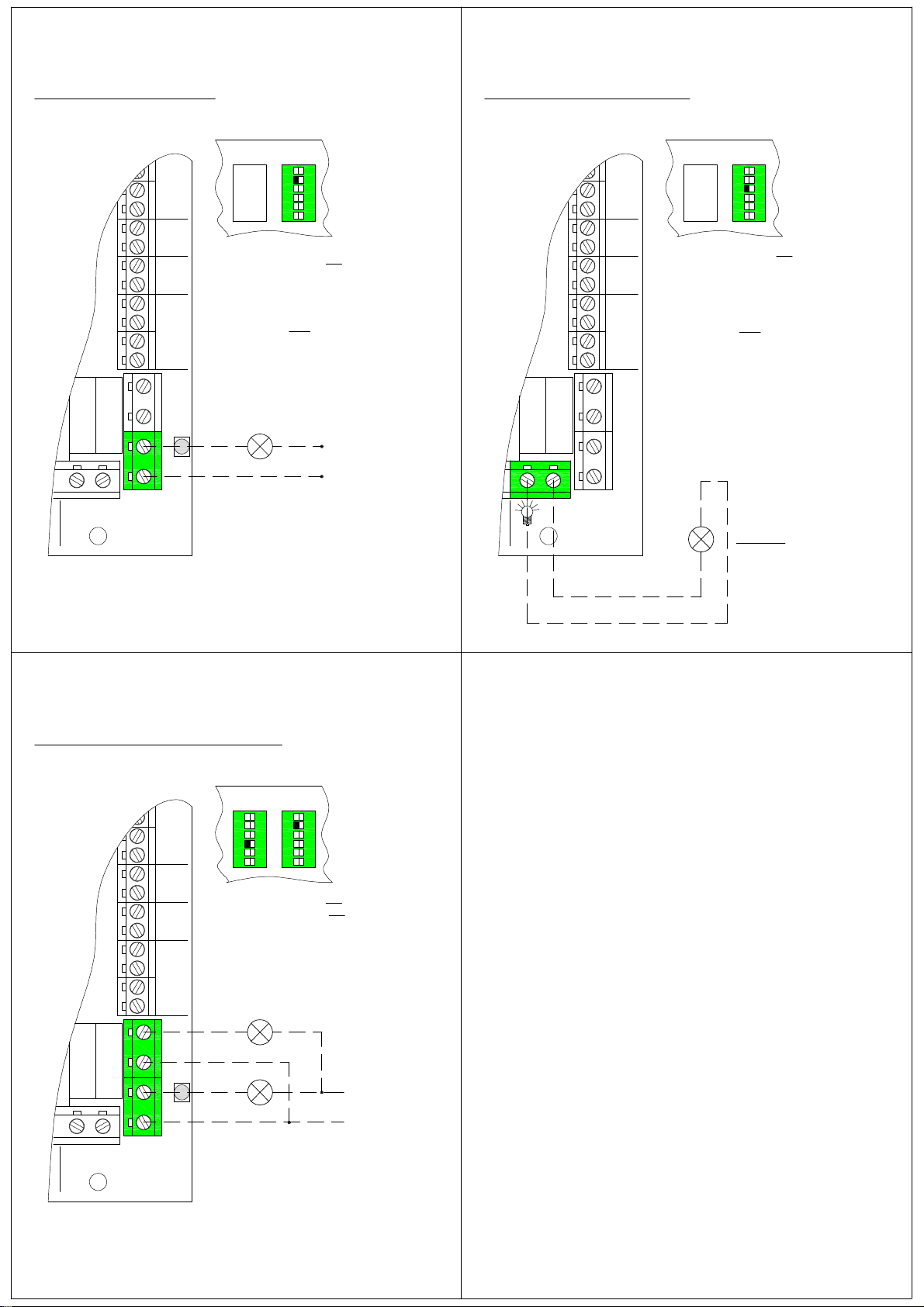
230V Courtesy LightPre-warning Light
Prog II Prog I
DIP3
DIPON
1 2 3 4 5 6
DIP Switch 5 (prog I) = ON
Light flashes for 5 seconds before
the motor operates, then stays on
permanently until the motor stops
DIP Switch 5 = OFF
Pre-warning light function off
Prog II Prog I
DIP3
DIPON
1 2 3 4 5 6
DIP Switch 4 (prog I) = ON
Light is continuously on when the
operator is running, light will switch
off 3 secs after the operator stops
DIP Switch 4 = OFF
Light switches on for 2 minutes
constantly at the start of the
operator
(L) or (+v)
red
S ign al l ig ht
X3
A separate power supply
must be provided to suit the
voltage of the light used
(N) or (0v)
X3
Light
230v light
Red / Green Traffic Light
Prog II Prog I
DIP4 DIP3
DIPON
1 2 3 4 5 6
DIP Switch 5 (prog I) = ON
DIP Switch 3 (prog II) = ON
RED light flashes for 5 seconds
before the motor operates, then
stays on permanently until the
motor stops
GREEN light on when door reaches
top
green
OUT1
red
Si gnal li gh t
X3
red
A separate power supply
must be provided to suit the
voltage of the light used
DIPON
1 2 3 4 5 6
(L) or (+v)
(N) or (0v)
8
Page 9
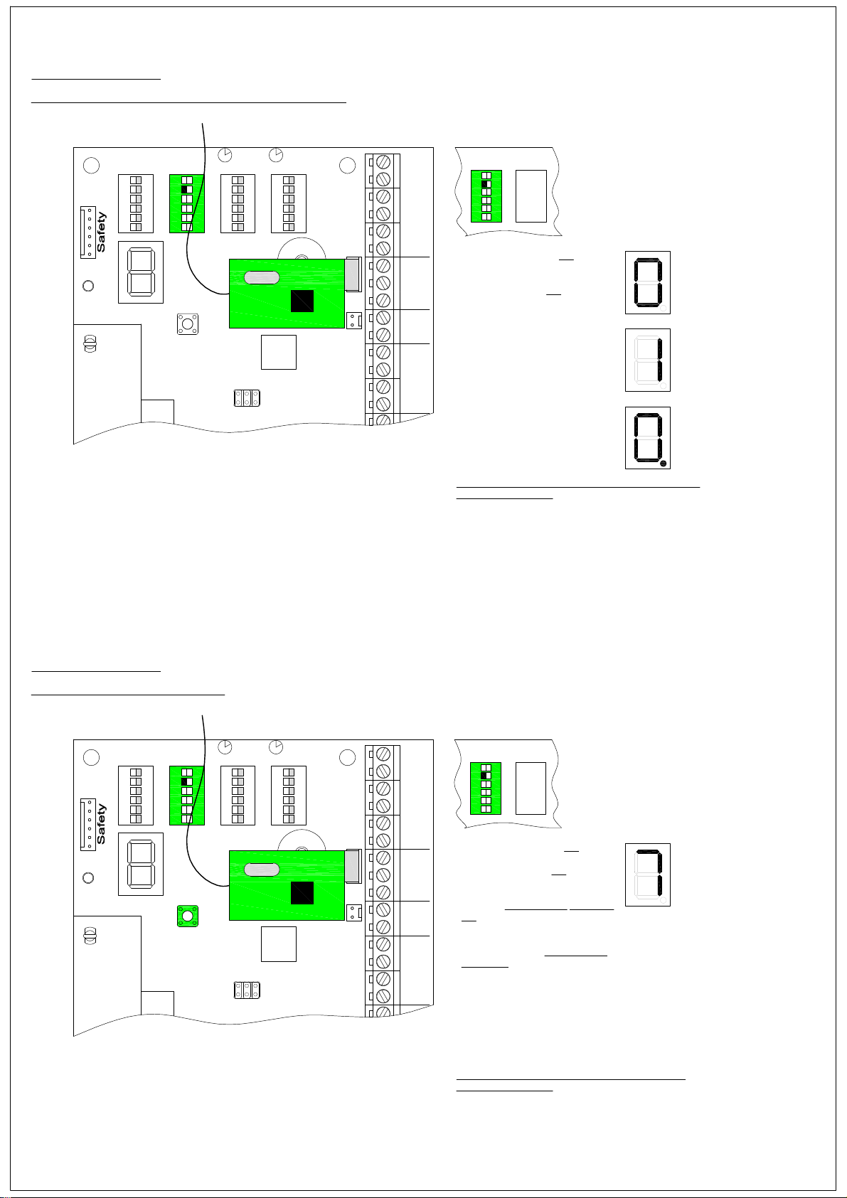
Radio Control
(transmitter programming 20 max)
Prog II Prog I
DIPON
X8
1 2 3 4 5 6
DIP3
DIPON
1 2 3 4 5 6
T1
RT CT
DIPON
DIPON
1 2 3 4 5 6
Prog II Prog I
X5
1 2 3 4 5 6
X6X7
DIP4 DIP3
DIPON
1 2 3 4 5 6
DIP Switch 5 (prog II) = ON
Plug in radio Receiver where shown
Turn DIP switch 5 to ON
The display now shows
Press and hold the button on the
transmitter for 2 second, the DC2
will bleep once
The transmitter is stored and the
display will advance by one digit
this is the next location to be used
Repeat for each transmitter
Number 10 transmitter location will
be shown as thus
Once all transmitters have been entered DIP switch 5
must be switched off
Radio Control
(transmitter deleting)
Prog II Prog I
DIP3
DIPON
X8
DIPON
1 2 3 4 5 6
1 2 3 4 5 6
T1
RT CT
DIPON
DIPON
1 2 3 4 5 6
Prog II Prog I
X5
1 2 3 4 5 6
X6X7
DIP4
DIP Switch 5 (prog II) = ON
Turn DIP switch 5 to ON
The display now shows the last
location to be used e.g.. 7
Using the programming button T1
on the DC2 controller, scroll
through the display to the location
to be deleted
Press and hold the programming
button T1 the DC2 will bleep twice
this location is now empty
Repeat as necessary
Once transmitters have been deleted DIP switch 5
must be switched off
DIP3
DIPON
1 2 3 4 5 6
9
Page 10
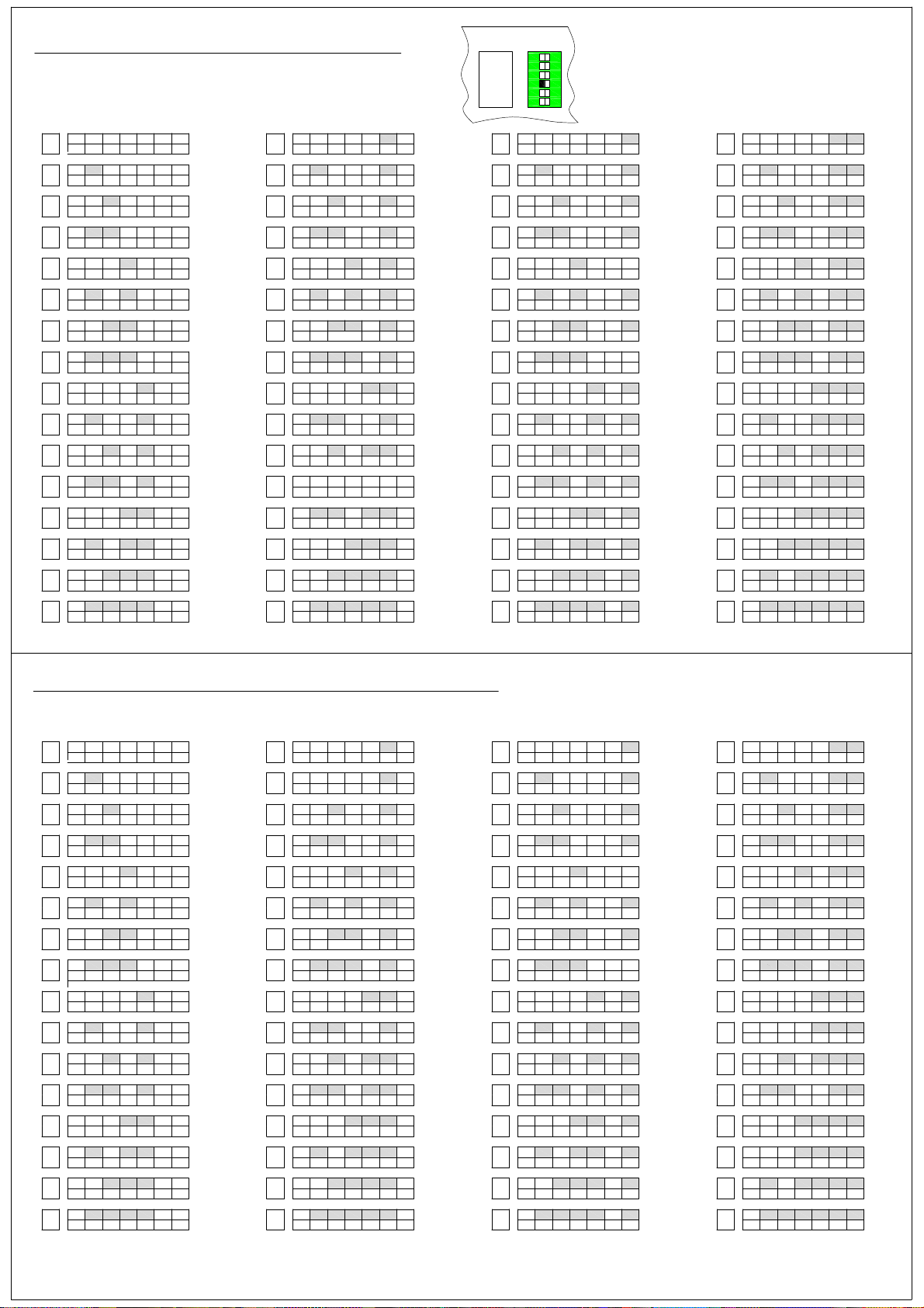
Run Timer Settings (DIP Switch 'RT')
DIP switch 3 (prog I) = ON
Prog II Prog I
DIP4 DIP3
DIPON
1 2 3 4 5 6
ON
OFF
OFF 1
2 3 4 5 6
ON
1
7"
OFF
2 3 4 5 6
ON
10"
13"
16"
19"
22"
25"
28"
31"
34"
37"
40"
43"
46"
49"
2
OFF
1 3 4 5 6
ON
1
2
OFF
ON
OFF
1
2 4 5 6
ON
1
OFF
2 4
ON
OFF
1
ON
1
OFF
ON
OFF 1 2 3 5 6
ON
1 4
OFF 2 3 5 6
ON
2 4
OFF 1 3 5 6
ON
2 41
OFF 3 5 6
ON
OFF 1 2 5 6
ON
1
OFF 2 5 6
ON
2 3
OFF 1 5 6
ON
1 2 3
OFF 5 6
3 4 5 6
3
3
5 6
32
4 5 6
32
4 5 6
4
4
3
4
3
4
4
ON
52"
OFF 1 2 3 4 6
ON
55"
58"
61"
64"
67"
70"
73"
76"
79"
82"
85"
88"
91"
94"
97"
1
OFF 2 3 4 6
ON
2
OFF 1 3 4 6
ON
1
2
OFF 3 4 6
ON
OFF 1 2 4 6
ON
1
OFF
2 4
ON
2
OFF 1 4 6
ON
1
2
OFF 4 6
ON
OFF 1 2 3 6
ON
1
2
OFF 3 4 6
ON
2
OFF 1 3 6
ON
OFF 1 2 3 4 5 6
ON
1
2
OFF 3 6
ON
OFF 1 2 6
ON
2
OFF 1 6
ON
1
2
OFF 6
5
5
5
5
5
3
5
3
3
3
3
3
6
5
5
5
4
5
5
4
5
4
53 4
5
4
5
4
100"
103"
106"
109"
112"
115"
118"
121"
124"
127"
130"
133"
136"
139"
142"
145"
ON
OFF
1 2 3 4 5
ON
1
OFF
2 3 4 5
ON
OFF
123 4 5
ON
1 2
OFF
ON
OFF
1 234 5 6
ON
123
OFF
ON
2 3
OFF
1
ON
1 2 3
OFF
ON
OFF
1 2 345
ON
1
OFF
2 345
ON
OFF
12345
ON
1 23456
OFF
ON
OFF
1 2 345 6
ON
1
OFF
2 5
ON
2 4
OFF
1
ON
OFF
3 4 5
3
3
3 62 41 3 62 41 5
5
4
4 5
4 5 6
4 63
5
5
6
6
6
6
6
6
6
6
6
6
6
148"
151"
154"
157"
160"
163"
166"
169"
172"
175"
178"
181"
184"
187"
190"
193"
ON
OFF
ON
OFF
ON
OFF
ON
OFF
ON
OFF
ON
OFF
ON
OFF
ON
OFF
ON
OFF
ON
OFF
ON
OFF
ON
OFF
ON
OFF
ON
OFF
ON
OFF
ON
OFF
1 2 3 4
2 3 4
1 3 4
3 4
3 65
1 2 4
3 61 5
2 4
3 62 5
1 4
3 621 5
1 2 3
2 3
1 3
3
3 64 5
1 2
3 62 4 5
1
3 641 5
2
65
615
62 5
621 5
4
64 5
641 5
62 4 5
62 41 5
Closing Delay Timer Settings (DIP Switch 'CT')
ON
OFF
OFF 1
2 3 4 5 6
ON
1
5"
OFF
2 3 4 5 6
ON
7"
9"
11"
13"
15"
17"
19"
21"
23"
25"
27"
29"
31"
33"
2
OFF
1 3 4 5 6
ON
1
2
OFF
ON
OFF
1
2 4 5 6
ON
1
OFF
2 4 5 6
ON
OFF
1
ON
1
OFF
ON
OFF 1 2 345 6
ON
OFF12 345 6
ON
OFF 12345 6
ON
1 234
OFF
ON
OFF 1 2
ON
OFF12
ON
2 3 4
OFF 1
ON
1 2 3 4
OFF
3 4 5 6
3
3
32
4 5 6
32
4 5 6
5 6
3 4
5 6
3 4
5 6
5 6
5 6
ON
35"
OFF 1 2 3 456
ON
37"
OFF12 3 456
ON
39"
OFF 123 456
ON
41"
43"
45"
47"
49"
51"
53"
55"
57"
59"
61"
63"
65"
1 2
OFF
ON
OFF 1 23456
ON
OFF123456
ON
2 345
OFF 1
ON
1 2 345
OFF
ON
OFF 1 2 3 6
ON
2 51
OFF 3 4 6
ON
2 54
OFF 1 3 6
ON
2 541
OFF 3 6
ON
OFF 6
1 2
ON
OFF 2 6
ON
OFF 1 6
ON
OFF 6
3 456
6
6
54
543
43 51
5432
54321
ON
67"
OFF
1 2 3 4 5
ON
69"
71"
73"
75"
77"
79"
81"
83"
85"
87"
89"
91"
93"
95"
97"
1
OFF
2 3 4 5
ON
2
OFF
1 3 4 5
ON
1
2
OFF
ON
OFF
1 2 4 5 6
ON
1
OFF
2 4 5
ON
2
OFF
1 4 5
ON
1
2
OFF
ON
OFF
1 2 3 5
ON
1
OFF
2 3 5
ON
2
OFF
1 3 5
ON
1
2
OFF
ON
OFF
1 2
ON
1
OFF
2 5
ON
2
OFF
1
ON
OFF
3 4 5
3
3
3
3
3 5
3 456
3
3
4 5 6
4
4
4
4
4
4
5
5
6
6
6
6
6
6
6
6
6
6
6
6
62 3 41
99"
101"
103"
105"
107"
109"
111"
113"
115"
117"
119"
121"
123"
125"
127"
129"
ON
OFF
1 2 3 4
ON
1
OFF
2 3 4
ON
OFF
123 4
ON
1 2
OFF
ON
OFF
1 234
ON
12345 6
OFF
ON
2 3
OFF
1
1
ON
2 345 6
OFF
ON
OFF
1 2 3
ON
1
OFF
2 3
ON
OFF
123
ON
1 234 5 6
OFF
ON
OFF
1 2
ON
2 3 4 5 6
OFF
1
ON
123 4 5 6
OFF
ON
OFF
5 6
5
5 6
5 6
3 4
5 6
5
4
4 5 6
4 5 6
4 5 6
3 4 5 6
6
6
61 3 4 52
10
Page 11
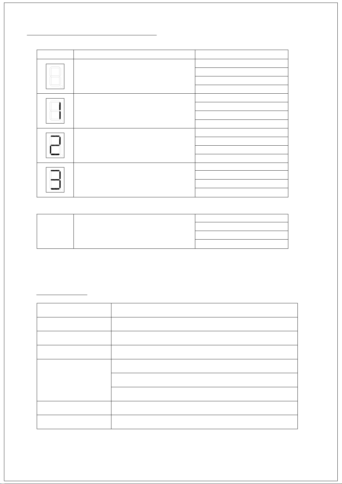
Trouble shooting - Common Faults
Display
Other
Fault Check
Blank -No Power
Emergency Stop Activated
Safety Edge Activated
Photocell Activated
or open circuit
Radio Control opens door
but will not close
Mains Fuse
PCB Fuse
Mains Power Supply
Factory Fitted Link
Release E-Stop Button
DIP Switch Position
Factory Fitted Resistor
Wiring or Loose Connections
Repalce sensors
DIP Switch Position
Photocell alignment
Wiring or Loose Connections
Repalce photocell
DIP Switch Position
Photocell faulty or miss aligned
Wiring or Loose Connections
Faulty Safety Edge
Technical data
Model DC 2 - EURO delux
Supply Voltagel
Frequency
Protection class
Outputs motor
Wiring size (max)
Operature temp
230VAC
50Hz
IP54
3x NO relay contact 230V / 5A
2x NO relay contact 230V / 2A
1x unregulated supply voltage 24V DC max 50mA
1.5mm² max
-10°C to +55°C
11
Page 12

12
ellard Ltd
Roundthorn Ind Est
Dallimore Road
Wythenshawe
Manchester M23 9NX
Tel: 0161 945 4561
Fax: 0161 945 4566
 Loading...