

Ellard CITY1-EVO, CITY1-EVO-120V User Manual

INDEX
1 - IMPORTANT REMARKS .........................................................................................................................................
2 - DISPOSAL ...............................................................................................................................................................
3 - EU DECLARATION OF CONFORMITY ....................................................................................................................
4 - TECHNICAL SPECIFICATIONS ................................................................................................................................
5 - DESCRIPTION OF THE CONTROL UNIT .................................................................................................................
5.1 - ELECTRIC CONNECTIONS ................................................................................................................................
5.2 - PLUG IN RECEIVER ..........................................................................................................................................
6 - CONTROL PANEL ..................................................................................................................................................
6.1 - USE OF DOWN MENU AND UP KEYS FOR PROGRAMMING ............................................................................
7 - QUICK CONFIGURATION ......................................................................................................................................
8 - LOADING DEFAULT PARAMETERS .......................................................................................................................
9 - SELF-LEARNING OF WORKING TIMES .................................................................................................................
16
16
ENGLISH
16
17
17
18
18
20
20
21
21
21
10 - EMERGENCY DEAD MAN OPERATION ..............................................................................................................
11 - PROGRAMMING THE CONTROL UNIT ...............................................................................................................
12 - OPERATION DEFECTS .........................................................................................................................................
23
23
28
m ATTENTION
THIS QUICK GUIDE IS ONLY USED TO START THE AUTOMATION IN ITS
BASIC CONFIGURATION. THE FULL MANUAL IS AVAILABLE ON THE V2
WEBSITE (www.v2home.com)
- 15 -

1 - IMPORTANT REMARKS
For any installation problem please contact our Customer Service
at the number +39-0172.812411 operating Monday to Friday
from 8:30 to 12:30 and from 14:00 to 18:00.
V2 has the right to modify the product without previous
notice; it also declines any responsibility to damage or
injury to people or things caused by improper use or wrong
installation.
ENGLISH
m Please read this instruction manual very carefully
before installing and programming your control unit.
• This instruction manual is only for qualified technicians, who
specialize in installations and automations.
• The contents of this instruction manual do not concern the end
user.
• Every programming and/or every maintenance service should
be done only by qualified technicians.
AUTOMATION MUST BE IMPLEMENTED IN COMPLIANCE
WITH THE EUROPEAN REGULATIONS IN FORCE:
EN 60204-1 (Machinery safety. electrical equipment of
machines, part 1: general rules)
EN 12445 (Safe use of automated locking devices,
test methods)
EN 12453 (Safe use of automated locking devices,
requirements)
2 - DISPOSAL
As for the installation operations, even at the end of this product’s
life span, the dismantling operations must be carried out by
qualified experts.
This product is made up of various types of materials: some can
be recycled while others need to be disposed of.
Find out about the recycling or disposal systems envisaged by your
local regulations for this product category.
Important! – Parts of the product could contain pollutants or
hazardous substances which, if released into the environment,
could cause harmful effects to the environment itself as well as to
human health.
As indicated by the symbol opposite, throwing away this product
as domestic waste is strictly forbidden. So dispose of it as
differentiated waste, in accordance with your local regulations,
or return the product to the retailer when you purchase a new
equivalent product.
Important! – the local applicable regulations may envisage heavy
sanctions in the event of illegal disposal of this product.
• The installer must provide for a device (es. magnetotermical
switch) ensuring the omnipolar sectioning of the equipment
from the power supply. The standards require a separation of
the contacts of at least 3 mm in each pole (EN 60335-1).
• After making connections on the terminal board, use one
hose clamp to fix dangerous voltage wires near the terminal
board and another hose clamp to fix safety low voltage wires
used for accessories connection; this way, in case of accidental
detachment of a conducting wire, dangerous voltage parts will
not come into contact with safety low voltage ones.
• The plastic case has an IP55 insulation; to connect flexible or
rigid pipes, use pipefittings having the same insulation level.
• Installation requires mechanical and electrical skills, therefore it
shall be carried out by qualified personnel only, who can issue
the Compliance Certificate concerning the whole installation
(EEC Machine Directive 89/392, Annex IIA).
• The automated vehicular gates shall comply with the following
rules: EN 12453, EN 12445, EN 12978 as well as any local rule
in force.
• Also the automation upstream electric system shall comply with
the laws and rules in force and be carried out workmanlike.
• The door thrust force adjustment shall be measured by means
of a proper tool and adjusted according to the max. limits,
which EN 12453 allows.
• We recommend to make use of an emergency button, to be
installed by the automation (connected to the control unit
STOP input) so that the gate may be immediately stopped in
case of danger.
• Always remember to connect the earth according to current
standards (EN 60335-1, EN 60204-1).
3 - EU DECLARATION OF CONFORMITY
V2 S.p.A. hereby declare that CITY1-EVO products conform to the
essential requirements established in the following directives:
• 2014/30/UE (EMC Directive)
• 2014/35/UE (Low Voltage Directive)
• ROHS2 2011/65/CE
Racconigi, 01/06/2015
V2 S.p.A. legal representative.
Giuseppe Pezzetto
- 16 -
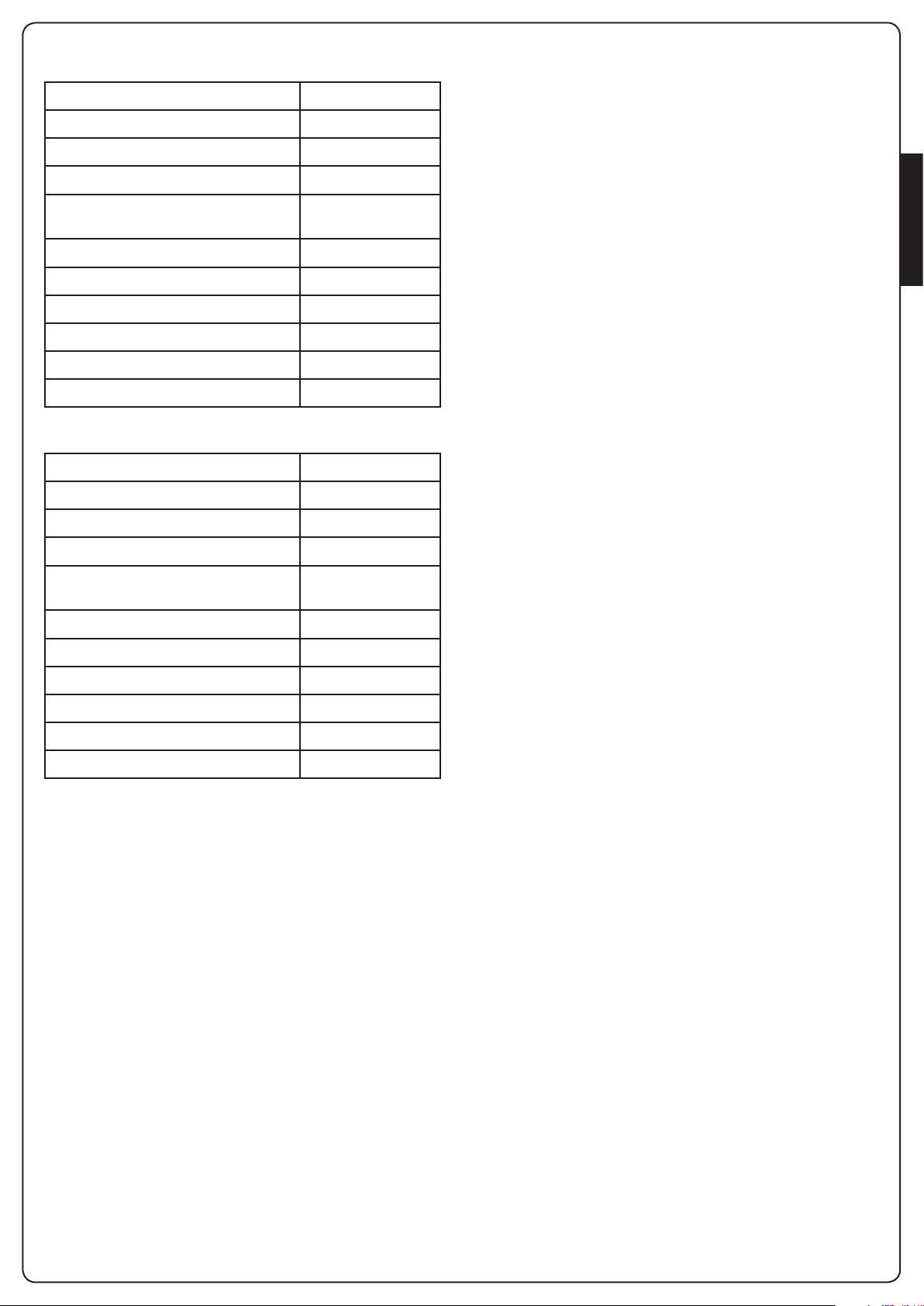
4 - TECHNICAL SPECIFICATIONS 5 - DESCRIPTION OF THE CONTROL
UNIT
CITY1-EVO
Power supply 230V / 50Hz
Max motors load 2 x 700W
The digital control unit CITY1-EVO is an innovative V2 product
that guarantees a safe and reliable automation of leaf swing or
sliding gates.
Duty clcle 40%
Consumption in stand-by
(with LOW ENERGY module installed)
Max accessories load 24V 10W
Protection fuse 5A
Weight 1600 g
Dimensions 295 x 230 x 100 mm
Working temperature -20 ÷ +60°C
Protection IP55
Power supply 120V / 60Hz
Max motors load 2 x 500W
Duty clcle 30%
Consumption in stand-by
(with LOW ENERGY module installed)
Max accessories load 24V 10W
Protection fuse 8A
Weight 1600 g
Dimensions 295 x 230 x 100 mm
Working temperature -20 ÷ +60°C
Protection IP55
0,45 W
CITY1-EVO-120V
0,45 W
CITY1-EVO is provided with a display that, not only makes
programming simple, but also allows a continuous monitoring of
the input statuses; in addition, thanks to a menu structure, the
working schedule and the operation logic can be set easily.
In compliance with the European standards concerning electrical
safety and electromagnetic compatibility (EN 60335-1,
EN 50081-1 and EN 50082-1) it has been equipped with the low
voltage circuit total electric insulation (motors included) from the
network voltage.
Other characteristics:
• Automatic control for the null current relay switch
• Allows to control ENCODER-equipped 230V motors
• Power adjustment with independent wave shutting on both
the two motors
• Obstacle detection by means of monitoring start condenser
voltage
• Automatic learning of the operation time
• Operation by means of mechanical ends of stroke connected to
the gearcase or connected in series to the motor
• Tests for safety devices (photocells, safety edges and triacs)
before each opening (as required by the referred regulations)
• Deactivation of safety inputs through the configuration menu:
no jumper is required for terminals concerning safety devices
that have not been installed, yet. You will only need to disable
this function from its relevant menu
• Control unit programming can be locked through the optional
CL1+ key
• ADI 2.0 connector for the advanced management of the ADI
devices.
• USB connector to connect the control unit to a PC and manage
through software the programming of the unit, the firmware
updates and the operation diagnostics.
• Connector for the LOW ENERGY module that allows saving
electrical energy: when the gate is standing the LOW ENERGY
module deactivates the display, the photocells and all the
devices power supplied by a terminal box.
To activate the operation of the module, it is necessary to
activate the ENERGY SAVING function (parameter EnSA = Si).
ENGLISH
- 17 -
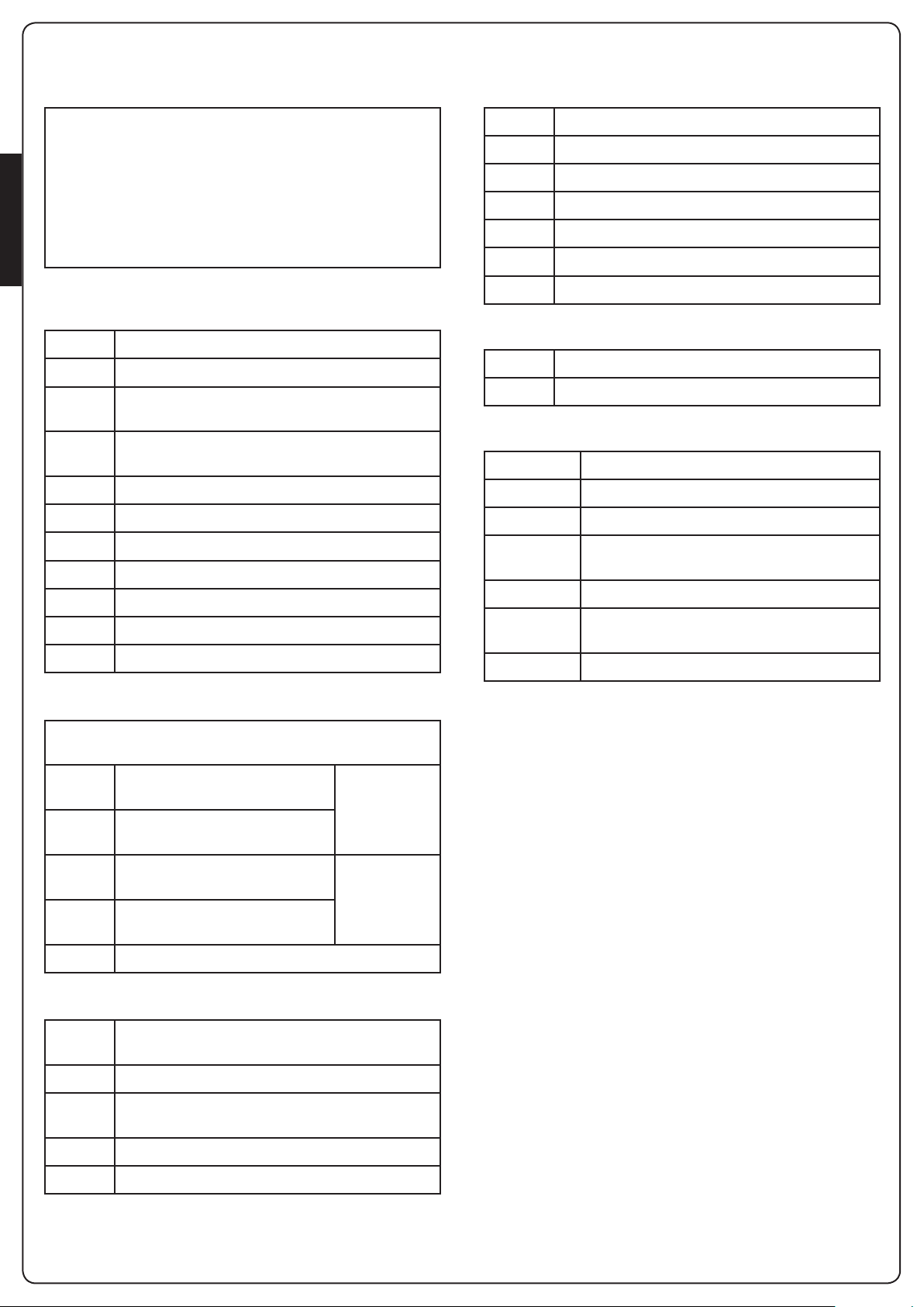
5.1 - ELECTRIC CONNECTIONS
m WARNING: The installation of the unit, safety
devices and accessories must be carried out when the
power supply is disconnected
BEFORE PROCEEDING WITH THE ELECTRICAL
CONNECTIONS, READ CAREFULLY THE CHAPTERS
DEDICATED TO THE INDIVIDUAL DEVICES AVAILABLE IN
ENGLISH
THE PAGES THAT FOLLOW.
L1 Antenna
L2 Antenna shielding
L3 START - Opening control for the connection of
control devices with N.O. contact
L4 START P. - Opening controls for pedestrian access for
the connection of control devices with N.O. contact
L5 STOP - Stop command. N.C. contact
L6 Common (-)
L7 FOT1 - Photocells type 1. N.C. contact
L8 FOT2 - Photocells type 2. N.C. contact
L9 COS1 - Safety edges type 1. N.C. contact
L10 COS2 - Safety edges type 2. N.C. contact
L11 Common (-)
H1 - H2 Flashing light 230 / 120 Vac - 40W
H3 Motor M2 (OPENING)
H4 Motor M2 (COMMON)
H5 Motor M2 (CLOSING)
H6 Motor M1 (OPENING)
H7 Motor M1 (COMMON)
H8 Motor M1 (CLOSING)
L Power phase 230V / 120V
N Neutral 230V / 120V
RM MR receiving modules
ADI 2.0 ADI 2.0 interface
USB USB connector
OVERLOAD It shows that there is an overload on accessories
power supply
MAINS It shows that the control unit is power supplied
F1 5 A (230V versions)
8 A (120V versions)
J1 - J2 - J3 Connectors for the LOW ENERGY module
REFER TO THE COMPLETE MANUAL TO CONFIGURE THESE
DEVICES
E1 FCA1 - Open limit switch
motor M1
E2 FCC1 - Close limit switch
motor M1
E3 FCA2 - Open limit switch
motor M2
E4 FCC2 - Close limit switch
motor M2
E5 Common (-)
Z1 Power output 24 Vac for photocells and other
accessories
Z2 Common for accessories power supply
Z3 Photocell/optical edge TX power supply for
functional test
Z4 - Z5 Lock 12V
Z5 - Z6 Low voltage light (12Vdc - 3W)
Encoder
motor M2
Encoder
motor M1
5.2 - PLUG IN RECEIVER
CITY1-EVO is suitable for plugging in a Personal Pass MR receiver.
m WARNING: Pay attention to the way you connect the
removable modules.
MR1 module receiver is provided with 4 channels and each of
them is suitable for a command of CITY1-EVO control unit::
• CHANNEL 1 g START
• CHANNEL 2 g PEDESTRIAN START
• CHANNEL 3 g STOP
• CHANNEL 4 g COURTESY LIGHT
The transmitter codes can be stored in two ways:
1. By pressing the P1 button on the MR receiver (read the
instructions supplied with the receiver)
2. Using WINPPCL software: to run the program you need to
connect a PC to the control unit. The connection can be made
via USB using a standard USB cable.
- 18 -
 Loading...