

Elkron wl31, wl31tg User Manual
1/32 WL31
IS0244-AA
User’s manual
GB
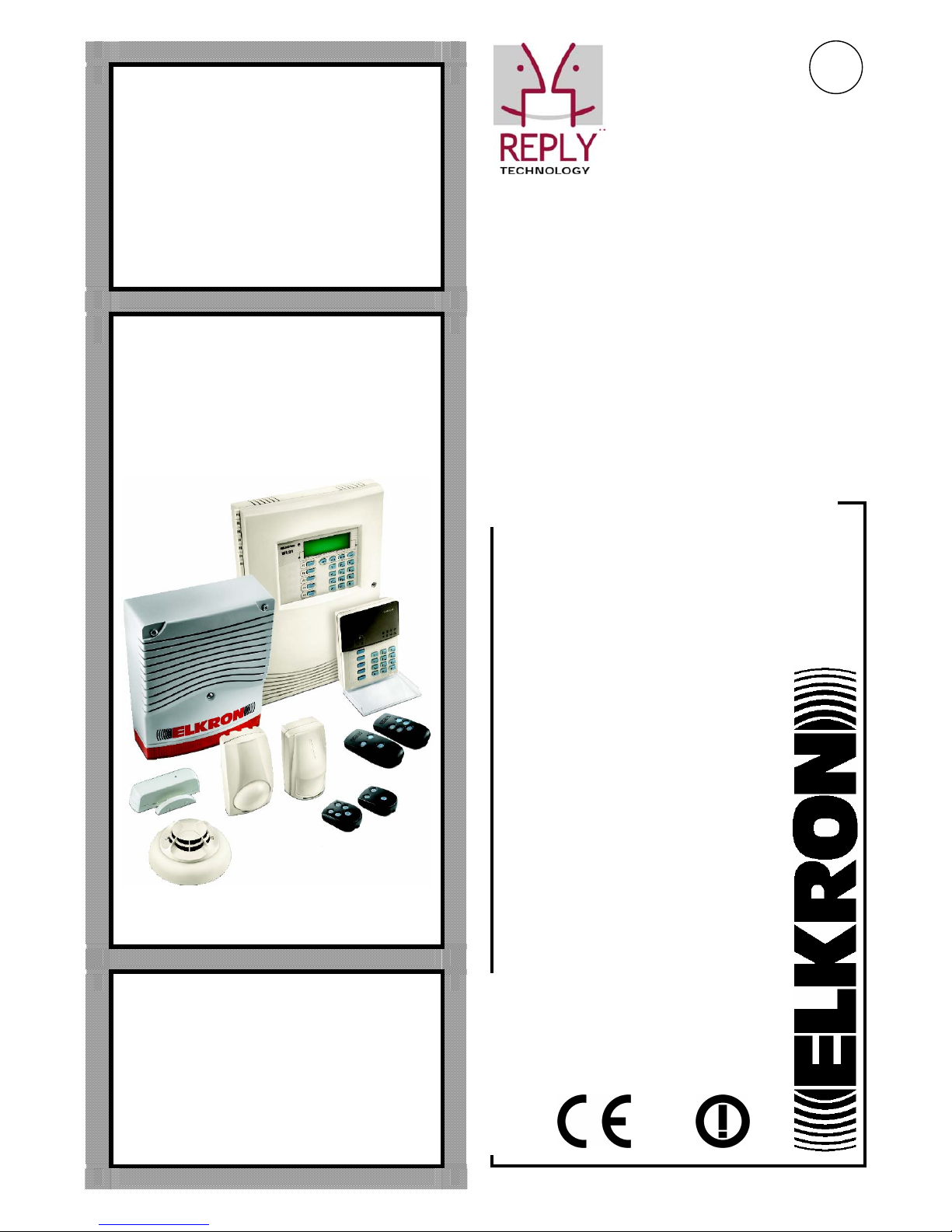
WL31
WL31TG
Bidirectional wireless system
0681
All information included in this document has been collected and carefully verified; nevertheless Elkron S.p.A.
can not be held responsible for possible mistakes and omissions.
Elkron S.p.A. reserves the right to modify or improve at any time and without notice the products described in
this manual.
It is also possible that this manual contains references or information related to products (hardware or
software) or services not yet on the market. Such references or information does not, in any way, mean that
Elkron S.p.A. intends to sell such products or services.
Reply Technology® and Elkron are registered trade marks of Elkron S.p.A.
All trade marks mentioned in this document belong to the relating owners.
© Copyright Elkron S.p.A. 2007
All rights reserved. Partial or total reproduction of this document is only authorized in order to install the
Wireless WL31 system.
Via G. Carducci, 3 – 10092 Beinasco (TO) – ITALY
Tel. +39 (0)11.3986711 – Fax +39 (0)11.3499434
www.elkron.it
– e-mail: info@elkron.it

3/32 WL31
CONTENTS
CONTENTS ..................................................................................................................................................................3
1.0 DESCRIPTION OF THE CENTRAL UNIT KEYBOARD .......................................................................................5
1.1 FUNCTION KEYS PERSONALIZING LABELS...................................................................................................5
1.2 MEANING OF THE ICONS..................................................................................................................................6
1.3 INFORMATION ON THE SYSTEM’S STATUS ...................................................................................................7
1.3.1 SYSTEM’S STATUS (FOR EXAMPLE REFERRING TO A SYSTEM WITH FOUR SECTORS) ...............7
1.3.2 BATTERIES’ STATUS..................................................................................................................................7
1.3.3 HOW TO DISPLAY A SIGNAL IN DETAIL...................................................................................................7
1.3.4 HOW TO DISPLAY AN ALARM MEMORY IN DETAIL ...............................................................................7
1.4 FUNCTION KEYS PROGRAMMING ..................................................................................................................8
2.0 DESCRIPTION OF THE REMOTE KEYBOARD...................................................................................................9
2.1 PROGRAMMABILITY OF THE REMOTE KEYBOARD FUNCTION KEYS ......................................................10
3.0 REMOTE CONTROL DESCRIPTION..................................................................................................................11
3.1 MEANING OF THE LEDS..................................................................................................................................11
3.2 REMOTE CONTROL KEYS FACTORY PROGRAMMING...............................................................................11
3.3 FUNCTIONS WHICH CAN BE ALLOCATED TO THE FUNCTION KEYS ........................................................12
4.0 USING THE SYSTEM ..........................................................................................................................................13
4.1 ACTIVATING THE SYSTEM FROM THE CENTRAL UNIT KEYBOARD..........................................................13
4.1.1 THROUGH ONE OF THE FUNCTIONS OF THE CASCADING MENU....................................................13
4.1.2 THROUGH THE FUNCTION KEYS...........................................................................................................13
4.2 DEACTIVATING THE SYSTEM FROM THE CENTRAL UNIT KEYBOARD.....................................................14
4.2.1 THROUGH ONE OF THE FUNCTIONS OF THE CASCADING MENU....................................................14
4.2.2 THROUGH THE FUNCTION KEYS...........................................................................................................14
4.3 ACTIVATING THE SYSTEM FROM A REMOTE KEYBOARD .........................................................................15
4.4 DEACTIVATING THE SYSTEM FROM A REMOTE KEYBOARD ....................................................................15
5.0 ACCESS TO THE CENTRAL UNIT MENU .........................................................................................................16
5.1 USED CONVENTIONS .....................................................................................................................................16
5.2 MENU KEYS FUNCTIONS................................................................................................................................16
5.3 SYSTEM ACCESS CODE.................................................................................................................................16
MASTER CODE..................................................................................................................................................16
USER CODE .......................................................................................................................................................16
5.4 HOW TO ACCESS THE CASCADING MENU ..................................................................................................17
5.5 HOW TO QUICKLY ACCESS A MENU ITEM ...................................................................................................17
5.6 CENTRAL UNIT MENU .....................................................................................................................................17
6.0 FUNCTIONS.........................................................................................................................................................18
ACTIVATION ..............................................................................................................................................................18
ACTIVATION [0]......................................................................................................................................................18
DEACTIVATION.........................................................................................................................................................18
DEACTIVATION [1].................................................................................................................................................18
EVENT MEMORY.......................................................................................................................................................18
EVENT MEMORY [2] ..............................................................................................................................................18
EVENT MEMORY - READ MEMORY [20] ..............................................................................................................18
SETTING ....................................................................................................................................................................19
SETTINGS [3]..........................................................................................................................................................19
SETTINGS - EXCLUDE/INCLUDE [30]...................................................................................................................19
SETTINGS - TIME AND DATE [31] .........................................................................................................................19
TIME AND DATE - SET TIME [310].........................................................................................................................20
TIME AND DATE - SET DATE [311]........................................................................................................................20
SETTING - LANGUAGE [32]...................................................................................................................................20
LANGUAGE - SELECT LANGUAGE [320]..............................................................................................................20

4/32 WL31
SETTING
- CHANGE CODE [33] ............................................................................................................................20
SETTING - USERS [34]...........................................................................................................................................20
SETTINGS - CONTROL DELAY [35] ......................................................................................................................21
ENGAGING ................................................................................................................................................................21
ENGAGING [4] ........................................................................................................................................................21
ENGAGING - AUXILIARY USERS [40] ...................................................................................................................21
ENGAGING - TECHNICIAN [41] .............................................................................................................................21
ENGAGING - TIME CONTROLS [42]......................................................................................................................21
ENGAGING - ADVANCED SETTINGS [43] ............................................................................................................22
ADVANCED SETTINGS - TECHNICAL ACCESS [430] .........................................................................................22
ADVANCED SETTINGS - REMOTE ACCESS [431]...............................................................................................22
ADVANCED - DEACTIV. REMOTE [432]................................................................................................................22
TEST...........................................................................................................................................................................22
TEST [5] ..................................................................................................................................................................22
TEST - INPUTS [50] ................................................................................................................................................22
TEST - FIRE DET. [51] ............................................................................................................................................23
OUTPUTS - TEST [52] ............................................................................................................................................23
TEST - ADVANCED [53] .........................................................................................................................................23
TELEPHONIC TRX ....................................................................................................................................................24
TELEPHONE NUMBERS [90].................................................................................................................................24
7.0 TELEPHONIC TRX FUNCTIONS ........................................................................................................................24
7.1 CALLS CYCLE LOCK........................................................................................................................................24
7.2 FUNCTIONS ALLOCATED TO THE “FUNCTION” KEY OF THE CENTRAL UNIT KEYBOARDS ...................24
7.2.1 REMOTE COMMUTATION........................................................................................................................25
8.0 YOUR SYSTEM....................................................................................................................................................26
8.1 FUNCTIONS ALLOCATED TO THE “FUNCTION” KEY OF THE CENTRAL UNIT KEYBOARDS ...................26
8.2 FUNCTIONS ALLOCATED TO THE “FUNCTION” KEY OF THE REMOTE CONTROLS AND OF THE
REMOTE KEYBOARDS..........................................................................................................................................27
5/32 WL31
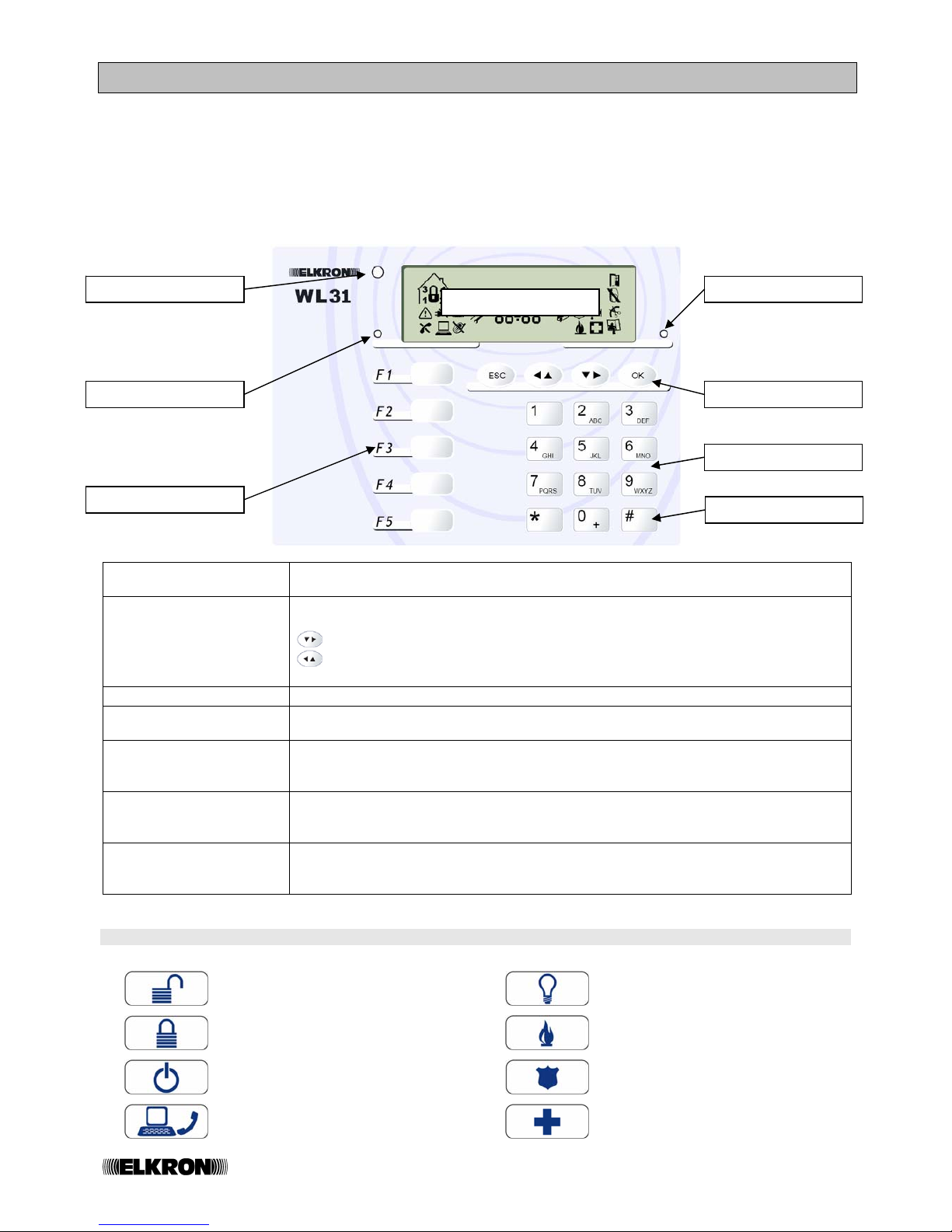
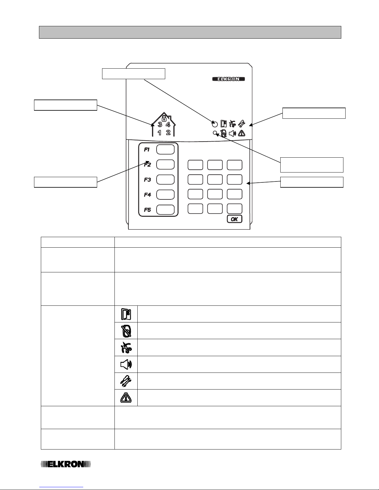
1.0 DESCRIPTION OF THE CENTRAL UNIT KEYBOARD
The keyboard is the interface between you and your protection system. Its main use is to control the total or partial
activation and deactivation of your alarm system, and to visualize its status on the display through a relating ICON.
A series of ICONS spontaneously turn on to signal the events that happen within the system. Some of the most
relevant events are the recording of an alarm, of a failure due to a dead battery or of an attempted sabotage on the
external siren.
Through the keyboard it is also possible to access a simple menu with “clear” messages, which will enable you to
carry out some simple operations.
Alphanumeric keys
These enable you to input characters and numbers and to access to the different
menu items.
Menu keys
These enable the surfing of the menu.
ESC: this goes up by one level in the menu tree.
this moves to the following menu item.
this goes back to the previous menu item.
OK: this moves to the sub-menu or confirm the displayed choice.
Failure presence LED
This signals the presence of damage in the system.
Alarm presence LED
This signals the presence of active events or the presence of alarm signalling in the
central unit memory.
Twilight sensor
This detects the level of environmental light and, if there is enough light, it excludes
the keyboard backlight. This is useful to reduce consumption and extend the
batteries’ life.
LCD Display
This shows using icons the system status, the programmed functions, the date and
the time.
It also shows the central unit messages during the system programming.
Function keys
These are programmable keys for a fast execution of the commands or alarms. It is
possible to personalize the keys with coloured labels, in order to make the choice of
the associated command more evident and comfortable.
1.1 FUNCTION KEYS PERSONALIZING LABELS
Deactivation
Service
Activation
Fire alarm
Toggle (status commutation)
Panic alarm
NOT USED
Emergency
LCD Display
Menu keys
Function keys
Failure presence LED
Alarm presence LED
Twilight sensor
Alphanumeric keys
MENU ACCESS key
6/32 WL31
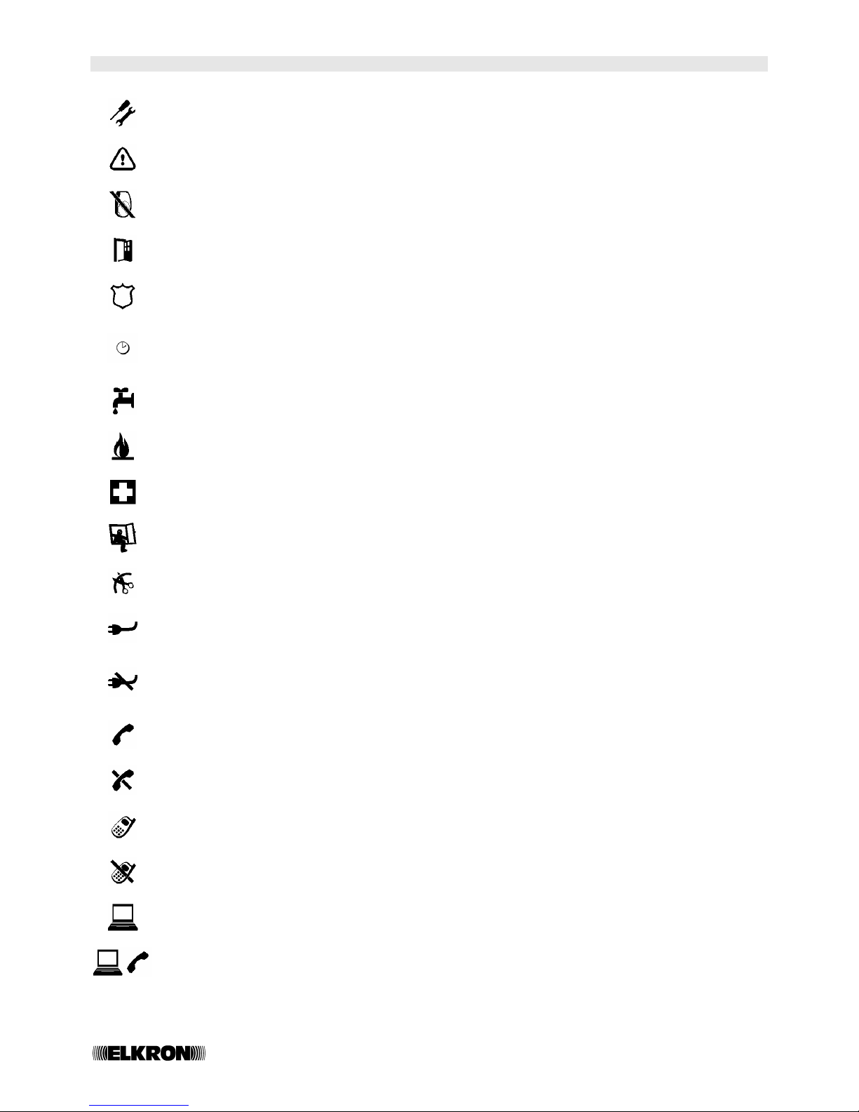
1.2 MEANING OF THE ICONS
SYSTEM UNDER MAINTENANCE SIGNALLING
This is on to signal access to the “Maintenance menu”. The Damage LED switches on.
FAILURE ALARM MEMORY
This is on to memorize a failure condition. The failure LED switches on.
INPUT EXCLUDED SIGNALLING
This is on to signal that a sensor has been excluded.
OPEN INPUT SIGNALLING
This is on to signal that a sensor is open (INPUT).
PANIC ALARM MEMORY
This is on to signal an alarm of the “panic with sirens” type. The Alarm’s LED switches on.
TIME CONTROL ENABLES SIGNALLING
This is on to signal that the automatic controls are enabled. It flashes during a control activation
warning time.
TECHNOLOGIC ALARM MEMORY
This is on to memorize an alarm of the “technologic” type. The Alarm LED switches on.
FIRE ALARM MEMORY
This is on to memorize an alarm of the “fire” type. The Alarm LED switches on.
EMERGENCY ALARM MEMORY
This is on to memorize an alarm of the “emergency” type. The Alarm LED switches on.
INTRUSION ALARM MEMORY
This is on to memorize an alarm of the “INTRUSION” type. The Alarm LED switches on.
DAMAGING ALARM MEMORY
This is on to memorize an alarm of the “damaging” type. The Alarm LED switches on.
ELECTRIC NETWORK PRESENCE SIGNALLING
This is always on in the presence of a PS30 power pack and of a 230Vac network.
NETWORK MISSING SIGNALLING or ALARM
This is on (if the PS30 power pack is present) to signal the absence of a 230Vac network. If the absence
exceeds the programmed time an alarm is generated (network missing) and the Damage LED switches
on.
PSTN TELEPHONE LINE PLUG SIGNALLING (WL31TG edition)
This is on to signal the use of the telephone line during tests.
MEMORY FOR PSTN TELEPHONE LINE MISSING ALARM (edition WL31TG)
This is on to signal and record the absence of the PSTN telephone line. The Damage LED switches
on
GSM PHONE LINE PLUG SIGNALLING (edition WL31TG and IMG30)
This is on to signal that the line is being used during a test.
MEMORY FOR GSM TELEPHONE LINE MISSING ALARM (edition WL31TG+IM30)
This is on to signal and record the absence of the GSM telephone line. The Damage LED switches on
CONNECTION TO LOCAL PC SIGNALLING
This is on to signal that the main board is connected with a PC.
REMOTE MANAGEMENT FROM PSTN LINE MEMORY (edition WL31TG)
This is on to record an in-coming call (on the PSTN line) for a MODEM connection (Fast Link).
7/32 WL31
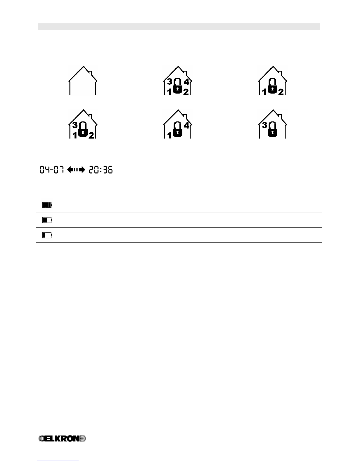
1.3 INFORMATION ON THE SYSTEM’S STATUS
The following indications are permanently shown on the display
1.3.1 SYSTEM’S STATUS (FOR EXAMPLE REFERRING TO A SYSTEM WITH FOUR SECTORS)
DEACTIVATED SYSTEM TOTALLY ACTIVE SYSTEM SECTORS 1 AND 2 ACTIVE
SECTORS 1, 2, 3 ACTIVE SECTORS 1 AND 4 ACTIVE SECTOR 3 ACTIVE
DATE / TIME
These are alternatively shown on the display
1.3.2 BATTERIES’ STATUS
OK BATTERY SIGNALLING - Always on. It shows the status of the batteries of the whole system.
LOW BATTERY SIGNALLING - One or more of the system’s batteries have gone under 30% of their charge.
DEAD BATTERY ALARM - One or more system’s batteries are dead (to be replaced within one month).
The failure LED switches on.
1.3.3 HOW TO DISPLAY A SIGNAL IN DETAIL
In order to display a signal in detail (when the system is deactivated), do as follows:
- Press the OK key: the first (from right to left) icon on the display flashes and the type of signal is shown in a
lighter colour.
Using the arrow keys it is possible to display the other existing icons (events), or, by pressing the OK key, it is
possible to display the list of the devices that generated a signal.
1.3.4 HOW TO DISPLAY AN ALARM MEMORY IN DETAIL
In order to display an alarm memory in detail, do as follows:
- Press the OK key: the first (from right to left) icon on the display flashes and the type of signal will be
shown in a lighter colour.
Using the arrow keys it is possible to display the other existing icons (alarm memories), or, by pressing the OK key,
it is possible to display the list of the devices that generated a signal. At the end of the visualization, if the event is
not present anymore, the icon will be cancelled (memory reset). The icons which memorize events which depend
on the system’s status will be automatically cancelled at the next activation.
8/32 WL31
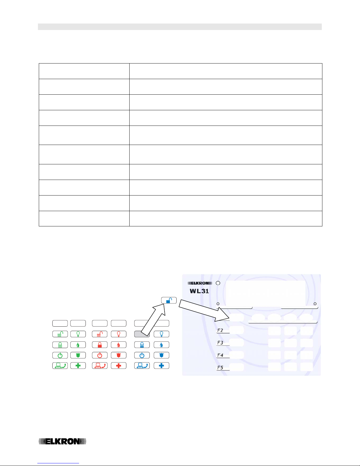
1.4 FUNCTION KEYS PROGRAMMING
Your technician can program a specific function for each of the 5 function keys.
The following list shows the functions which can be allocated to the function keys.
TOTAL ACTIVATION
This completely activates the system
TOTAL DEACTIVATION
This completely deactivates the system
SECTOR/S ACTIVATION
This activates one or more of the system’s sectors (partial activation)
SECTOR/S DEACTIVATION
This deactivates one or more of the system’s sectors (partial activation)
TOTAL
ACTIVATION/DEACTIVATION
(SYSTEM TOGGLE)
This activates/deactivates the system totally
SECTOR
ACTIVATION/DEACTIVATION
(SECTORS TOGGLE)
This activates/deactivates one or more sectors (partial activation/
deactivation)
SIREN PANIC ALARM
This activates the system sirens (the sound is automatically interrupted after
the programmed time)
SILENT PANIC ALARM
The telephone transmittor sends a telephone call to the programmed
number (WL31TG only)
EMERGENCY ALARM
The telephone transmittor sends a telephone call to the programmed
number (WL31TG only)
SERVICE COMMAND
Using this command it is possible to manage, for example, the opening of
an automatic gate or the opening of a horizontally pivoted garage door
The five function keys (F1…F5) can be personalized using the specific labels which should be positioned under the
supplied transparent keys cover.
9/32 WL31
2.0 DESCRIPTION OF THE REMOTE KEYBOARD
The remote keyboard carries out similar functions to the main one. Its main use is to control the total or partial
activation and deactivation of your alarm system, displaying its status through a series of LEDs.
1
2
3
4
5
6
7
8
9
*
0
#
Alphanumeric keys
These enable you to input the secret code required to access the system’s functions.
Function keys
These have been programmed for fast commands or alarm executions. It is possible
to personalize these keys with coloured labels, in order to make the choice of the
associated control more evident and comfortable.
Generic signalling LED
(recapitulation)
This is on in a GREEN colour when information is being transmitted/received from
the central unit;
This is on in a RED colour when alarms and failures are being recorded.
Blinking GREEN = communication running
OPEN INPUT SIGNALLING
This is on to signal that a perimeter detector is open.
INPUT EXCLUDED SIGNALLING
This is on to signal that a detector has been excluded.
INTERFERENCE ALARM MEMORY
This is on to memorize an alarm of the “interference” type.
ALARMS MEMORY
This is on to memorize an alarm.
SYSTEM IN MAINTENACE SIGNALLING
This is on to signal the access to the “Maintenance” menu.
Specific signalling
LEDs
FAILURE ALARM MEMORY
This is on to memorize a failure condition.
Twilight sensor
This detects the level of environmental light and, if there is enough light, it excludes
the keyboard backlight. This is useful to reduce consumption and extend the
batteries’ life.
System Status LEDs
These show the system status.
LED on in a GREEN colour = DEACTIVATED SECTOR
LED on in a RED colour = ACTIVATED SECTOR
Function keys
Generic signalling LED
(recapitulation)
Twilight sensor
Alphanumeric keys
System status LED
Specific signalling LED
10/32 WL31
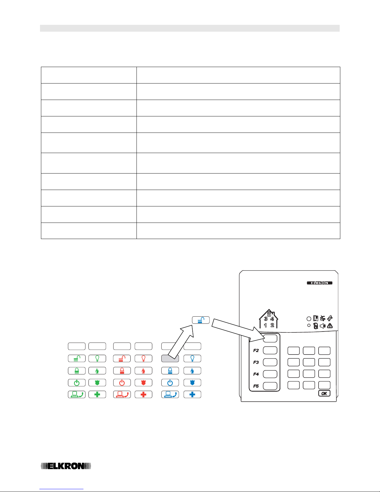
2.1 PROGRAMMABILITY OF THE REMOTE KEYBOARD FUNCTION KEYS
Your technician can program a specific function for each of the 5 function keys.
The following list shows the functions which can be allocated to the function keys.
TOTAL ACTIVATION
This completely activates the system
TOTAL DEACTIVATION
This completely deactivates the system
SECTOR/S ACTIVATION
This activates one or more of the system’s sectors (partial activation)
SECTOR/S DEACTIVATION
This deactivates one or more of the system’s sectors (partial activation)
TOTAL
ACTIVATION/DEACTIVATION
(SYSTEM TOGGLE)
This activates/deactivates the system totally
SECTOR
ACTIVATION/DEACTIVATION
(SECTORS TOGGLE)
This activates/deactivates one or more sectors (partial
activation/deactivation)
SIREN PANIC ALARM
This activates the system sirens (the sound is automatically interrupted after
the programmed time)
SILENT PANIC ALARM
The telephone transmittor sends a telephone call to the programmed
number (WL31TG only)
EMERGENCY ALARM
The telephone transmittor sends a telephone call to the programmed
number (WL31TG only)
SERVICE COMMAND
Using this command it is possible to manage, for example, the opening of
an automatic gate or the opening of a horizontally pivoted garage door.
The five function keys (F1…F5) can be personalized using the specific labels to be positioned under the supplied
transparent keys cover.
1
2
3
4
5
6
7
8
9
*
0
#
 Loading...