

DS80SC61-001C LBT80096
User’s manual
GB
FAP54
Multiprocessor
modular control panel
for fire detection

2 FAP User
The information contained in this document has be en collected and controlled carefully. However, the company cannot be he ld
responsible for any possible errors and omissions.
The company reserves the right to make, at any time and without warning, improvements and modifications to the products
described in this manual.
In this manual, you may find references and information about products (hard ware or software) or services not commer cialized yet.
These references and information do not imply that the company intends to commercialize these products and services.
Elkron is a trademark of URMET S.p.A.
All trademarks mentioned in this document belong to the corresponding owners.
All rights reserved. The total or partial reproduction of this document is authorised only for installation purposes of the FAP54
System.
Tel. +39 011.3986711 – Fax +39 011.3986703
www.elkron.com – mail to: Hinfo@elkron.it

FAP User 3
TABLE OF CONTENTS
TABLE OF CONTENTS...................................................................................................................................................................... 3
1 OPERATING MODES.................................................................................................................................................................. 4
2 SCANNING PHASE..................................................................................................................................................................... 4
3 ALARM DISPLAY........................................................................................................................................................................ 5
4 GENERAL FAULT DISPLAY ....................................................................................................................................................... 6
5 FIELD FAULT DISPLAY.............................................................................................................................................................. 6
6 EXCLUSION DISPLAY................................................................................................................................................................ 7
7 MAINTENANCE DISPLAY........................................................................................................................................................... 8
8 SLAVE CONTROL PANEL DISPLAY ......................................................................................................................................... 9
9 GENERIC EVENTS DISPLAY ................................................................................................................................................... 10
10 CONTROL PANEL FUNCTIONAL STATES ...................................................................................................................... 10
11 FIRST LEVEL OPERATIONS............................................................................................................................................. 11
12 INCLUDE/EXCLUDE PUSHBUTTON................................................................................................................................. 12
13 KEYS AND INDICATORS FOR THE OPERATOR............................................................................................................. 13
14 FAP54-01 KEYPAD LAYOUT.............................................................................................................................................15
15 FAP54-04/08/16 KEYPAD LAYOUT................................................................................................................................... 16
16 OPERATIONS TO BE CARRIED OUT IN CASE OF ALARM............................................................................................ 17
17 OPERATIONS TO BE CARRIED OUT IN CASE OF FAULT............................................................................................. 17
18 APPENDIX.......................................................................................................................................................................... 18
18.1 APPENDIX 1 – ERROR CODES FOR FAULT OF POINTS........................................................................................... 18
18.2 APPENDIX 2 – FAULT CODES FOR LINE CIRCUIT CARDS....................................................................................... 20
18.3 APPENDIX 3 – FAULT CODES FOR THE COMMAND AND CONTROL MODULE...................................................... 20
18.4 APPENDIX 4 – FAULT CODES FOR THE LCD ANNUNCIATORS...............................................................................21
18.5 APPENDIX 5 – FAULT CODES FOR MODEM .............................................................................................................. 21
18.6 APPENDIX 6 – SYSTEM ERROR CODES .................................................................................................................... 22
18.7 APPENDIX 7 – FAULT CODES FOR SLAVE CONTROL PANELS...............................................................................23
18.8 APPENDIX 8 – LIST OF PC SUBCOMMANDS (CMD “EXECUTE ACTION”) ............................................................... 23
18.9 APPENDIX 9 – POINT TYPES....................................................................................................................................... 24
18.10 APPENDIX 10 – POINT ATTRIBUTES QUALIFIER....................................................................................................... 24
18.11 APPENDIX 11 – ALARM TYPES.................................................................................................................................... 24
18.12 APPENDIX 12 – ZONE TYPES...................................................................................................................................... 25
18.13 APPENDIX 13 – ERROR CODES FOR PRINTER MODULE......................................................................................... 25
18.14 APPENDIX 14 – PS2 KEYBOARD MAPPING................................................................................................................ 25
18.15 APPENDIX 15 – ERROR CODES FOR CIRCUIT FAULT (COMMUNICATION ERROR) ............................................. 26

4 FAP User
1 OPERATING MODES
The FAP54 control panel has two operating modes: scanning phase and programming phase.
When FAP54 is powered on, the scanning phase will be always started and maintained until the installer or the user
carries out an intervention.
2 SCANNING PHASE
In this operating mode the control panel monitors the detectors scattered in the field and manages the following
events:
alarm
general fault
field fault
maintenance
exclusion
events related to slave control panels (if the control panel is set as master)
generic events (not classified into any of the previous categories)
Normally, if there are not active events, the display on the control panel front side shows the following message:
The event indicator is shown when at least one event has occurred since the last time a level 2 password has been
inserted. If no event has occurred, a blinking asterisk will be displayed instead of the event indicator.
If the control panel has not been programmed yet, the display shows the message “MONITORING NOT POSSIBLE”.
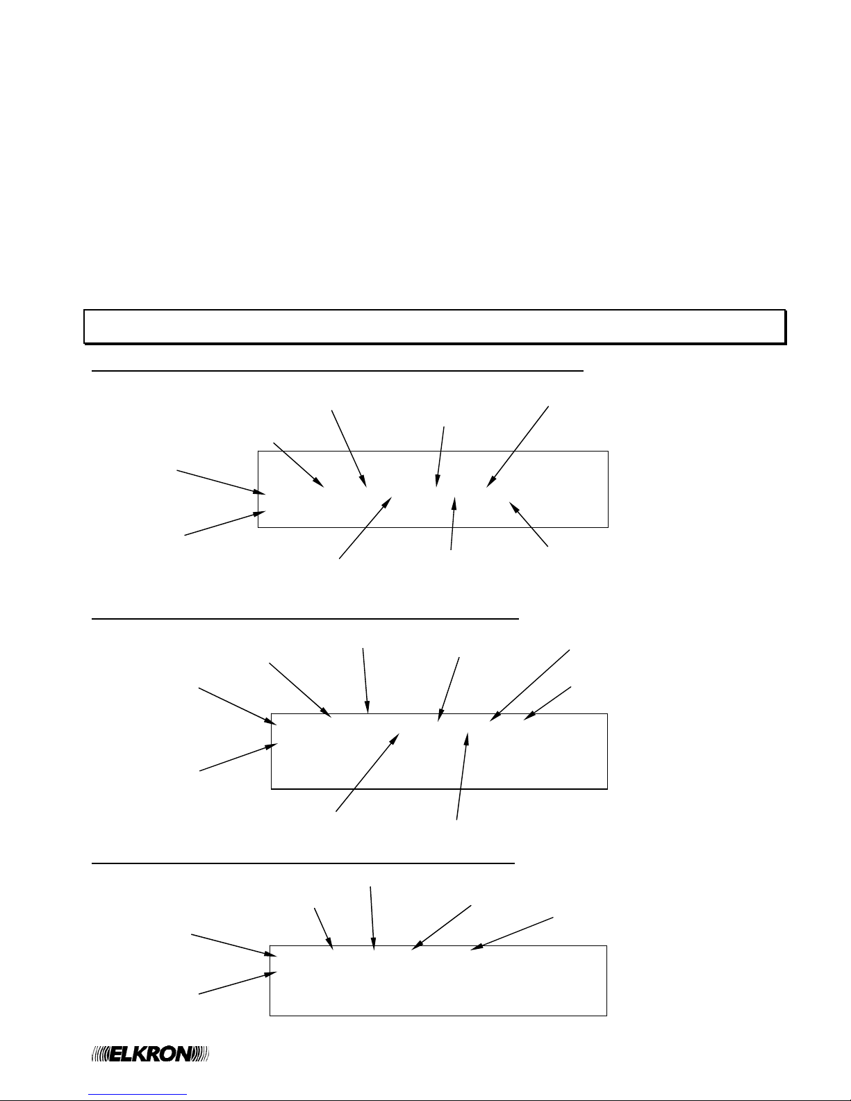
If an event occurs, the display shows the event, along with the cumulative counters for each type of event on the righthand side.
Should more events occur, the display shows, in addition to the event counter increase, the first event occurred at the
top and the most recent alarm (if present) at the bottom.
ALM Z002 R00 L01 D015 SM A101 >ZA003
KITCHEN DETECTOR GF000
ALM Z110 R00 L01 D018 SM A101 FF000
CORRIDOR DETECTOR EX000
Event cumulative
counters
First event
occurred
Last alarm
occurred
Time
#
FIRE DETECTION SYSTEM
12/10/2008 11:50:42
FAP54-04
Date
Type of Control panel
System name
Event indicator
FAP User 5
The events are displayed according to the following priority:
• Zones in alarms (ZA)
• General faults (GF)
• Field faults (FF)
• Exclusion (EX)
• Group of points in alarm (GP)
• Group of zones in alarm (GZ)
• Maintenance (MN)
• Events related to SLAVE control panels (SP)
• Generic events (GE)
By using the keys ∧ and ∨ it is possible to change the type of event displayed (the > symbol on the right selects
the type of the event currently shown on the first two rows).
By using the keys < and > it is possible to go back and forth through the events of the selected type.
The selected event will be displayed at the top, while the most recent alarm event will be displayed at the bottom (if at
least one alarm is present) or nothing will be displayed.
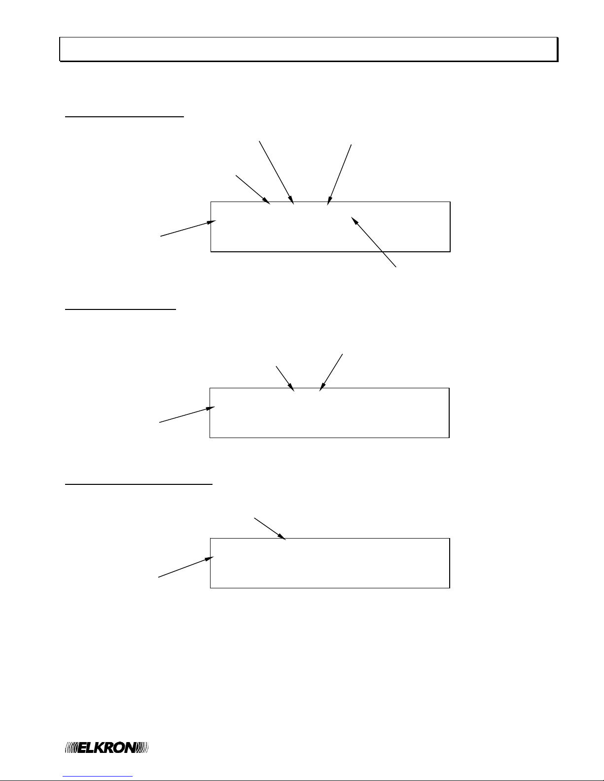
3 ALARM DISPLAY
Display of Zone Alarm generated by detector/pushbutton associated with zone
Display of alarm of group of points generated by an associated point
Display of alarm of group of zones generated by an associated zone
>ZA001
GF000
ALM Z110 D00 C01 P018 TP Q Axyy FF000
KITCHEN DETECTOR EX000
Zone delay
Point name
Alarm event indicator
No. of zone in alarm
Circuit of the point in alarm
Point type
(see appendix)
Point address
Point attributes
(see appendix)
Ax = service information
yy = alarm type (see appendix)
ALM G020 D00 C01 P018 TP Q Ax >GP001
KITCHEN DETECTOR GZ000
MN000
SP000
Point name
Alarm event indicator
Group number
Group delay
Circuit of the point in alarm
Point type (see appendix)
Point address
Point attributes
(see appendix)
Service information
ALM G025 D00 Z033 Ax GP000
BOILER ROOM >GZ001
MN000
SP000
Zone name
Alarm event indicator
Group number
Group delay
Zone in alarm
Service information

6 FAP User
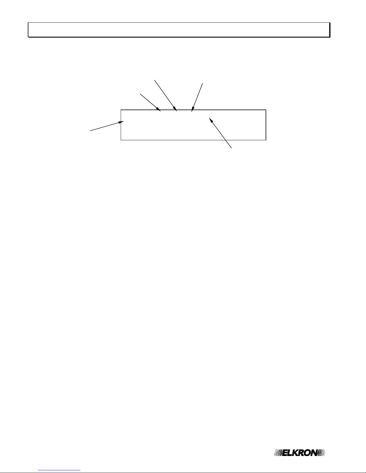
4 GENERAL FAULT DISPLAY
The display of a general fault depends on the type of event occurred and it usually allows the immediate recognition of
the equipment or part of the control panel in faulty condition which can negatively affect the system operation.
In any case, the display shows each event with all the data needed for the equipment identification (e.g. address) and
the related error code.
Example:
Note that some type of fault is notified with a self explaining message, allowing the user to immediately understand
what is going on. Other types of fault are notified instead with a message and an error code. For a detailed
explanation of these codes, please refer to the appendixes.
5 FIELD FAULT DISPLAY
The display of a field fault depends on the type of fault.
Usually, a field fault affects a detection circuit or a device connected to this circuit.
A field fault due to a device is notified as follows:
The field fault can affect also the detection circuit and occur, for instance, because of a short circuit or when the circuit
is configured in loop mode and the loop breaks.
In any case, a self-explaining message will be displayed. Below is reported an example of a field fault of type “short
circuit” affecting circuit 1.
Panel name
FAULT REMOTE PANEL 05 (01) ZA000
PANEL NAME >GF001
FF000
EX000
Type of fault
Address of faulty panel
Fault code
FAULT Z020 C01 P018 TP Q F001 ZA000
KITCHEN DETECTOR GF000
>FF001
EX000
Point name
Zone which the point belongs to
Faulty point address
Point type
(See appendix)
Circuit of faulty point
Fault type
Point attributes
(see appendix)
FAULT CIRCUIT 01 ZA000
SHORT CIRCUIT GF000
>FF001
EX000
Type of fault
No. of faulty circuit
FAP User 7
6 EXCLUSION DISPLAY
During the scanning phase it is possible to know the state of the active exclusions regarding the equipment
connected with the control panel, the abstract entities (zones, groups), the devices and the detection lines.
A few examples are reported below.
Display of excluded device
Display of excluded zone
Display of excluded remote panel
EXCL. Z020 C01 P018 SM ZA000
KITCHEN DETECTOR GF000
FF000
>EX001
Point name
Zone which the point belongs to
Address of excluded point
Point type
Circuit of excluded point
EXCL. ZONE 020 FR ZA000
FIRST FLOOR GF000
FF000
>EX001
Zone name
excluded zone number
Zone type (see appendix)
EXCL. REMOTE PANEL 05 ZA000
PANEL NAME GF000
FF000
>EX001
Panel name
Type of exclusion
8 FAP User
7 MAINTENANCE DISPLAY
The display of a device requiring maintenance allows the immediate recognition of a smoke detector which needs to
be replaced or cleaned as it is no longer reliable. Therefore, the display will show the information necessary to identify
the device on the circuit.
MAINT. Z020 C01 P018 SM GP000
KITCHEN DETECTOR GZ000
>MN001
SP000
Detector name
Relevant zone
Address of detector
under maintenance
Type of detector
Circuit of detector
under maintenance

FAP User 9
MAINT. Z020 C01 P018 SM GP000
KITCHEN SMOKE DETECTOR GZ000
>MN001
SP000
SLAVE 050 HANGAR GP000
MAINT. Z020 C01 P018 SM GZ000
MN000
>SP001
SLAVE 050 HANGAR GP000
ACTIVE EXCLUSIONS 007 GZ000
MN000
>SP001
8 SLAVE CONTROL PANEL DISPLAY
This section is valid only if the control panel is configured as a MASTER and it is connected to a network of SLAVE
control panels.
Any event occurring on a SLAVE control panel is notified to the MASTER control panel, which shows it by using two
rows, according to the following rules:
• the first row shows the address and name of the SLAVE control panel affected by the event,
• the second row equals the first row used by the SLAVE control panel to show the event on its own display
For instance, suppose that the SLAVE control panel with address 50 and named “HANGAR” is affected by a
maintenance event on a smoke detector.
This SLAVE control panel, then, shows the following message on its display:
The MASTER control panel to whom the SLAVE control panel is connected shows the following information:
This message says to the user that the smoke detector, located on circuit 1 in the SLAVE 50 and having the address
18, requests a maintenance intervention.
Moreover, it says that the SLAVE control panel with address 50 is also named “HANGAR”.
Alarms, faults and maintenance events occurring on a SLAVE control panel are displayed on the MASTER control
panel’s display according to the aforementioned rule (address and name of the SLAVE control panel plus the first row
of the event shown in the SLAVE control panel).
The events of exclusion/inclusion occurring on a SLAVE control panel are handled in a differe nt way.
If a SLAVE control panel is affected by at least one exclusion, the MASTER control panel shows a message like this:
This message indicates the number of elements currently excluded on the SLAVE control panel (in the example,
there are 7 active exclusions on the SLAVE control panel).
If all the currently excluded elements are re-included, the above message is not shown anymore.
In the case the user wants to receive further information on the events occurring in the SLAVE control panel (for
instance, the name of the point requiring maintenance, or detailed information on the excluded elements), it is
necessary to get to the event log of the SLAVE control panel.
The event log of the SLAVE control panel can be accessed directly from the MASTER control panel’s display. In order
to do this, it is necessary to view any event of the SLAVE control panel of interest in the MASTER control panel’s
display and then press OK.
By pressing OK again when the log of the SLAVE panel is shown in the MASTER panel’s screen, a menu (protected
by level 2 password) is shown which allows the MASTER to send commands (e.g. GLOBAL RESET,
ACKNOWLEDGEMENT, SILENCE/REARM SIREN, etc.) to the SLAVE panel.
For further information on this topic, please refer to the programming manual.

10 FAP User
EVENT NOT AVAILABLE GD000
GZ000
MN000
>SP000
NOTE - consider the following condition:
• the panel is a MASTER and it is connected to one or more SLAVE panels
• the MASTER contains local events ( (there are folders other than SP which are not empty)
• the SP folder is not empty and the events are all generated by the same SLAVE panel
• the MASTER is currently showing events from the SP folder
Under the aforementioned conditions, if the SLAVE panel undergoes a GLOBAL RESET the MASTER switches
temporarily to the following screen:
After 20 seconds, the MASTER shows the events of the first not empty local folder.
9 GENERIC EVENTS DISPLAY
The folder of generic events is suited for events which must be displayed but cannot be classified in any of the
previous categories.
They are:
Events of block/resume of actuations for output modules
Events related to modem connections (incoming calls, outgoing calls for alarms/faults/maintenance)
10 CONTROL PANEL FUNCTIONAL STATES
NORMAL: all the indicators are normally OFF but the following LEDs:
AC: steady green if the control panel is powered on by the main power, blinking green if the control panel is
powered on by batteries
LEDs of the “EXCLUSIONS” group, if there are active exclusions
TEST SYSTEM if there is a system test in progress
ALARM: when an alarm occurs, the control panel switches to the ALARM state and the following statements are true:
• the FIRE ALARM LED (located on the topmost left side of the panel) starts blinking (if the siren output is not
activated) or is steady ON (if the siren output is activated);
• the ALARM relay is activated
• if the siren output is activated, the SIREN relay is activated as well
• all the actuator modules are activated (if properly programmed) according to the alarm level reached by the
panel (alarm 1 = alarm with siren output OFF, alarm 2 = alarm with siren output ON)
• the control panel starts emitting a continuous whistle and the display notifies the user about the alarmed
device/s.
FAULT: in the case of fault, the control panel will emit an intermitting whistle; moreover, the yellow LED of the
General Fault indicator plus another LED related to specific faults (e.g. System, Battery, Siren and Ground
Dispersion) will be turned ON. The display will notify the user about the fault.
To stop the whistle press ACK.
Once the fault has been solved press RESET.

FAP User 11
11 FIRST LEVEL OPERATIONS
ACK: by pressing ACK the control panel buzzer will be silenced and the event displayed will be acknowledged.
ALARM SILENCING: by pressing SILENCE / RESTART SIREN the active device (plates or sirens) sound will be
temporarily stopped. The yellow LED associated with the SILENCED SIREN will turn on.
To restore the sound, press again the SILENCE / RESTART SIREN.
The yellow LED associated with SILENCED SIREN will turn off.
RESET: press RESET to restore the control panel normal operation. All the indicators (LEDs, displays) will be
disabled and all the related functions restored.
DISPLAY DESCRIPTION: the control panel display is composed of 4 lines. The first two lines indicate initially the first
alarm or the last non alarm event occurred, whereas the other two lines show the last alarm occurred (if any alarm
exists).
In order to move back and forth on the list of events belonging to the currently selected category, press the buttons <
and >. The currently selected event will be shown on the first two rows of the display.
The currently selected category is the one correspondent to the position of the event type selector > on the right-hand
side of the screen.
In order to change the event category operate on the buttons ∧ and ∨ .
The counters referring to the type of events, located on the right-hand side of the display, are:
ZA
(Zones in alarm): number of zones in alarm
GF
(General Fault): number of general faults
FF
(Field Fault): number of field faults
EX
(Exclusion):
number of exclusions in progress without distinguishing among circuits,
zones, groups or devices
GP
(Group of points in alarm): number of groups of points in alarm
GZ
(Group of zones in alarm): number of groups of zones in alarm
MN
(Maintenance): number of devices requiring maintenance
SP
(Slave control panel events):
number of alarm events + field fault events + general fault events +
maintenance events occurred on the slave control panels
GE
(Generic events):
number of generic events (block/resume actuations and modem
connections)

12 FAP User
[1] INCLUDE/EXCLUDE CIRCUIT
[2] INCLUDE/EXCLUDE POINTS/ZONES
[3] INCLUDE/EXCLUDE PERIPHERALS
[4] INCLUDE/EXCLUDE OUTPUTS
[1] INCLUDE/EXCLUDE POINTS
[2] INCLUDE/EXCLUDE ZONES
[3] INCLUDE/EXCLUDE GROUPS OF POINTS
[4] INCLUDE/EXCLUDE GROUPS OF ZONES
[1] INCLUDE/EXCLUDE PRINTER
[2] INCLUDE/EXCLUDE MODEM
[3] INCLUDE/EXCLUDE LCD ANNUNCIATORS
[4] INCLUDE/EXCLUDE SLAVE PANELS
[1] INCLUDE/EXCLUDE SIREN OUTPUT
[2] INCLUDE/EXCLUDE SIREN RELAY
[3] INCLUDE/EXCLUDE AC/EXCL. RELAY
[4] INCLUDE/EXCLUDE FAULT RELAY
12 INCLUDE/EXCLUDE PUSHBUTTON
When the control panel is monitoring the field it is possible to include or exclude circuits, zones, groups, points,
functions or equipment connected to the control panel without switching over to the programming phase.
The access to this menu requires the level 2 password, if enabled.
By pressing INCLUDE/EXCLUDE, the following menu will be displayed:
By selecting 2, the following menu will be displayed:
By selecting 3, the following menu will be displayed:
The item related to inclusion and exclusion of SLAVE control panels is only shown if the control panel is configured as
MASTER.
By selecting 4, the following menu will be displayed:
After selecting the required option, the inclusion or exclusion operation will be carried out in the same way and with
the same menus used during programming.
Please, refer to the Programming manual for further information.
NOTE: if a circuit is included or excluded, the relevant detection line will be powered off in the case of exclusion and
powered on as soon as the circuit is included again.
The power-on of the line could last long (even a few minutes) and during this time the control panel does NOT carry
out any monitoring of the field. Therefore, possible alarms occurring on other lines during this time will not be
detected.
In order to prevent any problems due to alarms detected by a detector/module and not promptly accepted by the
control panel, the inclusion/exclusion menu is considered a shortcut for the corresponding programming me nu.
Therefore, the password needed to access this menu is the one required to access the programming menu (level 3
password). As a result, if the passwords are enabled and the user previously entered a password of a lower level, the
suitable password will be requested.

FAP User 13
13 KEYS AND INDICATORS FOR THE OPERATOR
KEY FUNCTION
ACK
( )
This key must be pressed to acknowledge the events (alarms, faults,
maintenance) detected by the control panel.
RESET
This key starts the “Global Reset” procedure.
Whenever the user presses this key, an event is stored in the event log and, if
the passwords are enabled, the level 2 password is required.
SILENCE /
REARM SIREN
This key stops and restarts the siren output and the alarm outputs of the actuators after
the occurrence of an alarm. Whenever the user presses this key, an event is stored in the
event log and, if the passwords are enabled, the level 2 password is required.
SKIP DELAY
This key makes the siren output activation delay expire immediately when the
control panel is in alarm condition of a zone/group alarm in timer mode and the
timer is running.
By pressing this key the control panel will ignore the delay and will
activate the siren output immediately.
INCREASE DELAY
In order for this key to have an effect, the timer of a zone/group alarm in time
mode must be running. In this situation, when this key is pressed the current
value of the running timer is increased by 1 minute. The maximum overall time
(initial delay + increments due to the key) is 10 minutes. Whenever the user
presses this key, an event is stored in the event log and, if the passwords are
enabled, the level 2 password is required.
MASTER ALARM
When the control panel is in monitoring phase, this key triggers the general alarm
condition. Whenever the user presses this key, an event is stored in the event
log and, if the passwords are enabled, the level 2 password is required.
INCLUDE/EXCLUDE
When the control panel is in monitoring phase, this key allows the user to
include/exclude circuits, zones, groups, points or any other equipment connected
to the control panel. When the user presses this key, the level 2 password is
required (if passwords are enabled).

14 FAP User
INDICATOR COLOR FUNCTION
FIRE ALARM RED
Blinking: the control panel is in alarm condition and the siren
output is not active
Fixed ON: the control panel is in alarm condition and the siren
output is active
ALARMS
MASTER ALARM RED When turned ON, a general alarm condition has occurred
MODEM ACTIVE
RED
Blinking: the modem is attempting to setup a call
Steady ON: the modem connection is active
Steady OFF: the modem is not performing any activity
MODEM
MODEM STATE YELLOW
Blinking: fault on the transmission line
Fixed ON: modem (or part of its functionality) excluded
GENERAL YELLOW
When turned ON, it indicates a Fault condition. Further information on
the type of fault is provided through the display and the dedicated
LEDs. This LED provides a cumulative fault indication
SYSTEM YELLOW
When turned ON, it indicates a system fault. Usually, when this LED
is ON it indicates a fault affecting the CPU of the control panel.
BATTERY YELLOW When ON, it indicates a control panel battery fault or malfunctioning.
SIREN YELLOW
When ON, it indicates a fault on the line controlling the sire n or a fa ult
on an actuator driving an alarm signalling device (“C” type)
FAULTS
EARTH YELLOW When ON, it signals an earth dispersion
MAINTENANCE YELLOW
When ON, it indicates that the maintenance procedure has found on e
or more smoke detectors which require maintenance.
MAINTENANCE
TEST SYSTEM YELLOW When ON, it indicates that a zone test is in progress.
MAIN/BATTERY GREEN
Steady ON: the control panel is powered on by the main AC
Blinking: the control panel is powered on by batteries
LINE YELLOW When ON, it indicates that one or more circuits are excluded.
ZONE YELLOW When ON, it indicates that one or more zones are excluded.
GROUP YELLOW
When ON, it indicates that one or more groups of points or groups of
zones are excluded.
DEVICE YELLOW When ON, it indicates that one or more points are excluded.
SIREN YELLOW
When ON, it indicates the exclusion of a siren or an actua tor driving
an alarm signaling device (“C” type).
EXCLUSIONS
DISCHARGE YELLOW
When ON, it indicates the exclusion of an actuator driving fireextinction equipment (“G” type).
EXCLUSION YELLOW
When ON, it indicates that something is excluded in the control panel.
This is an exclusion cumulative indicator.
REMOTE DEVICE YELLOW
When ON, it indicates a communication error during communication
with an LCD annunciator or a SLAVE control panel, or a
communication problem during communication with a PC via modem
or LAN.
SILENCE SIREN YELLOW
When ON, it indicates that the siren output has been turned off by
using the SILENCE SIREN key.
GENERAL
ACTION DELAYED YELLOW
When ON, it indicates that the timer of a zone or group in time mode
is running or has expired and the zone or g roup has undergone an
alarm condition.

FAP User 15
14 FAP54-01 KEYPAD LAYOUT

16 FAP User
15 FAP54-04/08/16 KEYPAD LAYOUT

FAP User 17
16 OPERATIONS TO BE CARRIED OUT IN CASE OF ALARM
1. Press ACK.
2. Read the point in alarm on the display.
3. Go and check the possible alarm on the field. If no problems are detected or no real danger exists press
RESET.
Should the alarm persist it is possible to exclude the point as follows:
1. Press ACK.
2. Read the point in alarm on the display.
3. Press INCLUDE/EXCLUDE.
4. Select the option INCLUDE/EXCLUDE POINTS/ZONES
5. Select the option INCLUDE/EXCLUDE POINTS
6. Select the circuit where the point to be excluded is located by operating ∧ and ∨
7. Press OK
8. Select the point to be excluded by entering the address or using keys ∧ and ∨ or typing in the address on the
numerical keypad
9. Press OK
10. Select EXCLUDED through ∧ and ∨
11. Press OK
12. Press ESC until a message indicating the excluded point is displayed
13. Press RESET.
To include a previously excluded point proceed as follows:
1. Press INCLUDE/EXCLUDE.
2. Select the option INCLUDE/EXCLUDE POINTS/ZONES
3. Select the option INCLUDE/EXCLUDE POINTS
4. Select the circuit where the point to be included is located by operating ∧ and ∨
5. Press OK
6. Select the point to be included by entering the address or using keys ∧ and ∨ or typing in the address on the
numerical keypad
7. Press OK
8. Select INCLUDED through ∧ and ∨
9. Press OK
10. Press ESC
until the control panel goes back to the messages shown during the scanning phase and the
message related to the excluded point is not shown anymore
11. Press RESET.
17 OPERATIONS TO BE CARRIED OUT IN CASE OF FAULT
1. Press ACK.
2. Read the cause of fault on the display.
3. Go and check the possible fault on the spot. If no problems are detected or no real danger exists press
RESET.
4. Should the fault persist press ACK and contact service.

18 FAP User
18 APPENDIX
18.1 APPENDIX 1 – ERROR CODES FOR FAULT OF POINTS
If a point undergoes a fault, this fault is detected by the control panel during the scanning phase and the user is
notified about it with a message:
FAULT ZXXX CYY PZZZ TT FWWW
NAME OF THE POINT
XXX = number of the zone which the point belongs to
YY = circuit which the point is connected to
ZZZ = address of the point
TT = type (in short) of the point
WWW = fault code
If the point is an output module, the user is notified about the fault with one of the following messages, depending on
the fault:
FAULT EXT. CXX PYYY OM FZZZ
NAME OF THE MODULE
or:
FAULT CXX PYYY OM FZZZ
NAME OF THE MODULE
XX = circuit which the module is connected to
YYY = address of the module
ZZZ = fault code

FAP User 19
The following table contains the point error codes and the relevant explanation.
Code Fault
1 Smoke/heat detector: internal fault of the optical section
2 Smoke/heat detector: internal fault of the optical section (signal less than the fault threshold)
3 Internal fault of the temperature detection section
4 Smoke detector: error at the end of the optical calibration procedure
5 Smoke detector: optical calibration is missing because of out of range temperature
6 Internal fault: non volatile memory access error
7 Internal fault: testing not executed
8 Internal fault: optical calibration not executed
9 Internal fault: calibration failed
10 Heat detector or smoke/heat detector: internal fault of the temperature detection section.
11 Manual push button: internal fault of the alarm switch
12 External fault: analog input 1 is short circuited
13 External fault: analog input 1 is open (end of line resistor is missing)
14 External fault; analog input 2 is short circuited
15 External fault: analog input 2 is open (end of line resistor is missing)
16
External fault: missing short circuit of input 1 of a mode 2 actuator within the expected time
(feedback time)
17 External fault: alarm repetition output is short circuited
18
The point has notified an external fault, but it is not possible to read the cause because of a
communication problem
19 Type programming error
20 The point does not answer to the cyclic polling during the monitoring phase
21 The point does not answer to a command
22 The point does not answer to the initial polling at the beginning of the monitoring phase
23
The point answers wrongly with a too high current to the polling during the monitoring phase
(possible answer coming simultaneously from more than one point)
24 The point type is different than the programmed one
25 Point not accepted because of wrong manufacturer code
26 The point does not answer to the adaptation command
27 The point does not answer to the status request command for inclusion verification
28 The point does not answer to the command of inclusion
30 External fault: alarm repetition/siren output is open (end of line resistor is missing)
31 External fault: alarm repetition/siren output is short circuited
32 External fault: electrical overloaded on the gemma output
33 External fault: external power supply applied to a point programmed to work without it
34 External fault: external power supply missing on a point programmed to work with it
35
External fault: the value read is lower than the threshold of fault of the analog section (possible
break of the electric connection with the measurement equipment)
36 External fault: conventional detection circuit is short circuited
37 External fault: conventional detection circuit is open (end of line resistor is missing)
38 Dip-switch configuration on the device is different than the one programmed in the control panel
40 -43
Failure of the attempt to recovery communication with the point after a missing answer to the
cyclic polling during the monitoring phase

20 FAP User
18.2 APPENDIX 2 – FAULT CODES FOR LINE CIRCUIT CARDS
If a circuit module undergoes a fault during the scanning phase, the control panel detects this fault and notifies the
user with this message:
FAULT CIRCUIT MODULE XX (YY)
XX = module which underwent the fault
YY = fault code
The table below reports the fault codes along with the relevant explanation:
Code Fault
1 Access error to the non volatile memory of the module
2 Program supervision error (1)
3 Fault in the output analog section of the module
4 The module does not answer to commands
5 Module removed
6 Module reset
7 Unexpected answer from the module (1)
8 Unexpected answer from the module (1)
9 Unexpected answer from the module (1)
10 Unexpected answer from the module (1)
11 Unexpected answer from the module (1)
12 Unexpected answer from the module (1)
13 Module is blocked (1)
14 Module not usable because of a serious line fault (e.g. short circuit, overload)
15 Fault in the module transmitter
16 Fault in the module transmitter
17 Data memory corrupted (1)
18 System memory corrupted (1)
19 System memory corrupted (1)
20 Code memory corrupted
21 Non volatile memory corrupted (1)
(1) Please, contact the ELKRON Customer Service.
18.3 APPENDIX 3 – FAULT CODES FOR THE COMMAND AND CONTROL MODULE
If the Command & Control module undergoes a fault during the scanning phase, the user is notified with this message:
FAULT C&C MODULE (XX)
XX = fault code
The table below reports the fault codes of the Command and Control module and the relevant explanation:
Code Fault
1 Access error to the non volatile memory of the module
2 Program supervision error (1)
3 Internal fault: 25 V voltage is low
4 Internal fault: 25 V voltage is high
5 Internal fault: 8 V voltage is low
6 Internal fault: 8 V voltage is high
7 Internal fault in RAM: data area corru pted
8 Internal fault in NVM: wrong default data
9 The module does not answer to the commands
10 Module reset
11 The module does not accept the command (1)
12 Module blocked (1)
(1) Please, contact the ELKRON Customer Service.

FAP User 21
18.4 APPENDIX 4 – FAULT CODES FOR THE LCD ANNUNCIATORS
If an LCD Annunciator connected to and recognized by the control panel undergoes a fault during the scanning phase,
the user is notified with the following message:
FAULT LCD ANNUNCIATOR XX (YY)
NAME OF THE LCD ANNUNCIATOR
XX = address of the LCD annunciator affected by the fault
YY = fault code
The following table reports the fault codes of LCD annunciators and the relevant explanation:
Code Fault
1 The LCD annunciator does not answer to the cyclic polling command
18.5 APPENDIX 5 – FAULT CODES FOR MODEM
If the modem undergoes a fault during the scanning phase, the user is notified with the following message:
FAULT MODEM (XX)
(XX = fault code)
The table below reports the fault codes along with the relevant explanation:
Code Fault
1 Communication error: non answer from the modem
2 Modem removed
3 Modem type: mismatch between the detected type and the type programmed in the panel
4 PSTN modem: phone line check failed
GSM modem: signal strength low

22 FAP User
18.6 APPENDIX 6 – SYSTEM ERROR CODES
A system error is notified to the user with the following message:
FAULT SYSTEM ERROR (XX)
XX = error code
The following table reports the error codes along with the relevant explanation:
Code Fault
1 Internal memory error (stack of exclusions) (1)
2 Internal memory error (stack of zone alarms) (1)
3 Internal memory error (stack of general faults) (1)
4 Internal memory error (stack of field faults) (1)
5 Internal memory error (stack of maintenance events) (1)
6 Internal memory error (FIFO of alarms) (1)
7 Internal memory error (stack of slave panels events) (1)
8 Internal memory error (stack of alarms of groups of points) (1)
9 Internal memory error (stack of alarms of groups of zones) (1)
10 Attempt to include an element already included
11 Internal memory error (stack of a task of the operating system *) (1)
12 Program supervision error (**) (1)
13 Data memory integrity check (according to EN54) failed (1)
14 Program memory integrity check (according to EN54) failed
15 Access error to the external flash memory
16 Fault on trasmitter for communication with internal modules
17 Fault on transmitter for communication with the modem
18 Fault on transmitter for communication with remote LCD annunciators and printer module
19 Fault on transmitter for Master/Slave communication
20 Display blocked
21 Control panel reset caused by the program supervisor (1)
22 Control panel reset caused by low supply voltage
23 Not used
24 Fault on transmitter for LAN communication
25 Startup up error of TCP server application (***)
26 Not used
27 LAN cable removed
28 Modem phone line integrity check failed
29 Internal memory error (stack of generic events) (1)
30 External USB card faulty
31 Battery voltage check during temperature variation failed
(*) This fault is characterized by another parameter, indicating the task affected by the stack overflow:
FAULT SYSTEM ERROR (11) XX
XX = identifier of the task whose stack has been affected by the overflow
(**) When this fault occurs, one further event is stored in the event log. This event contains the supervision mask
of the tasks, containing the information on the tasks blocked:
FAULT SYSTEM ERROR (12)
FW MASK BMP3 BMP2 BMP1 BMP0
BMP3, BMP2, BMP1, BMP0 = bitmap of the supervision mask (32 bit)
(***) This fault occurs when the Ethernet configuration parameters are wrong. To solve this issue, reconfigure
these parameters from the relevant programming menu.
(1) Please, contact the ELKRON Customer Service.

FAP User 23
18.7 APPENDIX 7 – FAULT CODES FOR SLAVE CONTROL PANELS
If a slave control panel undergoes a fault during the scanning phase, the user is notified with the following message:
FAULT SLAVE PANEL XXX (YY)
NAME OF THE SLAVE CONTROL PANEL
XXX = address of the slave control panel affected by the fault
YY = fault code
The table below reports the fault codes along with the relevant explanation:
Code Fault
1 Missi ng communication (the slave control panel does not answer)
2 Slave control panel continuously busy in not interruptible operations
3
Slave control panel busy in processing commands received by other sources
(USB/Ethernet/Modem)
4 Slave control panel not recognizing the command
5 The slave control panel deems an actually correct command with parameter errors
18.8 APPENDIX 8 – LIST OF PC SUBCOMMANDS (CMD “EXECUT E ACTION”)
When the control panel in scanning phase is connected to a PC, it can receive the command “execute action”.
By means of this command, the PC can ask the control panel to execute specific actions.
Every time this command is received, an event is stored into the event log and will be shown to the user with a
message like this;
COMMAND EXECUTION XXX
Where:
XXX = identifier of the subcommand
The following table reports the subcommand identifiers.
Code Action
0 Global Reset
1 Acknowledge
2 Silence Siren
3 Restore Siren
4 General Alarm
5 Testlamp
6 Cancel delay
7 Increase delay
8 Maintenance

24 FAP User
18.9 APPENDIX 9 – POINT TYPES
The following table shows the shortened strings related to the point types and the relevant explanation. These strings
can be found in the messages of alarm events, faults and exclusions related to the point.
Point type
(shortened)
Meaning
SM Smoke detector
HT Heat detector
MU Output module
MC Concentrator module
MN Manual push button
GS Gas detector
LN Linear detector
SH Smoke/Heat detector
LI Latch input module
PI Pulse input module
XS Smoke/Heat/Gas detector
TB Bathroom Call Cord
CI 4-20 mA current input module
IS Latch input module with siren output
18.10 APPENDIX 10 – POINT ATTRIBUTES QUALIFIER
The visualization of an event of alarm/fault/exclusion/inclusion of a point contains a qualifier Q of the possible
attributes of the point.
The meaning of this qualifier is reported in the table below:
Qualifier Meaning
R Point with Clear Delay function enabled
M Point with Global Alarm function enabled
B Point with both Clear Delay and Global Alarm functions enabled
d Manual Push Button degraded
r Manual Push Button degraded with Clear Delay function enabled
m Manual Push Button degraded with Global Alarm function enabled
b Manual Push Button degraded with Clear Delay and Global Alarm functions enabled
18.11 APPENDIX 11 – ALARM TYPES
The following table reports the alarm types signalled by a point.
Alarm type Meaning
1 Alarm for smoke
2 Alarm for temperature
3 Alarm for smoke/temperature
4 Alarm for manual push button
5 Alarm for input 1
6 Alarm – undefined cause because of a communication problem with the point
7 Alarm for gas
8 Alarm from conventional detection circuit
9 Alarm for overtaking the current threshold of the 4-20 mA module

FAP User 25
18.12 APPENDIX 12 – ZONE TYPES
The table below reports the meaning of the shortened strings containing the information on the zone type.
Zone type Meaning
FR Fire alarm zone type
TN Technological zone type
18.13 APPENDIX 13 – ERROR CODES FOR PRINTER MODULE
If a fault relevant to the printer occurs during the monitoring phase, the user is notified with the following message:
FAULT PRINTER XX
XX = error code
The table below reports the error codes of the printer module and the relevant explanation:
Code Fault
1 Printer not connected
2 Missing paper
3 Printer continuously busy
4 The printer module does not answer to the command
5 Printer module: program supervision error (1)
6 Printer module: non volatile memory access error
7 Printer in fault (generic error)
(1) Please, contact the ELKRON Customer Service.
18.14 APPENDIX 14 – PS2 KEYBOARD MAPPING
The table below shows the list of the PS2 keys used and their mapping with the correspondent key in the internal
keyboard.
PS2 key Function
ESC ESC
F1 RESET
F2 SILENCE REARM SIREN
F3 INCREASE DELAY
F4 SKIP DELAY
F5 INCLUDE EXCLUDE
F6 MASTER ALARM
F7 MENU
F8 ACK
ENTER OK
DEL Char cancellation (equivalent to LEFT arrow)
Directional keys (UP, DOWN, LEFT, RIGHT) Directional keys (UP, DOWN, LEFT, RIGHT)
- (numerical keypad) Decrease LCD sharpness
+ (numerical keypad) Increase LCD sharpness
SHIFT Enable uppercase letters
CAPS LOCK Permanently enable upper case letters

26 FAP User
18.15 APPENDIX 15 – ERROR CODES FOR CIRCUIT FAULT (COMMUNICATION ERROR)
The table below reports the error codes relevant to the circuit fault notified with the following message:
FAULT CIRCUIT XX
COMM. ERR. YYY DZZZ
Where:
XX = circuit number
YY = error code (see the table below)
ZZZ = address of the point
Code Meaning
1 Lack of communication with a point in alarm.
2 Lack of communication with a point in external fault.
3 Lack of communication with a point in alarm or external fault.
4 At least one point with address 241 has been detected during the monitoring phase.
5
At least one point with address greater than 128 has been detected during the monitoring phase and
is in alarm condition.
6
At least one point with address greater than 128 has been detected during the monitoring phase and
is in fault/external fault condition.
7
At least one point with address greater than 128 has been detected during the monitoring phase and
is being power supplied again because of a short circuit.

FAP User 27

28 FAP User
ELKRON
Tel. +39 011.3986711 - Fax +39 011.3986703
Milano:Tel. +39 02.334491- Fax +39 02.33449213
www.elkron.com – mail to: info@elkron.it
ELKRON is a trademark of URMET S.p.A.
Via Bologna, 188/C - 10154 Torino (TO) – Italy
www.urmet.com
 Loading...