

IS0171-AA
07.2003
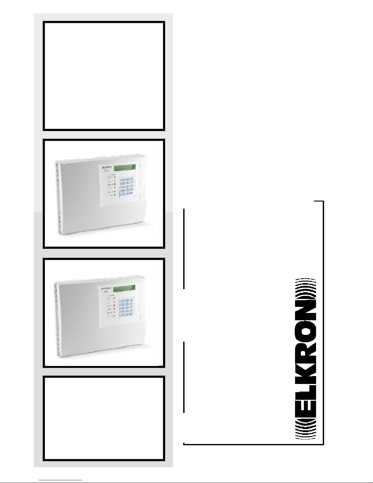
CT10-M
GSM telephone communicator
CT11-M
GSM/PSTN
telephone communicator
User
manual

(((ELKRON))) - CT10-M / CT11-M
2
Table of contents
1.0 Description of LEDs and buttons ............................................ 3
1.1 Description of the LEDs .................................................... 3
12 Description of the buttons ................................................ 3
2.0 Language selection............................................................. 4
2.1 Language selection ......................................................... 4
2.2 Viewing system status ..................................................... 4
3.0 User programming.............................................................. 5
3.1 User programming list ..................................................... 6
3.2 Telephone number programming list ..................................... 7
3.3 Output switching menu ................................................... 8
3.4 Answering service menu (for remote controls) ....................... 9
3.5 Engineer code enabilng menu ........................................... 9
3.6 User code changing menu ............................................... 10
3.7 SIM card expiration menu................................................. 11
3.8 Test call menu .............................................................. 12
3.9 SMS message editor menu................................................ 13
3.10 Voice message programming menu ...................................... 15
4.0 Cycle call stopping ............................................................. 15
5.0 Answering machine e remote control..................................... 16
Alfanumeric coding table ..................................................... 19
DIRECTIVE R&TTE 99/05/EC COMPLIANCE
Informative note
Ministerial type-approval for transceivers and telecommunication terminals
was abolished on 8 April 2000.
The CT11-M terminal is designed and certified for PSTN (Public Switched
Telephone Network) use employing DTMF (Dual Tone MultiFrequency)
signalling. The terminal complies with the Pan-European Connection Directive
R&TTE 99/05/CE – ETSI TBR21 for use as a standalone terminal in an
analogue PSTN.
Refer to the technical instructions accompanying the product for possible
specific hardware and software programming.
(((ELKRON))) - CT10-M / CT11-M
3
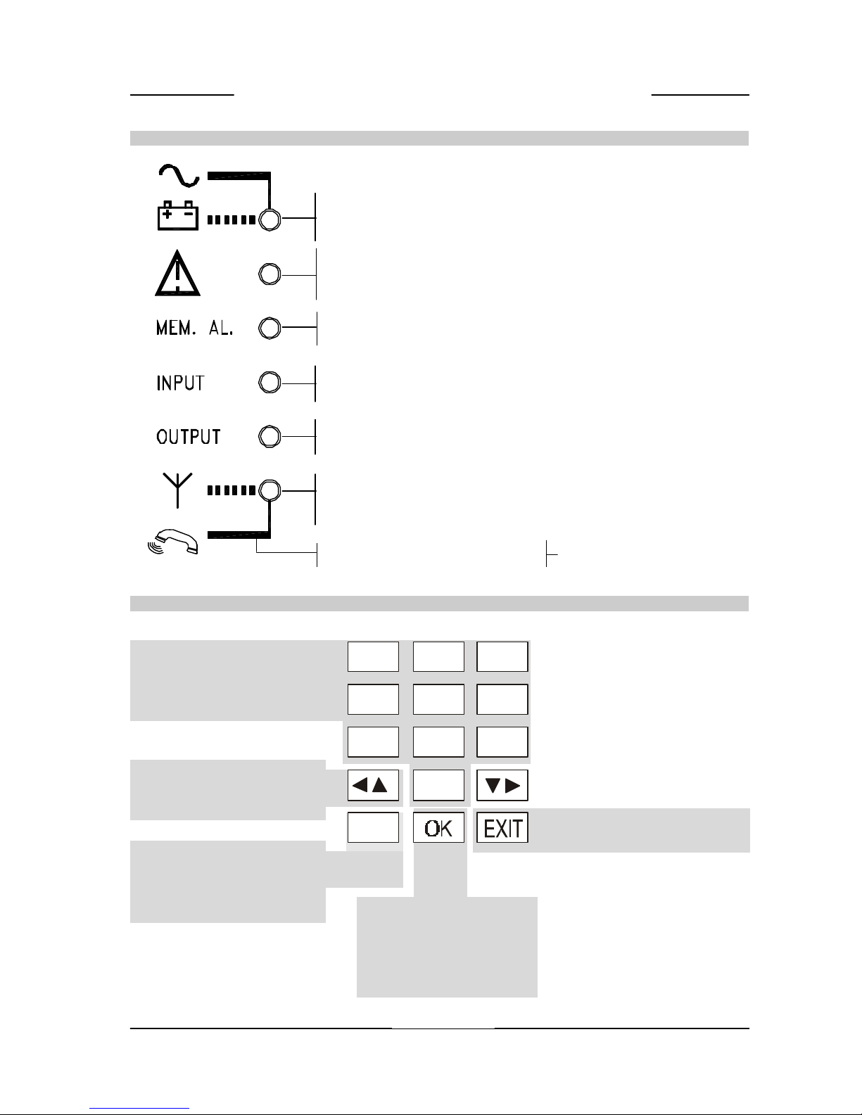
1.0 Description of LEDs and keys
NETWORK/BATTERY
ON = NETWORK OK
OFF = NO NETWORK
BLINKING = LOW BA TTERY
1.1 DESCRIPTION OF THE LEDS
TELEPHONE FAILURES
OFF = NORMAL
SLOW BLINK = FAILURE/MEMORY
FAST BLINK = FAILURE PRESENT
ALARM MEMORY
OFF = NORMAL
SLOW BLINKING = ALARM
INPUT STATUS
OFF = INPUT OK
ON = INPUT ALARM
OUTPUT STATUS
OFF = OUTPUTS OK
ON = SWITCHED OUTPUTS
TRANSMISSION STATUS
OFF = GSM EITHER INACTIVE
SLOW BLINKING = GSM ACTIVE
FAST BLINKING = TRANSMITTING
1.2 DESCRIPTION OF THE KEYS
OK key used to confirm
parameter modifications
during programming and to
start listening to and
recoding messages
Arrow keys used to scroll the
programming menu and select
the functions to be programmed
EXIT key used to quit the
programming menus
Number pad keys for entering
access code, telephone
numbers and selecting
programming parameter values
Key for accessing the SYSTEM
STATUS MENU (in combination
with number keys) and for
deleting telephone numbers
1
7
4
2
8
5
0
3
9
6
C
ABC DEF
GHI JKL MNO
PQRS TUV WXYZ
+
ON = PSTN- DTMF DIAL LINE SOCKET
BLINKING = PULSE SELECT (COUNTER)
(CT11-M only)
(((ELKRON))) - CT10-M / CT11-M
4
2.0 Language selection - viewing system status
2.1 LANGUAGE SELECTION
• The interface language can be selected in any condition without needing to enter a
code. Simply press “C” followed by 9. The languages will be displayed cyclically each
time the button is pressed. Either press E to quit or wait for the one minute time-
out.
INPUTS NOT QUITTED
(e.g. Input 1)
ALARM MEMORY
(e.g. Input alarm 2)
CLEAR ALARM MEMORY AND
NETWORK/BATTERY FAILURE
WARNING LEDS
2.2 VIEWING SYSTEM STATUS
• The “SYSTEM STATUS” menu can be accessed in any condition without entering a code. Simply
press “C” followed by a number key (from 1 to 8). Either press to quit the menu or wait for
the time-out (one minute).
IN. Not QUITTED
IN.: 1
alarm memory
IN.: 2
alarm memORY
IN.:
BUTTONS TO
PRESS
LANGUAGE
FRENCH
GERMAN
DISPLAY
TRANSMETTEUR
GSM/RTC
COMMUNICATOR
GSM/PSTN
KOMMUNIKATOR
GSM/PSTN
SELECT LANGUAGE
COMUNICATORE
GSM/PSTN
C
+
9
WXYZ
+
9
WXYZ
+
9
WXYZ
+
9
WXYZ
+
9
WXYZ
+
9
WXYZ
ENGLISH
SPANISH
COMUNICADOR
GSM/PSTN
PORTUGUESE
COMUNICADOR
GSM/LINEA FIXA
BUTTONS TO
PRESS
EVENT TYPE
DISPLAY
(((ELKRON))) - CT10-M / CT11-M
5
SWITCHED OUTPUTS
(e.g. Output 4 switched)
SIM CARD EXPIRATION
(e.g. Card expires in December 2003)
GSM DATE AND TIME
C
+
3
DEF
C
+
4
GHI
C
+
5
JKL
C
+
6
MNO
C
+
7
PQRS
+
7
PQRS
+
7
PQRS
+
7
PQRS
+
7
PQRS
+
7
PQRS
C
+
+
outputs on
U : 4
field COV. : ) )@
SIM EXPIRE DATE
12/03
GSM DATE-TIME
01/07/01 00:00
GSM ANOMALY
PSTN ANOMALY
CALLS LOG
CYCLE KO: 0/000
GSM KO: 000/000
PSTN KO 000/000
GSM FIEL K0: 0
GSM CONN. KO: OOO
PSTN TEST KO: OOO
CLEAR DATA
OK/EXIT ?
AT EACH PRESSURE OF THE KEY
7 APPEAR THE FOLLOWING
VISUALIZATION
IF ANOMALY PRESENT WARNING
(CT11-M only)
CYCLES WITH ANOMALIES/TOTAL CYCLES
CALLS WITH ANOMALIES/GSM CALLS MADE
CALLS WITH ANOMALIES/PSTN CALLS MADE
NUMBER OF “NO FIELD COVERAGE” FAILURES
N. OF DISCONNECTION FAILURES BETWEEN GSM
MODULE AND CT10-M/CT11-M OR MISSING SIM
CARD
NUMBER OF “NO PSTN LINE” FAILURES (CT11-M)
COUNTER RESET COMMAND (ACTIVE ONL Y
WHEN FAILURE AND ANOMALY CONDITIONS
HAVE BEEN RESTORED) AND TELEPHONE
FAILURE INDICA TOR LED
BUTTONS TO
PRESS
EVENT TYPE
DISPLAY
GSM FIELD COVERAGE AND NETWORK REGISTRATION
@ = home
^ = roaming
x = not registered
The message “Searching network…” will appear if the device is not registered.
REL. SW
V 1.00
SOFTWARE RELEASE (BOARD)
REL. FW
V 1.00
GSM MODULE CONTROL FIRMWARE
(((ELKRON))) - CT10-M / CT11-M
6
3.0 USER PROGRAMMING
NOTE: An alarm event occuring during programming will be signalled by means of the LEDs
on the panel. The respective outputs will switch. No calls will be made because the system
is being supervised at the time.
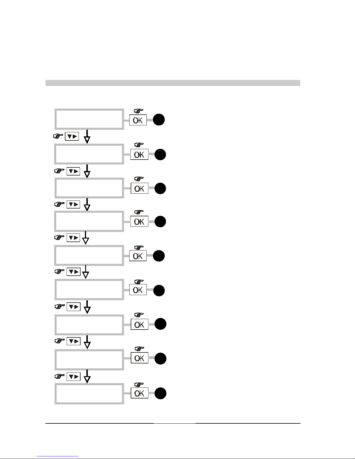
3.1 USER PROGRAMMING LIST
Enter the 6-digit user code x-x-x-x-x-x (default 111111)
USER MENU
TELEPHONE NR.
USER MENU
SWITCH OUTPUT
USER MENU
CODE CHANGING
USER MENU
CALL TEST
USER MENU
SMS MESSAGE
USER MENU
VOCAL MESSAGES
USER MENU
ANSWERING PROG.
USER MENU
ENGINEER ENABLED
USER MENU
SIM CARD
6
7
11
12
14
pag.
pag.
pag.
pag.
pag.
8
pag.
10
pag.
9
pag.
8
pag.

(((ELKRON))) - CT10-M / CT11-M
7
3.2 TELEPHONE NUMBER PROGRAMMING MENU
This menu is used to programme/edit the telephone numbers which will be dialled
automatically by the communicator following an alarm. Up to twelve numbers can be
programmed, maximum 28 digits each.
EXAMPLE
to scroll numbers forwards
to scroll numbers backwards
EXAMPLE
to confirm the
selected number
to confirm
programmed
number
Use keys 0-9 to enter the required
telephone number digits.
Press to include a 2 seconds pause
during dialling.
To edit a telephone number, position the
cursor on the digit to be changed by
pressing and enter the new
digits.
Press
C
to delete the entire number..
Press
0
+
for at least one second to
enter the international prefix (+) (CT10M only)
Press
7
PQRS
for at least one second to
enter *.
Press
9
WXYZ
for at least one second to
enter #.
to return to
telephone number
programming
user MENU
TELEPHONE NR.
TELEPHONE NR.
n01:
TELEPHONE NR.
n02:
TELEPHONE NR.
n03:
TELEPHONE NR.
n12:
n 12: 0121 39282112
TELEPHONE NR.
n 12: 0121 39282112

(((ELKRON))) - CT10-M / CT11-M
8
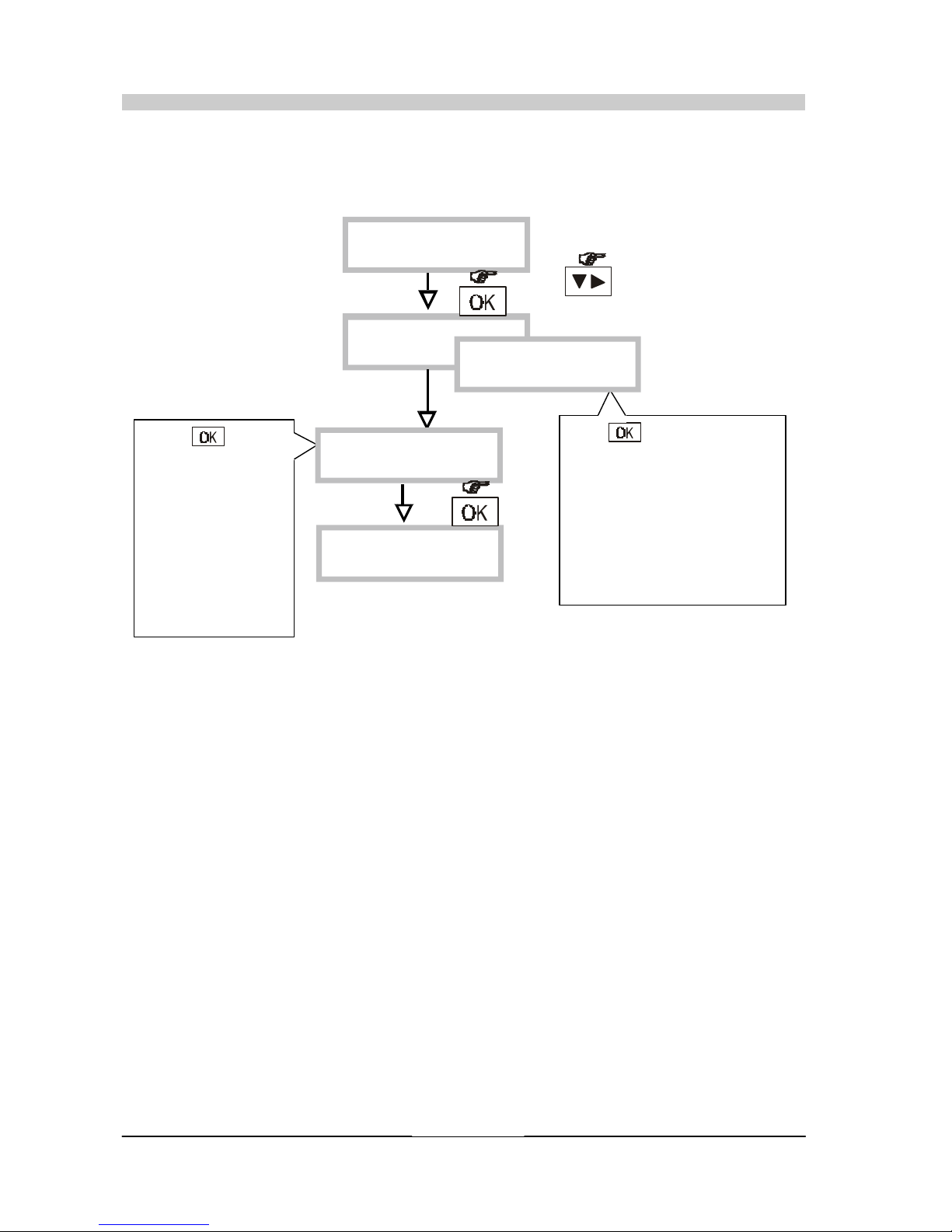
3.3 OUTPUT SWITCHING MENU
• This menu is used to change a remotely controllable output (ON/OFF). An output switched
on or off remotely can be returned to its original condition.
to select the outputs
to confirm the
output to switch
to return to the
output switching
menu
to confirm the
selection
The current output
status is displayed.
Press C to change.
user MENU
SWITCH OUTPUT
SWITCH OUTPUT
OUTPUT NR: 3
SWITCH OUTPUT
OUTPUT NR: 4
SWITCH OUTPUT
OUTPUT NR: 5
OUTPUT NR : 5
DISABLED
OUTPUT NR : 5
ENABLED
SWITCH OUTPUT
OUTPUT NR. 5

(((ELKRON))) - CT10-M / CT11-M
9
3.5 ENGINEER ENABLING
• By means of this procedure it is possible to enable the engineer code.Access to the
enginner menu will be disabled once the user code is entered.
USER MENU
ENGINEER ENABLED
ENGINEER
ENABLED ?
3.4 ANSWERING PROGRAMMING MENU (for remote controls)
• This procedure can be used to activate the answering service function permitting a
connection between the caller and the communicator to operate remote controls.
to confirm
The answering service function will be activated also if the “skip outgoing message”
is automatically activated. The number of rings on CM10-M are only indicative
USER MENU
ANSWERING PROG.
ANSWERING PROG.
OFF
ANSWERING PROG.
2 RING
ANSWERING PROG.
4 RING
ANSWERING PROG.
8 RING

(((ELKRON))) - CT10-M / CT11-M
10
3.6 USER CODE CHANGING MENU
• This procedure can be used to customise the USER access code (default 111111
to confirm the
entered code
Enter the new 6-digit
programming code by means of
the number keys 0- 9.
Re-enter the new code by means
of the number keys 0- 9.
to reconfirm the
entered code
USER MENU
CODE CHANGING
NEW CODE
- - - - - NEW CODE
* * * * * *
CODE CONFIRM
* * * * * *

(((ELKRON))) - CT10-M / CT11-M
11
3.7 SIM CARD EXPIRATION MENU
• If a pre-paid SIM card is used instead of a telephone subscription, the card will expire
either when the credit is used up (for the calls made) or automatically after a certain
time from the last request for credit (typically after 12 months). Refer to the conditions
of your telephone operator.
• This function can be used to program a date when the CT10-M will send an automatic
call to advice the user that the SIM card expiration date is approaching.
• A specific text message will be sent (number 4) to the telephones associated with
failure events (see “Failure/telephone number association” menu).
The current date and time must be entered before programming the SIM card expiration.
ENGINEER MENU
SIM CARD
SIM CARD
EXPIRE: mm/aa
to confirm
Enter the 4 digits corresponding
to the month and year of
expiration by means of the
numeric keys 0-9.
You are advised to enter the
month before that of actual
expiration of the SIM card.
SIM CARD
EXPIRE: 03/04
EXAMPLE
EXAMPLE:
SIM CARD EXPIRATION
MARCH 2004
The SIM card expiration text
message will be sent as soon as
the date shown on the cellular
telephone coincides with the
programmed date.
DATE TIME - GSM
DD-mm-YY hh:mm
Enter the digits corresponding to
the date and time (in 24 hour
format) using numeric keys 0-9.
The default date format is
“Europe”; press “C” to go to
“USA” format.
NOTE: All date and time fields must be entered to store the setting. Note that
12h time format (with “AM” and “PM”) is used if “USA” setting is selected (in
SYSTEM STATE menu).
DATE TIME - GSM
DD-mm-YY hh:mm
C
to confirm
(((ELKRON))) - CT10-M / CT11-M
12
3.8 CALL TEST MENU
• A voice test call can be made after installation or for a functional test of the communicator.
The basic message will be sent to the 12th programmed number.
Press : the
communicator will
make three calls to
the 12th number,
repeating the basic
voice message
three times. The
test call cycle can
be barred by dialling
12 in DTMF from the
telephone which is
receiving the call
The test call will not be made if the 12th telephone number is not programmed.
CT11-M only
to select the
telephone network
Press : the communciator
will make one call to the 12th
number, repeating the basic
voice message three times.
The test call cycle can be
barred by entering dial 12 in
DTMF from the telephone
which is receiving the call .
See for calling method with
answer check function.
USER MENU
CALL TEST
CALL TEST
GSM MODE
GSM MODE
SEND ? ok/eXIT
COMMUNICATOR
GSM/PSTN
CALL TEST
PSTN MODE

(((ELKRON))) - CT10-M / CT11-M
13
3.9 SMS MESSAGE EDITOR MENU
• This function can be used to edit the text messages that the communicator will send
following ALARM/FAILURE/SIM CARD EXPIRATION events.
• There are four messages. The association between the text message number and the
event is shown in the following table.
Message Associated event Example
TEXT 01 INPUT 1 ALARM “WARNING BURGLAR ALARM”
TEXT 02 INPUT 2 ALARM “WARNING ROBERY IN PROGRESS”
TEXT 03 TECHNICAL FAILURE “WARNING NO FIELD COVERAGE”
TEXT 04 SIM CARD EXPIRATION “WARNING CT10-M SIM CARD EXPIRATION”
• The message text for each ALARM/FAILURE/SIM CARD EXPIRATION event can be freely
edited (maximum 40 characters per message).
to select actions
to confirm
selection
to confirm
message
selection
to select messages
Enter the number by means of
the number keys 2- 9 by
pressing the button
corresponding to one, two,
three or four times according
to the position of the letter in
set. Press to go to the
next letter (see pag.19 for
special characters)
to confirm
message
USER MENU
SMS MESSAGE
SMS MESSAGE
READING SMS
SMS MESSAGE
WRITING SMS
SMS MESSAGE
DELETE SMS
WRITING SMS 01
WRITING SMS 02
WRITING SMS 03
WRITING SMS 04
WRITING SMS 02
“ “
EXAMPLE
MESSAGE SMS
WRITING SMS
EXAMPLE

(((ELKRON))) - CT10-M / CT11-M
14
to confirm the
action
to select the text message
to read
to confirm the
action
to confirm
message
selection
Press OK to confirm deletion
or press to quit without
deleting
EXAMPLE
to select the text message
MESSAGES LONGER THAN 16 CHARACTERS
An arrow will appear after the last
character if the message is more than
16 characters long. Press and
to see the rest of the message.
• Reading a text message
• Deleting a text message
READING SMS 02
READING SMS 03
READING SMS 04
“FALLING sim CT10-M”
MESSAGE SMS
READING SMS
READING SMS 01
CANCEL SMS 01
CANCEL SMS 02
CANCEL SMS 03
CANCEL SMS 104
“FALLING sim CT10-M”
MESSAGE SMS
DELETE SMS
DELETE SMS 04
ARE YOU SURE?
MESSAGE SMS
DELETE SMS

(((ELKRON))) - CT10-M / CT11-M
15
3.10 VOCAL MESSAGE PROGRAMMING MENU
• This function is used to record and play the voice messages which can be sent by the
communicator by means of the headphones provided .
• The available messages are associated to alarm events, remotely controlled output
status switching, a technical failure events and a telephone failure events.
Type of message .............. Duration
Basic message.................... 10 sec
Input 1 alarm ..................... 5 sec
Input 2 alarm ..................... 5 sec
Output U3 on ..................... 5 sec
Output U3 off .................... 5 sec
Output U4 on ..................... 5 sec
Output U4 off .................... 5 sec
Output U5 on ..................... 5 sec
Output U5 off .................... 5 sec
TECHNICAL FAILURE ............. 5 sec
TELEPHONE FAILURE (CT11-M only) 5 sec
Scroll the list and select the
message to be recorded or
played.
to confirm the
selection
Press to start recording.
The remaining time will
decrease on the display.
EXAMPLE
to confirm
selection
USER MENU
VOCAL MESSAGE
VOCAL MESSAGE
LISTENING
VOCAL MESSAGE
RECORDING
RECORDING
MAIN MESSAGE
RECORDING
MSG INPUT NR.1
RECORDING
MSG INPUT NR.2
RECORDING
MSG OUTPUT 3 ON
MSG OUTPUT 5 OFF
RECORDING- 04
msg INPUT 1
reCORDING
msg inPUT 1

(((ELKRON))) - CT10-M / CT11-M
16
4.0 Stopping che call cycle
• The call cycle can be stopped by dialling 12 in DTMF (called “Barring code”) on the
telephone receiving the voice call.
• Voice messages can be barred as shown below.
• The call in progress and the remaining call cycle (voice and text messages) will be
completed if the “Barring code” is entered.
• If the input that caused the alarm is subjected to TC, the call cycle in progress is barred
when the TC switched to ON.
• The call cycle can also be barred locally by means of the keypad by entering a valid code
(user code or ENGINEER code, where enabled).
BASIC
MESSAGE
SPECIFIC
MESSAGE
BEEP
WAIT
FOR BARRING
BASIC
MESSAGE
SPECIFIC
MESSAGE
BEEP
WAIT
FOR BARRING
BASIC
MESSAGE
SPECIFIC
MESSAGE
BEEP
WAIT
FOR BARRING
10 s 5 s 0.5s5 s
10 s 5 s 0.5s5 s
10 s 5 s 0.5s5 s
WARNING AUTOMATIC CALL
FROM THE SMITH’S HOME
BURGLAR
ALARM
BEEP
WAIT
FOR BARRING
10 s 5 s 0.5s5 s
DIAL 12
CYCLE BARRED
Voice message structure
sent three times:
Example of barring:

(((ELKRON))) - CT10-M / CT11-M
17
• Various devices can be switched on and off remotely (e.g. air conditioner, lights, irrigation system, etc.) by sending DTMF commands to any telephone and switching the
communicator outputs which are programmed as remotely controllable (U3, U4,
U5). If enabled, the communicator will answer incoming calls at any time, except for
when it is making alarm calls. To remotely control a device, call the CT10-M/CT11-M
GSM number or PSTN number (CT11-M only) and wait for an answer. GSM calls will be
answered after at least six rings (heard by the caller). PSTN calls will be answered after
a programmable number of rings (2-4-8, see paragraph 8.4).
• Answers are notified by a tone allowing the caller to dial the USER CODE (in DTMF)
within 30 seconds. A confirmation tone will be heard after each digit. A sequence of
three confirmation tones will be heard at the end of the code if the code is correct.
Otherwise a long error tone will be heard. Three attempts to enter the correct code can
be made before the call is ended.
• The remote control can be used to switch the required outputs (see sequence in the
following figure) after the code has been accepted. This operation requires a three-digit
code:
- 5: defines the type of “output switching” command.
- 3 or 4 or 5: defines the output number to be switched
- 1 or 0 is used to activate or deactivate the required output.
The communicator will give priority to an alarm triggered during the remote control
procedure. No on/off commands will be accepted and a WRONG CODE BEEP will be
output. Hang up.
• Each remotely controllable output can be programmed as maintained or timed.
- Status changes follow the command if the output is maintained.
- The on command (1) will activate the output and the timer while the off command
(0) will anticipate the time-out (if this has not already occurred) if the output is timed.
• The user has one minute from code recognition to complete the remote control operations. If no codes are sent by this time-out, the communicator will end the call in
progress and clear the line.
• The communicator will send a short confirmation tone after receiving each remote
control. A longer tone will be heard in the case of the following errors:
- programmed output other than “remotely programmable”
- wrong code
• If the code is accepted, the communicator will send the voice message recorded by the
user to confirm implementation of the control.
• At this point, the user will need to enter the “5” code again to switch other
outputs (or the same output) at the end of the voice message
NOTE: You are advised to deactivate the “ANSWERING SERVICE” function provided
by the GSM operator.
• SKIP ANSWERING MACHINE MESSAGE (CT11-M only)
Connect to the communicator as follows if an answering machine is fitted on the PSTN
line used by the CT11-M:
- call the PSTN telephone number
- wait for a single ring tone
- hang up quickly
- call the number again
5. 0Answering service and remote control
function

(((ELKRON))) - CT10-M / CT11-M
18
Remote control Function
Call GSM/PSTN
number
n
Answer tone
COMMANDS TO THE
COMMUNICATOR
SIGNALS FROM THE
COMMUNICATOR
MEANING OF THE SIGNALS
CONNECTION OK
RECEIVED CODE DIGIT
0.5s
BEEP
n 0.5sBEEP
n 0.5sBEEP
n 0.5s
BEEP
n 0.5sBEEP
n
0.5s
BEEP
Send six-digit
user code
(default
code
111111)
0.5s3 BEEPS
CORRECT CODE
RECEIVED CODE DIGIT
RECEIVED CODE DIGIT
RECEIVED CODE DIGIT
RECEIVED CODE DIGIT
RECEIVED CODE DIGIT
BEEEEP
WRONG CODE
1
2
5 RECEIVED0.5sBEEP
Send code 5
3
3
Send code
corresponding
to output to
be switched *
OR
OR
(repeat procedure from point 2 )
RECEIVED
0.5s
BEEP
4
4
5
OR
0
Send code :
1 = on
or
0 = off
5
1
OR
0.5s3 BEEPS
COMMAND
DONE
+ ASSOCIATED VOICE
MESSAGE
* More than one output can be switched (or the same output more than once) during the
same call. Simply repeat the following operations sequence:
for each output to be switched.
3
4
5

(((ELKRON))) - CT10-M / CT11-M
19
ALPHANUMERIC CODING TABLE
T U V 8
1
2
ABC
3
DEF
4
GHI
5
JKL
6
MNO
7
PQRS
8
TUV
9
WXYZ
+ - & @ / % Ø
? ! “ . ( )
1
A B C 2
D E F 3
G H I 4
J K L 5
M N O 6
P Q R S
W X Y Z
7
*
9
#
KEY
NUMBER OF TIME TO PRESS KEY
1 2 3 4 5 6 7 8
WHITESPACE
0
+

(((ELKRON))) - CT10-M / CT11-M
20
ELKRON SPA
Via Carducci, 3 - 10092 BEINASCO (TO)
TEL. 011.3986711 - FAX 011.3499434
EMAIL: info@elkron.it -
EMAIL Assistenza Tecnica: stac@elkron.it
UNI EN ISO9001 UNI EN ISO14001
CERTIFICAZIONI DI QUALITA' AZIENDALE
 Loading...