

Page 1

$10.00
ELK - ML1
Data Logger & External Modem/Parallel
Printer Interface
PO Box 100
3266 US Hwy. 70 West
Hildebran, NC 28637 USA
Telephone 828/397-4200 FAX 828/397-4415
http://www.elkproducts.com Email: sales@elkproducts.com
Elk Products, Inc Page 1 ML1 Instructions rev. 1.0 L493
Page 2

Introduction
The Magic Module family of low cost field programmable controller modules offers a unique controller and
data acquisition product line to markets not normally using such technology due to cost and complexity.
log any data bus event on the RS-485 data bus. Over 5000 data bus events may be logged into the ML1’s EEProm
Memory.
may be the Dallas iButton and the 26 bit Wiegand Prox Card ID devices. These access control devices are
attached to the MM443 Programmable Controller. The logged data in the ML1 may be downloaded into a PC through
the RS-485 data bus or through an external modem attached to the ML1. The modem interface offers passcode
protection and gives three authorization levels to users that might be accessing the Magic Module System.
is part of the Elk Product’s Magic Module Development Software. The written program is then downloaded to the
modules by way of the RS-485 data bus and programmed into re-programmable Electrically Erasable Programmable
Read Only Memory (EEProm memory). Up to 31 modules of the same type may be data bussed together.
The Code Editor uses the Code Writer, which constructs programs from a visual question list into a lower level
Intermediate Code. The Intermediate Code, known as SIMPLE
Intermediate Code into code byte’s that the micro processor reads out of reprogrammable EEProm memory and
executes the code through a built in operating system. The latest updates to the Elk Product’s Magic Module
Development Software are available at: www.elkproducts.com.
Components Available:
Note: Specifications and features may change without notice. All rights are reserved by Elk Products, Inc.
Dallas iButton is a trademark of Dallas Semiconductor Inc., Dallas, Texas
The ELK – ML1 data logger & external modem/parallel printer interface enables the Magic Module System to
A primary application of the ML1 data logger is to log access control events from the ELK TouchKey, which
The Magic Module System Modules are programmed by way of the ELK Code Editor and Code Writer, which
, is a Basic-like high level language that compiles the
• MK400S – Starter Development Kit for the MM443S Magic Module, includes Savoy Cyberhouse
Software.
• MK410 - Pre-programmed X-10 Transceiver. Four inputs, four relay outputs, sends and receives X-10.
• MK420 - Pre-programmed access control with 10 Dallas iButton’s.
• MM220 - 2 digital inputs, 2 relay outputs, stand-alone.
• MM443 - 4 analog inputs, 4 relay outputs, RS-485 data bus, X-10, Dallas iButton.
• MM443S - MM443 with Savoy Software.
• MM447 – The MM443, MV480, and the ML8 combined on one PC board. Fits in Caddx Control box.
• MV120 - 32 Channel Recordable Voice Annunciator - 120 seconds record time, RS-485 data bus.
• MV480 - 240 Channels Recordable Voice Annunciator - 480 seconds record time, RS-485 data bus.
• MK485 – Everything in the MK400S except the MM443S Magic Module
• MC100 - Real Time Clock - Plugs into the MM443 to give real time clock capability. Includes standby
battery.
• MA100 - Dallas iButton Reader Interface and iButton Reader - Interfaces Dallas iButton to MM443.
Includes MA110 and MA190.
• MA101 - Package of 10 Dallas iButton’s.
• MA110 – iButton Reader and stainless steel faceplate.
• MA190 – iButton Reader Interface and cord.
• MT100 - Magic Module Remote Temperature Probe.
• MA290 –26 bit Wiegand Reader Interface for prox cards, with cord to Magic Module MM443.
• MKHOME1 – Preprogrammed home automation package. Works with the Caddx Security Control.
• ML1 - Data logger & modem/parallel printer interface.
• ML8 - Caddx Security Control Interface.
Elk Products, Inc Page 2 ML1 Instructions rev. 1.0 L493
Page 3

Table Of Contents
INTRODUCTION.......................................................................................................................................................................................2
ELK - ML1 - DATA LOGGER & EXTERNAL MODEM/PARALLEL PRINTER PORT INTERFACE.....................................4
ML1 FEATURES ........................................................................................................................................... 4
ML1 SPECIFICATIONS .................................................................................................................................. 4
ML1 DESCRIPTION....................................................................................................................................... 5
ML1 BOARD DESCRIPTION .......................................................................................................................... 6
Data Bus Terminal Description ............................................................................................................... 6
Data Bus Address Jumpers ...................................................................................................................... 7
S1 – Print Button and S2 – Pause Button ................................................................................................ 7
S3 – Abort Button..................................................................................................................................... 7
Clear Logged Data .................................................................................................................................. 7
Power LED – LED 1 ................................................................................................................................ 7
Log Status LED – LED 2 ......................................................................................................................... 7
Printer Status LED – LED 3 .................................................................................................................... 7
Modem Status LED – LED 4.................................................................................................................... 7
Sign-On Status LED – LED 5 .................................................................................................................. 8
Real Time Clock....................................................................................................................................... 8
PROGRAMMING THE ML1 ...................................................................................................................................................................9
REQUIREMENTS:........................................................................................................................................... 9
ELK PRODUCTS, INC. DEVELOPMENT SOFTWARE......................................................................................... 9
MODE SELECTION ........................................................................................................................................ 9
CODE EDITOR............................................................................................................................................. 10
CODE WRITER............................................................................................................................................ 10
File Select............................................................................................................................................... 11
Modem Setup Screen.............................................................................................................................. 11
User Setup Screen .................................................................................................................................. 12
Logging – Search Order ........................................................................................................................ 12
Logging – Log Filter.............................................................................................................................. 13
PRINTER STRING COMMANDS .................................................................................................................... 17
LOG STORAGE LOCATIONS......................................................................................................................... 17
PRINTER STRING TEXT ............................................................................................................................... 17
FORMAT CONTROL CODES ......................................................................................................................... 17
Format Code Definitions ....................................................................................................................... 17
Control Codes Output Definition..................................................................................................... 18
Time and Date Control Codes ............................................................................................................... 19
Advanced Text Control Codes................................................................................................................ 19
Compare String Control Codes.............................................................................................................. 20
PRINTER STRING EXAMPLE 1 ..................................................................................................................... 21
PRINTER STRING EXAMPLE 2 ..................................................................................................................... 23
TRANSMIT REMOTE CONTROL (XMIT) ........................................................................................................................................25
UPLOAD LOG ............................................................................................................................................. 25
MODEM CONNECTION ........................................................................................................................................................................26
Modem Connect ..................................................................................................................................... 26
Modem Hangup...................................................................................................................................... 26
MAGIC MODULE DATA BUS COMMANDS..................................................................................................................................... 27
ASCII CHARACTER SET ......................................................................................................................................................................28
Elk Products, Inc Page 3 ML1 Instructions rev. 1.0 L493
Page 4
ELK - ML1 - Data Logger & External Modem/Parallel Printer
Port Interface
ML1 Features
• Up to 5000 logged events (with 3 X 128K EEProms).
• Parallel Printer Port Interface.
• Serial RS-232 Modem Port for external modem. 28K baud minimum.
• Modem Password protected with 2 user levels.
• Printer output may be formatted to any print layout.
• Networked to optional PC and up to 64 other Magic Module System devices through a RS-485 data bus.
• Automatic Code Writer code development.t
• Program stored in non-volatile EEProm memory.
• Plastic white ABS enclosure with cover. 6.5 in. X 4 3/8 in. Mounts to single or double gang electrical
box. Optional DIN Rail Mounting. PCB mounts into 4 inch SnapTrack.
ML1 Specifications
• Magic Module System RS-485 Data Bus Type 6.
• Operating Voltage - 9.6 to 15 Volts D.C.
• Operating Current - 40 ma. Nominal.
• Operating Temperature - 32F to 122F (0C to 50C).
• Environment - Indoor non-condensing.
• 9 pin male D connector on RS-232 serial por.t
• 25 pin female D connector parallel port printer connector.
• RS-485 Data Bus - up to 64 different device loads. Maximum length - 4000 feet.
• Real Time Clock received from the RS-485 data bus.
Elk Products, Inc Page 4 ML1 Instructions rev. 1.0 L493
Page 5

ML1 Description
Usage – ML1 may be used as Magic Module data bus data logger, as a parallel printer interface to print the
logged messages as the messages are logged or after they have accumulated, and as an external modem interface to
control and reprogram the Magic Module System.
Printer Interface – A printer with a parallel port connection may be connected to J6, a 25 pin D connector.
The printer may be programmed to print each logged message as they are entered or print all the messages upon
command.
Modem Interface – J4, a 9 pin D connector is a serial, RS-232 port to connect to a Hayes compatible external
modem running at 28K baud or faster. The modem will answer only and will request a password. The password can
be in two levels: User and Installer Level. The passwords are set when programming the ML1 with the
Elk Product’s Magic Module Development Software using the Code Writer in the ML1 Mode.
Logging – Over 5000 data bus events may be logged into the ML1’s EEProm memory and later printed to the
parallel printer port or downloaded to a PC by way of the RS-485 data bus or an external modem connected to the
ML1’s serial modem port.
RS-485 Data Bus – The ML1 constantly monitors the RS-485 data bus to find any data packets that match
criteria that was programmed into the ML1 to log data when the criteria was matched. Excellent articles are available
from the National Semiconductor Website on the proper way to install the RS-485 Data bus:
http://www.national.com/an/AN/AN-979.pdf
http://www.national.com/an/AN/AN-1057.pdf
Programming – Programming is done through the Code Editor and Code Writer programs, and then loaded
into the ML1 through the Transmit program by way of the RS-485 data bus. The program is transferred from the PC to
the ML1 using the PC’s serial port and a RS-232 to an RS-485 converter box (ELK Part # MB485). These programs
are available in the Elk Product’s Magic Module Development Software.
Reset - In the event that a defective program has been loaded into the ML1 memory and the data bus can no
longer be accessed for reprogramming, the module’s program memory can be cleared and reset by shorting the solder
pads located at “TP1” and “TP2”, then powering up the module.
Elk Products, Inc Page 5 ML1 Instructions rev. 1.0 L493
Page 6
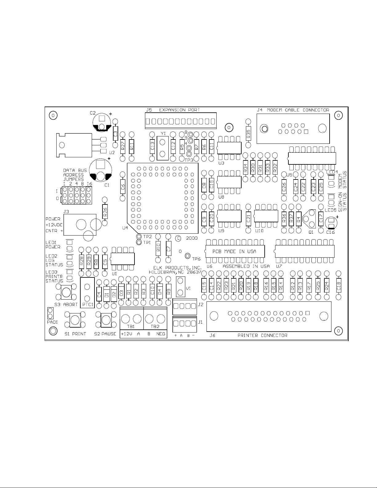
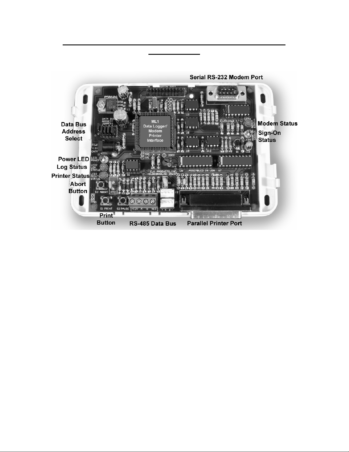
ML1 Board Description
+12 VDC may be supplied at four (4) locations on the ML1 PC Board:
1. RS-485 Data Bus Terminal Strip terminals 1 and 4 (TB1 and TB2).
2. RS-485 Data Bus Jumper Header J1, Pins 1 and 4.
3. RS-485 Data Bus Jumper Header J2, Pins 1 and 4.
4. J3 Power Connector for plug in power supply, center pin is +12VDC.
Data Bus Terminal Description
1. +12VDC (TB1 Left) - Minimum 100 milliamps. Will vary according to equipment connected to the ML1.
2. Data Bus A (TB1 Right) - RS-485 data bus. All “A” terminals must be connected together when the data bus
is in use.
3. Data Bus B (TB2 Left) - RS-485 data bus. All “B” terminals must be connected together when the data bus is
in use.
4. Neg (TB2 Right) - Common ground or power supply negative terminal.
Elk Products, Inc Page 6 ML1 Instructions rev. 1.0 L493
Page 7

Data Bus Address Jumpers
Each ML1 connected to the RS-485 data bus must have a unique address set on each ML1. This address is set on
the ML1 PC Board with five (5) jumpers. The address is set with a binary code; each jumper has a value as follows:
Jumper 1 (left jumper) = 1
Jumper 2 = 2
Jumper 3 = 4
Jumper 4 = 8
Jumper 5 = 16
By placing the appropriate jumper(s) in the upper or 1 position, the address setting may be set by adding up the
jumper values.
Example: Set data bus address 5.
Jumper 1 and jumper 3 will be placed into the “1” position. Add up the value: 1 + 4 = 5.
Set data bus address 17.
Jumper 1 and jumper 5 is placed into the “1” position. Add up the value: 1 + 16 = 17.
Note: After changing the data bus address jumper settings, the power must be turned
off and turned back on before the new jumper settings will take effect.
S1 – Print Button and S2 – Pause Button
Toggles the Parallel Printer On and Off. If the printer is enabled to print as you go, and the printer is turned off
as indicated by the Printer Status LED being Off, the print messages to the printer may be stopped by
pressing the Print or Pause Button. Press the Print or Pause Button again to enable the printer as indicated
by the Print Status LED being On. Note: Most printers have a built-in buffer so several lines of print data may
be buffered in the printer to be printed after the Print or Pause Button has been pressed.
S3 – Abort Button
When pressed, the ML1 will reset the location in the logged data to start printing at the beginning of the
logged data file in EEProm. When the Abort Button is pressed, the Print Status LED will go out. Press the
Print or Pause Button to get a complete print out of the logged data. Note: Printing the logged data does not
clear the logged data out of the EEProm memory.
Clear Logged Data
All the logged data that is stored in the EEProm may be cleared with the following procedure:
1. Press the Print or Pause Button. Note that the Print Status LED will go out.
2. Press at the same time: Pause, Print and Abort Buttons.
3. Within 1.5 seconds press the Abort Button.
4. In approximately 10 seconds the Print Status LED will come on indicating that the log EEProm
memory has been cleared.
Power LED – LED 1
Is ON when +12 VDC power is available to the ML1.
Log Status LED – LED 2
Normally ON when logging is enabled. Blinks when the log EEProm memory is 80% full.
Printer Status LED – LED 3
OFF when the printer is disabled. On when the printer is enabled. Blinking when no printer is attached or
there is a problem with the printer.
Modem Status LED – LED 4
modem is connected or there is a problem with the external modem.
Elk Products, Inc Page 7 ML1 Instructions rev. 1.0 L493
Is ON when an external modem is connected to the RS-232, 9 Pin serial port at J4. Blinking when no external
Page 8

Sign-On Status LED – LED 5
Is ON when someone has signed on through the external modem.
Real Time Clock
MC100 Real Time Clock Board plugged into it or from the time broadcasts from a ML8 Caddx Security Control. Other
devices may also broadcast the real time clock data for the ML1 to reference.
The real time clock is set from the time broadcasts from an ELK MM443 Magic Module that has an ELK
Elk Products, Inc Page 8 ML1 Instructions rev. 1.0 L493
Page 9
Programming The ML1
Requirements:
• Windows 95 or 98, minimum suggested Pentium 75 Mhz
•
16 meg Ram
•
50 meg Hard Drive Space
•
CD Drive for program installation
•
RS-232 Serial Port
•
Display 800 X 600 X 16 bit SVGA or greater
•
Mouse
Elk Products, Inc. Development Software
The ML1 is programmed using the Elk Product’s Magic Module Development Software. The program will be
written using the Code Editor and the Code Writer. The Code Writer will automatically write the program to be
loaded into the ML1 after you have answered the questions in the Code Writer section.
All Examples are shown with ELK Development Software version 5.0.18 or later.
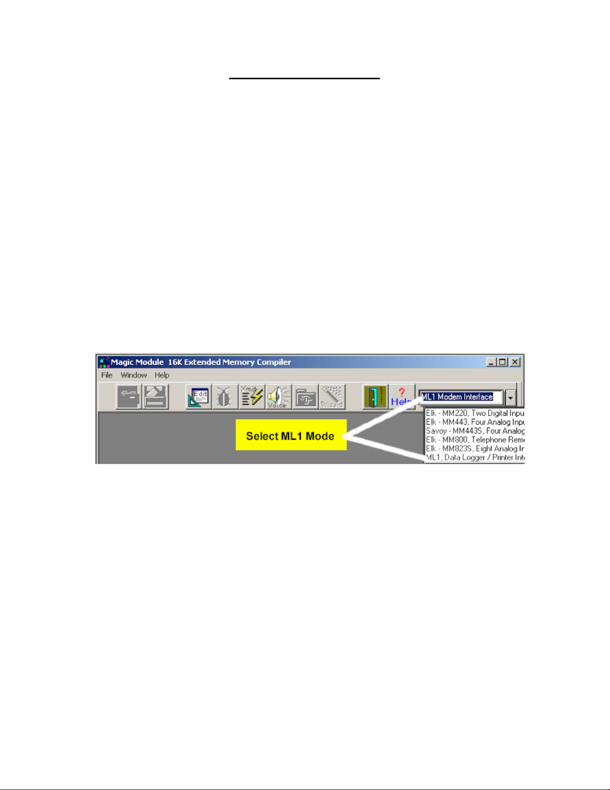
Mode Selection
When the Main Screen displays, select the ML1 Modem Interface mode. Next click the “Edit” button to enter
the Code Editor Program.
Elk Products, Inc Page 9 ML1 Instructions rev. 1.0 L493
Page 10

Code Editor
The Code Editor edits and builds the intermediate code so that it can be transmitted to the ML1 by way of
the Transmit Program (Xmit button).
When the Code Editor starts and asks for a NEW program or OPEN an existing program, answer NEW.
Code Writer
For specific details on how to use the Code Editor, see the ELK MM443 Magic Module Instruction Document L391.
The entire ML1 Application Program is written automatically using the Code Writer Part of the Code Editor Program.
Note: In order to write a proper ML1 program, a complete understanding of the data bus packets are required.
ELK Products offers technical assistance in writing application programs for the ML1. When starting a ML1
Application for the first time, contact the ELK Products Technical Service for any assistance.
Elk Products, Inc Page 10 ML1 Instructions rev. 1.0 L493
Page 11

File Select
The ML1 selections may be saved with the File/Save As MLP Settings File, and the ML1 selections may be
retrieved with the File/Open MLP Settings File in the Code Writer section.
Modem Setup Screen
User Password – Up to 16 characters may be entered for the normal user password. The user is normally the end
user or person that should not have access to all areas of the Magic Module System. The user password is sent when
logging into the ML1 from an external modem. An incorrect password will cause the modem to hang up. The default
password is User. This is case sensitive, so type the characters exactly as entered.
Superuser Password – Up to 16 characters may be entered for the Superuser password. The Superuser is normally
the installer or administrator. This user may access all levels of the data bus and Magic Module System. The
Superuser password is sent when logging into the ML1 from an external modem. An incorrect password will cause the
modem to hang up. The default password is Superuser. This is case sensitive, so type the characters exactly as
entered.
Modem Setup String – Up to 104 characters may be entered for the modem setup string. This is the command that
must be sent to a modem to initialize it for proper operation.
The default modem setup string show above is for a US Robotics Sportster 28.8K baud external modem. Other
manufacturers may require different setup strings. Consult the modem manufacturers technical documentation to see
what setup string is required for the modem that you are using.
To change the modem setup string, highlight the area to be changed and type the new setup string data.
As new setup strings are found, they will be posted on our website: www.elkproducts.com
Elk Products, Inc Page 11 ML1 Instructions rev. 1.0 L493
.
Page 12

User Setup Screen
An understanding of the data bus command structure is required to program this screen. See Magic Module Data
Bus Protocol and Magic Module Data Bus Commands for more information.
This section enables or disables data bus commands to the User Level or a person that has signed in through the
external modem with a User Password.
To allow or disallow data bus commands, or all modules of a Type and or any addresses of modules select as follows:
1. To allow a command to work select the command from the Command drop down box and click the
Command Always Allowed click button.
2. Select the Type To if a particular module type is to be selected.
3. Select the Address To if a particular address is to be selected.
4. Click on the Insert Button.
5. The data will appear on the list.
To edit a selection on the list, double click the list line. The data will appear on the edit line.
To delete a list line item, highlight the list line and click the Delete Button.
Logging – Search Order
The order in which the ML1 searches the incoming data to be logged may be changed in order to give certain data
more priority on the selection process. Normally changing this selection process is not required.
In the example above the search order of the incoming data will be the Command, Type To, Address To, Type From,
and Address From. When the incoming data matches the Log Filter Data, the data is logged into the log EEProm.
Elk Products, Inc Page 12 ML1 Instructions rev. 1.0 L493
Page 13

Logging – Log Filter
The Log Filter selects what data is to be logged and what Printer String is to be used when the data is printed. Print
Strings can be from 1 to 254, with Print String 255 reserved by the ML1.
Note: Before making Log Filter selections, make sure the Printer String that you want
to use for the print out of the logged data is available.
Setup the data bus data to log as follows:
1. Select the Command to key on from the Magic Module Data Bus Commands section. If the Command is
a wildcard or don’t care then select –none-.
2. In the same way if desired, select the Type To, Address To, Type From, and the Address From. If any of
these selections are a wildcard or don’t care then select –none-.
3. Select the Printer String that will be used to print the logged data.
4. Click the Insert Button to store the data into Log Filter List.
Double Clicking any selection in the Log Filter List will place the data on the Edit Line to be edited.
To delete an item in the Log Filter List, highlight the list line then click the Delete Button.
Selections may be made that will not ever allow logging by clicking the Never Log Click Button after the edit line
data has been entered.
Example: Log the Access Key data every time an access card is used.
1. From the Magic Module Data Bus Commands, the key data will be broadcast on the data bus with
Command 50 (32h). 50 is the decimal value, 32 hexadecimal is denoted as 32h.
2. Enter 50 (32h) into the Command drop down box.
3. Since we do not care about the Types and Addresses, leave those box set to –none-.
4. The Printer String that we will use is Print String 254 or FEh.
5. Click the Insert Button to store the new Log Filter Data in the Log Filter List.
When a Command 50 (32h) is sent on the data bus, the data packet will be logged into the EEProm memory in
the ML1.
Elk Products, Inc Page 13 ML1 Instructions rev. 1.0 L493
Page 14

Printer – Initialization
This screen is the setup screen for the Printer and Logging System.
¾ Printer Initialization String- Some printers must be initialized upon power up. If your printer must be
initialized with an initialization string, enter the initialization string here. Limited to 40 characters.
¾ Logging System Enabled – If checked, the ML1’s data logging system will be operational. For external
modem only applications, uncheck this feature.
¾ Use Complex Search Method – Currently not used.
¾ Reporting System Enabled – If checked, the printer output is operational.
¾ Output To Printer – If checked, prints the logged data to the Parallel Printer Port.
¾ Output To Serial Port – If checked, prints the logged data to the modem serial port. Normally a serial
printer would be connected to this port instead of the external modem.
¾ Output Formatted Data – If checked, prints the data as defined in the Print Strings. If unchecked, the
data will be output in raw format, not recommended.
¾ Print As We Go – If checked, as each logged data item is logged, it will be printed to the printer. If
unchecked, the logged data will not be sent to the printer without an external command.
¾ Erase As We Go – If checked, as each logged data item is printed, it will be erased from the EEProm’s
log memory. This is good for information that only wants a printed report and does not care about printing
the information later.
Note: Click items in the Printer Report Mode selection box
may be disabled.
Elk Products, Inc Page 14 ML1 Instructions rev. 1.0 L493
Page 15

¾
Printer – Printer Strings
This screen is the setup screen for the Printer Strings. A Printer String defines the format that the printer will use
to print the logged data.
A Printer String is made up of Print Commands and text data to print. Reference the section on Printer String
Commands and contact Elk Products Technical Department for help on creating your custom Printer Strings.
Elk Products, Inc Page 15 ML1 Instructions rev. 1.0 L493
Page 16

Magic Module Data Bus Protocol
Example Data Bus Command: *<31:1240300?30= This command requests the status of relays on a Magic
Module.
The Magic Module Data Bus Protocol is made up of the following elements:
Byte 0 -
* - Start Character. The “*” character marks the start of the Magic Module Data Bus Packet.
< - Length Character. This is the length of the data packet. In this case the number of characters until the
Byte 1 -
first digit of the CRC is 12. The first byte “*” is not counted. See Single Byte Characters below for
further information.
Byte 2 - 3 - Type To Character. This is the device type that the data packet is being sent to. In this case a type 3 is a
MM443 Magic Module. See Single Byte Characters below for further information. This is available to
the MM443 Magic Module as variable TypeTo.
1 - Address To Character. This is the device address that the data packet is being sent to. In this case a
Byte 3 -
MM443 Magic Module set to an address of 1 on the data bus. See Single Byte Characters below for
further information.
Byte 4 - : - Type From Character. This is the device type that the data packet is coming from. In this case a “:” or
type 10 is a PC computer connected to the data bus. See Single Byte Characters below for further
information.
Byte 5 - 1 - Address From Character. This is the device address that the data packet is being sent from. In this case
a PC computer set to an address of 1 on the data bus. See Single Byte Characters below for further
information.
Byte 6 & 7 - 24 - Command. This is the data packet command expressed in hexadecimal. In this case Command 24
hex or 36 decimal is a Request For An Output Relay State. See Data Bus Commands and Two Byte
Data below. This is available to the MM443 Magic Module as variable RCMD.
Byte 8 & 9 -
Byte 10 & 11 -
Byte 12 to 15 -
Carriage Return and Line Feed (13 and 10 decimal value) always terminate a data packet.
Single Byte Characters
Single byte characters have a decimal value from 0 to 31. We use the ASCII character set to represent these
characters as follows:
0 = value 0
1 = value 1
2 = value 2
3 = value 3
4 = value 4
5 = value 5
6 = value 6
7 = value 7
8 = value 8
9 = value 9
: = value 10
03 – Data 1. This is the data 1 expressed in hexadecimal. In this case it is the address of the relay to
request the state of. Address 00 is relay 1 and address 03 is relay 4. See Two Byte Data below. This
is available to the MM443 Magic Module as variable RDAT1.
00 – Data 2. This is the data 2 expressed in hexadecimal. In this case it is not used and a value of 00
is transmitted. See Two Byte Data below. Additional data bytes may be included in other commands.
This is available to the MM443 Magic Module as variable RDAT2.
?30= – CRC Value. This is the Cyclic Redundancy Check Value. It is a 16 bit or 4 character value
that insures the data that has been transmitted is correct. Four Single Byte Characters are combined
together to form the CRC Value. The value of the length character will always point to the first character
of the CRC Value. In this case ?30= value is equal to 62221 decimal and F30D hexadecimal.
; = value 11
< = value 12
= = value 13
> = value 14
? = value 15
@ = value 16
A = value 17
B = value 18
C = value 19
D = value 20
E = value 21
F = value 22
G = value 23
H = value 24
I = value 25
J = value 26
K = value 27
L = value 28
M = value 29
N = value 30
O = value 31
Elk Products, Inc Page 16 ML1 Instructions rev. 1.0 L493
Page 17

Two Byte Data
Command and data are expressed in two byte characters, which are a hexadecimal value. A hexadecimal character
can be from 0 to F (0123456789ABCDEF), which has a decimal value from 0 to 15. When the two hexadecimal
characters are combined together with a hexadecimal range from 00 to FF, they have a decimal value range from 000
to 255. All of the command and data are expressed in hexadecimal.
To convert a hexadecimal two byte value to decimal use the following procedure:
1. Multiply the left character value from the Hexadecimal Value Table below times 16.
2. Add the right character value from the Hexadecimal Value Table below to the value in step 1.
Hexadecimal Value Table
0 = value 0
1 = value 1
2 = value 2
3 = value 3
4 = value 4
5 = value 5
6 = value 6
7 = value 7
8 = value 8
9 = value 9
A = value 10
B = value 11
C = value 12
D = value 13
E = value 14
F = value 15
Printer String Commands
A Printer String is used to format the logged data into a readable string that makes sense when printed on the printer.
The ML1 stores the data in the EEProm in a different format from the way it was received from the Magic Module
System data bus.
Log Storage Locations
All logged data is stored as a single byte in the following logged data locations:
Log Storage Byte 9 = Type To, range 0 to 31 (1Fh)
Log Storage Byte 10 (Ah) = Address To, range 0 to 31 (1Fh)
Log Storage Byte 11 (Bh) = Type From, range 0 to 31 (1Fh)
Log Storage Byte 12 (Ch) = Address From, range 0 to 31 (1Fh)
Log Storage Byte 13 (Dh) = Command, range 0 to 255 (FFh)
Log Storage Byte 14 (Eh) = Data 0, range 0 to 255 (FFh)
…
Log Storage Byte 25 (19h) = Data 11, range 0 to 255 (FFh)
These values are used as the Offset value in the Printer String Format Codes.
Printer String Text
Text may be added at any location in the Printer String. The text may be individual ASCII characters separated by
commas 49, 50, 51, or strings of text delimited by brackets [and]. Example: [Relay is On] is printed by the printer as
Relay is On.
Format Control Codes
As data is logged into the ML1’s log memory, it is useful to retrieve the data and format it various ways before it is sent
to the printer. The Format Control Codes enables the programmer to specify how the data is formatted and sent to the
printer for any of the ML1’s logged data.
Format Code Definitions
¾ Offset – The log storage byte as explained in the Log Storage Locations above. Range 9 to 25.
¾ Value – The data value found at the Log Storage Location referenced by the value Offset. Range may be an
8 bit or 16 bit value. 0 to 255 or 0 to 65536
¾ Variable – A value that can be used for comparison or a fixed value. Range 0 to 255.
¾ Adder – A value that can be added to the logged data value. Range 0 to 255.
Elk Products, Inc Page 17 ML1 Instructions rev. 1.0 L493
Page 18

¾ Count – A value that is used to count the number of cycles. Range 0 to 255.
¾ Shift – A value that denotes the number of times to right shift some value. Range 0 to 7.
¾ Mask – A value that is used to mask out bits of a value. The Mask value is Anded with some value. Range 0
to 255. Example: A value of 255 and a Mask value of 3 will equal 3.
¾ Compare – The compare string value that selects which type of compare string to use and which text message
to use. Easiest to express as a hexadecimal value with the left digit selecting which type of comparison of
eight (8) types to use. Range 0 to 7. The right digit of the hexadecimal value selects which text string to print.
Range 0 to 7. See the Compare String Section below. Range 00h to 77h hexadecimal value.
Control Codes Output Definition
The control codes are listed in decimal with an optional hexadecimal value in parenthesis. Do not enter both values. A
hexadecimal or hex value is entered with an “h” suffix. Example: 20h = 32 decimal
128 (80h), Offset Output an ASCII hex
format “00
129 (81h), Offset Output an ASCII hex representation of the Value in the logged message following the
format “00h
130 (82h), Offset Output the single Value in the logged message exactly as it is stored in the logged
message.
131 (83h), Offset If the Value is a printable ASCII character, 32 <= Value <= 126, print it exactly. Otherwise
print an Open parenthesis “(“ or an upside down question mark.
132 (84h), Offset, Variable Output an ASCII decimal
representation will take up Variable characters, left padded with spaces. Variable range is
1 to 15.
133 (85h), Offset, Variable Output an ASCII decimal
will take up Variable characters, left padded with spaces. Variable range is 1 to 15.
134 (86h), Offset, Variable Output an ASCII decimal
High
decimal representation will take up Variable characters, left padded with spaces. Variable
range is 1 to 15.
135 (87h), Offset, Variable Output an ASCII decimal
High
decimal representation will take up Variable characters, left padded with spaces. Variable
range is 1 to 15.
136 (88h), Offset, Variable Output an ASCII decimal
Low
decimal representation will take up Variable characters, left padded with spaces. Variable
range is 1 to 15.
137 (89h), Offset, Variable Output an ASCII decimal
Low
decimal representation will take up Variable characters, left padded with spaces. Variable
range is 1 to 15.
138 (8Ah), Offset, Variable, Adder
Output an ASCII decimal
decimal representation will take up Variable characters, left padded with spaces. Variable
range is 1 to 15. Example: Value = 3, Adder = 1, Output value = 4.
140 (8Ch), Offset, Variable, Mask, Compare, Adder
Value ANDed with Mask is compared with Variable and the comparison result is printed
according to the Compare value in the Comparison Strings. See the Comparison String
Section.
141 (8Dh), Offset, Variable, Mask, Compare, Adder
Two ASCII hexadecimal
Value. Value ANDed with Mask is compared with Variable and the comparison result is
printed according to the Compare value in the Comparison Strings. See the Comparison
String Section.
142 (8Eh), Offset, Variable, Mask, Shift
Output an ASCII decimal
bit shifted right Shift times. The decimal representation will take up Variable characters,
left padded with spaces. Variable range is 1 to 15.
143 (8Fh), Offset, Variable, Mask, Shift
Output an ASCII decimal
bit shifted right Shift times following the format of “00h”. Variable is unused.
”.
”.
byte of a 16 bit value and Offset + 1 pointing to the Low byte of a 16 bit value. The
byte of a 16 bit value and Offset + 1 pointing to the Low byte of a 16 bit value. The
byte of a 16 bit value and Offset + 1 pointing to the High byte of a 16 bit value. The
byte of a 16 bit value and Offset + 1 pointing to the High byte of a 16 bit value. The
representation of the Value in the logged message following the
representation of the unsigned Value. The decimal
representation of the signed Value. The decimal representation
representation of the unsigned Value with Offset pointing to the
representation of the signed Value with Offset pointing to the
representation of the unsigned Value with Offset pointing to the
representation of the signed Value with Offset pointing to the
representation of the unsigned Value added to Adder. The
characters located at Offset and Offset + 1 are converted into
representation of the unsigned Value ANDed with Mask and then
representation of the unsigned Value ANDed with Mask and then
Elk Products, Inc Page 18 ML1 Instructions rev. 1.0 L493
Page 19

144 (90h) same as 128 (80h) Adds a leading space to the print output.
…
159 (9Fh) same as 143 (8Fh)
160 (A0h) same as 128 (80h) Prints and steps to the next location the Control Codes Variable number of
… 164, 14, 4 Prints 4 characters of the data starting at log storage location 14.
175 (AFh) same as 143 (8Fh)
176 (B0h) same as 128 (80h) Prints and steps to the next location the Control Codes Variable number of
…
191 (BFh) same as 143 (8Fh)
times.
Add the Variable value when needed.
times and adds a leading space to the print output. Add the Variable value
when needed.
Time and Date Control Codes
Note: The time and date is automatically printed with each line logged.
224 (E0h), 0 Hour from 00 to 23
224 (E0h), 3 Minute from 00 to 59
224 (E0h), 4 Month from 01 to 12
224 (E0h), 6 Month name “Jan”, “Feb”, “Mar”, … etc.
224 (E0h), 7 Day of the month from 01 to 31
224 (E0h), 9 Day of week “Sun”, “Mon”, “Tue”, … etc.
224 (E0h), 10 (0Ah) Year from 00 to 99
224 (E0h), 11 (0Bh) Year from 0000 to 9999
224 (E0h), 12 (0Ch) Years from leap year, 0 to 3
224 (E0h), 13 (0Dh) Hours and Minutes in HH:MM format
224 (E0h), 15 (0Fh) Month, Day, Year in MM/DD/YY format
224 (E0h), 17 (11h) Month, Day, Year in Jan 31 2000 format
224 (E0h), 18 (12h) Weekday, Month, Day, Year in Mon Jan 31 2000 format
224 (E0h), 19 (13h) Month, Day, Year, Hours and Minutes in MM/DD/YY HH:MM format
Advanced Text Control Codes
225 (E1h), Variable Send the ASCII character Variable to the printer. This how a value greater than or equal
226 (E2h), Variable Output up to Variable characters of the message using the 176 (B0h) Control Code
227 (E3h), Variable Output up to Variable characters of the message using the 163 (A3h) Control Code
228 (E4h), Variable Remove all extra spaces, 32 (20h), in the printer string that has been created to be sent
229 (E5h), Variable Output up to Variable characters of the message using the 163 (A3h) Control Code
to 128 would be sent to the printer.
starting with the Log Storage Byte 9. ASCII hex message format.
starting with the Log Storage Byte 9. Raw ASCII message format.
to the printer starting at location Variable in the printer string.
starting with the Log Storage Byte 10. Raw ASCII message format.
Elk Products, Inc Page 19 ML1 Instructions rev. 1.0 L493
Page 20

Compare String Control Codes
Compare Strings allow the printer output to print text messages according to numeric data that is received on the data
bus. For example: The state of a relay should be printed as “On” or “Off”. The value of the data on the data bus is
“00” or “01”, so a conversion with a compare string is necessary.
There are eight (8) types of comparisons, which will print combinations of the nine (9) Compare Strings as listed on the
screen below. Each type of Compare Strings have associated with it eight (8) text messages. As seen below “If
Binary Comparison is True” then text message #0 = “On” and text message #1 = “Closed”. The eight (8) text
messages for each type of Compare Strings may be accessed by clicking the click button to the left of each type of
Compare String.
Comparison Types
Compare value
0wh if Value ANDed with Mask is equal to Variable then print string in the “If Binary Comparison is True” where
if Value ANDed with Mask is not
1wh if Value ANDed with Mask is equal to Variable then print string in the “If Binary Comparison is False
if Value ANDed with Mask is not
2wh if Value ANDed with Mask is greater than Variable then print string in the “If Binary Comparison is Greater
if Value ANDed with Mask is not
3wh if Value ANDed with Mask is greater than Variable then print string in the “If Binary Comparison is Not
if Value ANDed with Mask is not
4wh if Value ANDed with Mask is less than Variable then print string in the “If Binary Comparison is Less Than”
if Value ANDed with Mask is not
5wh if Value ANDed with Mask is less than Variable then print string in the “If Binary Comparison is Not Less
Elk Products, Inc Page 20 ML1 Instructions rev. 1.0 L493
“w” is the string to print from 0 to 7. Example above: To print “Closed” if a comparison is true, the
0wh value = 01h. Adder value is ignored.
where “w” is the string to print from 0 to 7. Adder value is ignored.
“w” is the string to print from 0 to 7. Adder value is ignored.
where “w” is the string to print from 0 to 7. Adder value is ignored.
Than” where “w” is the string to print from 0 to 7. Adder value is ignored.
Greater Than” where “w” is the string to print from 0 to 7. Adder value is ignored.
Greater Than” where “w” is the string to print from 0 to 7. Adder value is ignored.
Than” where “w” is the string to print from 0 to 7. Adder value is ignored.
Greater
where “w” is the string to print from 0 to 7. Adder value is ignored.
Than” where “w” is the string to print from 0 to 7. Adder value is ignored.
Than” where “w” is the string to print from 0 to 7. Adder value is ignored.
equal to Variable then print string in the “If Binary Comparison is False”
” where
equal to Variable then print string in the “If Binary Comparison is True”
greater than Variable then print string in the “If Binary Comparison is Not
greater than Variable then print string in the “If Binary Comparison is
less than Variable then print string in the “If Binary Comparison is Not Less
Page 21

if Value ANDed with Mask is not
Than” where “w” is the string to print from 0 to 7. Adder value is ignored.
6wh if Value ANDed with Mask is greater
Than” where “w” is the string to print from 0 to 7.
if Value ANDed with Mask is less
where “w” is the string to print from 0 to 7.
Else print string in the “If Trinary Comparison is In Range” where “w” is the string to print from 0 to 7.
7wh if Value ANDed with Mask is greater
Than” where “w” is the string to print from 0 to 7.
if Value ANDed with Mask is less
where “w” is the string to print from 0 to 7.
Else print string in the “If Trinary Comparison is In Range” where “w” is the string to print from 0 to 7.
less than Variable then print string in the “If Binary Comparison is Less
than Variable then print string in the “If Trinary Comparison is Greater
than Adder then print string in the “If Trinary Comparison is Less Than”
than Variable then print string in the “If Trinary Comparison is Less
than Adder then print string in the “If Trinary Comparison is Greater Than”
Printer String Example 1
Print the On/Off status of the relays on a Magic Module MM443 when they are commanded to change from a
PC.
From the
Transmit Output Relay State 0A4h address H,L 0 = off, 1 = on
Enter the Command, Type To, Address To, and Printer String into the Logging/Log Filter tab in the Code Writer.
Then click the Insert button to store the Logging Filter data. The Magic Module MM443 is a Type 3, and the address
of the Magic Module will be assumed as address 1. Other addresses may be used. We will use Printer String 1 in
which we will setup later in the example.
Magic Module Data Bus Commands select
Elk Products, Inc Page 21 ML1 Instructions rev. 1.0 L493
Page 22

Insert the following Printer String into the Edit Line of the Printer String Screen:
[,Relay Output #], 138,14,1, 1, 32, 32, [,Status = ], 8ch, 0fh, 01h, 01h, 00h,20h
[,Relay Output #], 138,14,1, 1, 32, 32, [,Status = ], 8ch, 0Fh, 01h, 01h, 00h,20h after the date/time stamp on the
print out a text string will print “,Relay Output #”. Text is delimited by a starting bracket “[“ and an ending bracket “]”.
The leading comma is used if comma delimited text is desired.
[,Relay Output #], 138,14,1, 1, 32, 32, [,Status = ], 8ch, 0Fh, 01h, 01h, 00h,20h
138 (8Ah), Offset, Variable, Adder
Output an Ascii decimal representation of the unsigned Value added to Adder. The decimal
From the Data Bus Commands, we see that the address of the relay is at location 14 (0Eh). Since the relay
address ranges from 0 to 3, an Adder value of 1 converts the address to a range of 1 to 4, which is what the Magic
Module Relays are referred to as.
[,Relay Output #], 138,14,1, 1, 32, 32, [,Status = ], 8ch, 0Fh, 01h, 01h, 00h,20h
Individual ASCII characters may be entered by typing the ASCII character code as in 32,32, which is two
space characters. Next the text string “, Status = “ is send to the printer output. In this example the space characters
could have been placed in front of the “, Status = “ text string if desired.
[,Relay Output #], 138,14,1, 1, 32, 32, [,Status = ], 8ch, 0Fh, 01h, 01h, 00h,20h
140 (8Ch), Offset, Variable, Mask, Compare, Adder
Value ANDed with Mask is compared with Variable and the comparison result is printed according to the
From the Data Bus Commands, we see that the On/Off state of the relay is at location 15 (0Fh). The relay is
active or “On” if the On/Off state data value is = 1 as set in the Variable value. The On/Off state Value is ANDed with
the Mask value, which is equal to 1.
From the Compare Strings Section, Compare = 00h. Using w = #0 print value of “On”, this will be printed if
the relay data bus value = 1, and “Off” will be printed from the “If Binary Comparison is False
Adder value of 20h is ignored.
representation will take up Variable characters, left padded with spaces. Variable range is
1 to 15. Example: Value = 3, Adder = 1, Output value = 4.
Compare value in the Comparison Strings. See the Comparison String Section.
”, w = #0 value. The
Elk Products, Inc Page 22 ML1 Instructions rev. 1.0 L493
Page 23

0wh if Value ANDed with Mask is equal to Variable then print string in the “If Binary Comparison is True
if Value ANDed with Mask is not
Printer will print:
01/01/00 12:10 ,Relay Output #1 ,Status = On
where “w” is the string to print from 0 to 7. Example above: To print “Closed” if a comparison is true,
the 0wh value = 01h. Adder value is ignored.
equal to Variable then print string in the “If Binary Comparison is False”
where “w” is the string to print from 0 to 7. Adder value is ignored.
Printer String Example 2
Print the access key data when an access key is presented to the Magic Module. Used for access control data
logging.
From the
Dallas Key Data Found Broadcast 32H ID …7 Dallas ibutton bytes
This is the data that is broadcast on the data bus when a valid access key has been presented to the Magic
Enter the Command, and Printer String into the Logging/Log Filter tab in the Code Writer. Then click the Insert
button to store the Logging Filter data. Any command 050 (32h) will be logged with no regard to Type To or Address
To because –none- is selected. We will use Printer String 254, which we will setup later in example 2.
Magic Module Data Bus Commands select
Module.
”
Elk Products, Inc Page 23 ML1 Instructions rev. 1.0 L493
Page 24

Insert the following Printer String into the Edit Line of the Printer String Screen:
[Card Key Entered: ID#],80h,0eh,[ Card Code#],a0h,0fh,07h
[Card Key Entered: ID#],80h,0eh,[ Card Code#],a0h,0fh,07h
After the date/time has been printed, “Card Key Entered: ID#” will be printed.
[Card Key Entered: ID#],80h,0eh,[ Card Code#],a0h,0fh,07h
128 (80h), Offset Output an Ascii hex representation of the Value in the logged
message following the format “00
From the Log Storage Locations Section and the Data Bus Commands Section, we find that the ID number for the
access key data bus transmission is at logged data location 14 (0eh). The value logged is printed next.
[Card Key Entered: ID#],80h,0eh,[ Card Code#],a0h,0fh,07h
Next two spaces are printed, then “Card Code#”.
[Card Key Entered: ID#],80h,0eh,[ Card Code#],a0h,0fh,07h
a0h is the same command as 128 (80h) above except it prints 07h characters starting a logged data location
15 (0fh). See Control Codes Section above.
Printer will print:
01/01/00 12:10 Card Key Entered: ID# 01 Card Code #1234567
”.
Elk Products, Inc Page 24 ML1 Instructions rev. 1.0 L493
Page 25

Transmit Remote Control (Xmit)
The Transmit Program allows for downloading programs to the modules connected to the Magic Module Data Bus.
The system that program is being written for is identified in the upper right corner of the main screen in this case “ML1
Modem Interface”. The Magic Module Type that is being communicated with is located in the “Type” window and in
this case “Type 6, Data Logger”. If these settings are not displayed, change them before proceeding.
If you are using a serial RS-232 communications port other than Com1, change the setting using the “CommPort”
drop down button at the top of the Xmit Screen.
Make sure the Address setting on the Xmit Screen matches the address set into the ML1’s “Data Bus Address
Jumpers”.
ML1 Selected
Type 6 –Data Logger Selected
Click the “Transmit” Button to download the ML1 Program written with the Code Editor down to the ML1. Select the
name of the ML1 .src file where the program was saved.
As data bus events occur, they will be logged into the memory of the ML1 and may also be printed to a parallel port
line printer.
Upload Log
When the Upload Log Button is clicked, the system will upload the stored logged data that is in the ML1 to the PC. It
will then format the data according to the Printer Strings that is assigned to each logged data item. The formatted data
that follows the Print String formats is loaded into a file called MLPOutput.txt and displayed on the Notepad.exe text
editor. The MLPOutput.txt file should be Saved As another file name for later reference.
Elk Products, Inc Page 25 ML1 Instructions rev. 1.0 L493
Page 26

Modem Connection
A Hayes Compatible External Modem may be connected to the ML1. The modem should be at least a 28.8K baud
modem. The modem connect to J4, a 9 pin D Connector on the ML1 board. Once connected to the remote ML1
through a modem, communication with the Magic Module System will be the same as hardwired into the Magic Module
Data Bus locally.
Hardware switch settings example on a US Robotics Sportster External Modem:
1 - Data Terminal Ready – Normal
2 - Verbal Result Codes
3 - Display Result Codes
4 - No echo, offline commands
The modem connection setup is made using the CommPort/Settings selection Transmit Program.
Baud Rate – Normal baud rate selection is 19,200 baud. A Magic Module may be
configured for 9600 baud with the “set busbaud” command to the Magic Module.
Data Bits – Preset to 8 bits.
Stop Bits – Preset to 1 bit.
Echo – Preset to Off.
Parity – Preset to None.
Bus Com Port – Set the serial communication port for the Magic Module
Data Bus. Normally set to Com1.
Flow Control – Preset to None.
Telephone Number To Dial - Enter the telephone number to dial the
modem. Commas may be added as two second waits.
Password – The factory set end user password is “User”. The factory set
installer password is “Superuser
Note: Passwords are CASE
”.
sensitive, so use capital letters
where needed.
Modem Reset String – The string command to reset the modem. This can
vary from modem to modem. Consult the modem manual that is being
used.
Modem Dial String – The string prefix that is used before dialing a
number.
Modem Hangup String – The modem string that is used to cause the
modem to hangup the telephone line.
5 - Auto Answer On
6 - Carrier Detect Normal
7 - Load factory defaults
8 - Smart Mode
Modem Connect
After all modem settings have been set, the modem may be triggered to call the remote modem and connect into the
Magic Module Data Bus by selecting CommPort/Modem Connect
Modem Hangup
Hangup the telephone line or command the local modem to disconnect from the remote modem by selecting
CommPort/Modem Hangup or by clicking the Hangup Button on the Transmit Screen.
Elk Products, Inc Page 26 ML1 Instructions rev. 1.0 L493
Page 27

Magic Module Data Bus Commands
Each Type of device on the data bus has an assigned set of commands that it will respond to. There is also a global
set of commands that all modules on the data bus will respond to.
The following is a partial list of the commands that are available on the Magic Module Data Bus. For a full listing,
download the Magic Module Protocol Document available on the ELK Products, Inc. website: www.elkproducts.com
under Downloads
MagicModule Data Bus Byte is the data byte location in the data that is transmitted on the RS-485 data bus. (See
below)
Printer String Data Byte is the data byte location in the ML1 logged data. All Printer String Logged data is stored as
a single byte. (See below)
.
Magic Module Data Bus Byte -> 6&7 8&9 10&11 12&13 14&15
Printer String Data Byte -> 13 (0Dh) 14 (0Eh) 15 (0Fh) 16 (10h) 17 (11h)
Description Command
data 0 data 1 data 2 data 3
Global Type 0
Ack 4
Caddx Control Interface Broadcast 05h data 0 = Lo data 1 = Hi Mask Lo Mask Hi
Telephone Control Status Broadcast 08h Data0 H,L Data1 H,L
Key/Humidity/Temperature Broadcast 09h Key H,L Humidity H,L Temp H,L
MM443 Magic Module Type 3
Transmit Analog Input Value 0A2h address H,L Data1 H,L
Receive Output Relay Setting Value 23h address H,L 0=off,1=on,2=toggle
Transmit Output Relay State 0A4h address H,L 0 = off, 1 = on
Transmit X-10 Command 25h House Unit Function
Transmit Temperature 0A9h Temperature Status
Dallas Key Data Not Found Broadcast 30H 0 …7 Dallas Ibutton bytes
Dallas Key Data Found Data Ack B0H User ID 0
X-10 Received Data Broadcast 31H House Unit Function
Dallas Key Data Found Broadcast 32H ID …7 Dallas Ibutton bytes
Receive Caddx data 0B6h Collected Data Address, Data = 1 or 0
ELK - VTM Video/Text Type 7
Receive Select Video Input Source 22h data0, H,L data0 = Video 1,2,3,4 5
Thermostat/Humidity Type 9
Transmit Temperature Status 0A6h Key H,L Humidity H,L Temp H,L
Elk Products, Inc Page 27 ML1 Instructions rev. 1.0 L493
Page 28

ASCII Character Set
Find the desired character and then read the row and column hex value.
Example: Character A. Row hex value is 4. Column hex value is 1. 41h or hex = 65 decimal.
To convert to decimal, multiply the Row hex value times 16 and add it to the column hex value.
A = 10, B = 11, C = 12, D = 13, E = 14, F = 15.
LIFETIME LIMITED WARRANTY
Elk Products, Inc. ("Manufacturer") warrants to the original purchaser (the "Customer") that the products it
manufactures (“Product”) shall be free from defects in material and workmanship at time of shipment. Manufacturer's
obligations under this Limited Warranty shall be limited to repairing or replacing, at its option, free of charge, any
product returned to Manufacturer freight prepaid. Manufacturer shall have no obligation under this Limited Warranty or
otherwise if (1) the Product has been damaged by negligence, accident, mishandling, lightning or flood, or other Acts
of God, (2) the Product has not been operated in accordance with its operating instructions, (3) the Product has been
altered or repaired by anyone outside Manufacturer's authorized facilities (4) adaptations or accessories have been
made or attached to the Product which, in Manufacturer's sole determination, have adversely affected its performance,
safety or reliability. Products such as batteries and fused transformers have their own warranties, and are not included
in this Limited Warranty.
If a Product should malfunction or fail, contact Manufacturer or one of its authorized distributors for a Return
Authorization (RA) number. Returned Products must include a complete description of the problem, along with the RA
number clearly marked on outside of the package. Manufacturer will not be responsible for any unnecessary items
included with any returned Product. Contact ELK Products, or visit our website at www.elkproducts.com
details.
For more information contact your local Distributor or:
ELK Products, Inc.
PO Box 100 3266 US Hwy. 70 West
Hildebran, NC 28637 USA
828/397-4200 FAX 828/397-4415
Printed in USA
for more
Elk Products, Inc Page 28 ML1 Instructions rev. 1.0 L493
 Loading...