

Page 1

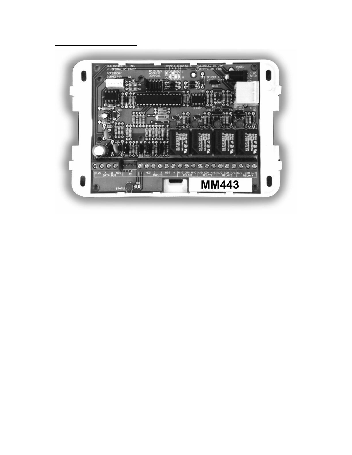
Magic Module
ELK-MM443 - Field Programmable Controller
Elk Development Software
Covers Software Release Version 5.1 – 16384 bytes of program memory.
Note: MM443
Magic Modules were shipped with 16384 bytes of program memory as of August 1, 2000 .
$10.00
Note: Specifications and features may change without notice. All rights are reserved by Elk Products, Inc.
Dallas iButton is a trademark of Dallas Semiconductor Inc., Dallas, Texas
PO Box 100
3266 US Hwy. 70 West
Hildebran, NC 28637 USA
828/397-4200 FAX 828/397-4415
http://www.elkproducts.com Email: info@elkproducts.com
Elk Products, Inc 1 Magic Module Instructions, Rev. 5.3 L391
Page 2

Introduction
The Magic Module family of low cost field programmable controller modules offers a unique controller and
data acquisition product line to markets not normally using such technology due to cost and complexity.
The ELK - MM220 is a two digital input two-relay output low cost programmable controller.
program the MM220.
computer. The code is then downloaded to the MM443 via a RS-485 data bus and programmed into re-programmable
Electrically Erasable Programmable Read Only Memory (EEProm memory). The MM220, a low cost stand-alone
version, is programmed from the MM443. Up to 31 MM443’s may be data bussed together and controlled from an
optional PC computer. Inputs and outputs may be read and controlled from the PC. The MM443 has a two way X-10
interface for transmitting commands to and receiving commands from X-10 Power Line Carrier Devices. Also an
optional interface is available for reading the Dallas iButton, and the 26 bit Wiegand Prox Card ID devices for
identification and access control applications.
Programs for the MM443 family may be written with an automatic Code Writer, which constructs programs
from a visual question list into a lower level Intermediate Code. The Intermediate Code, known as SIMPLE
like high level language that compiles the Intermediate Code into code byte’s that the micro processor reads out of
reprogrammable EEProm memory and executes the code through a built in operating system. The latest updates to
the Elk Product’s Magic Module Development Software are available at: www.elkproducts.com.
The Savoy MM220S & MM443S are available using the Savoy Automation “Cyberhouse” home automation
graphical software development system. Cyberhouse enables the user to either use the Magic Module system
standalone or connected to a PC for whole house and advanced network control. Savoy software to program the
Magic Module is available on the CD that accompanies the MK400S Development Kit. Additional Savoy Cyberhouse
information and software is available from www.savoyautomation.com/elk.
Components Available:
The ELK - MM443 is a four analog input, four relay output programmable controller that is also used to
The Magic Module is programmed by way of a code editor and software module simulator on a personal
, is a Basic-
• MK400 - Starter Development Kit for MM443S Magic Module.
• MK410 - Pre-programmed X-10 Transceiver. Four inputs, four relay outputs, sends and receives X-10.
• MK420 - Pre-programmed access control with 10 Dallas iButton’s.
• MM220 - 2 digital inputs, 2 relay outputs, stand-alone.
• MM443 - 4 analog inputs, 4 relay outputs, RS-485 data bus, X-10, Dallas iButton.
• MM443S - MM443 with Savoy Software.
• MM447 - MM443 Magic Module, MV-480 Voice Module, ML8 Caddx Interface; fits in Caddx Control Box.
• MV480 - 400 Channel Recordable Voice Annunciator - 480 seconds record time, RS-485 data bus.
• MB485 - RS-232 Serial Port to RS-485 Data Bus. Connects a PC to the RS-485 data bus.
• MK485 - Everything in the MK400S except the MM443S Magic Module
• MC100 - Real Time Clock - Plugs into the MM443 to give real time clock capability; Includes battery.
• MA100 - Dallas iButton Reader Interface and iButton Reader - Interfaces Dallas iButton to MM443.
Includes MA110 and MA190.
• MA101 - Package of 10 Dallas iButton’s.
• MA110 - iButton Reader and stainless steel faceplate.
• MA190 - iButton Reader Interface and cord.
• MT100 - Magic Module Remote Temperature Probe.
• MA290 -26 bit Wiegand Reader Interface for prox cards, with cord to Magic Module MM443.
• ML8 - Caddx Security Control Data Bus Interface
• 930 - Door Bell Interface, Telephone Ring Interface to the Magic Module and other automation
equipment.
Elk Products, Inc 2 Magic Module Instructions, Rev. 5.3 L391
Page 3

Table Of Contents
INTRODUCTION ............................................................................................................................................ 2
MAGIC MODULE MM443.......................................................................................................................................................................5
MM443 FEATURES ...................................................................................................................................... 5
MM443 SPECIFICATIONS ............................................................................................................................. 5
MM443 DESCRIPTION.................................................................................................................................. 6
MM443 HOOKUP DIAGRAM......................................................................................................................... 7
MM443 MAGIC MODULE INPUT HOOKUP OPTIONS SCHEMATIC ................................................................. 7
MM443 MAGIC MODULE LAYOUT .............................................................................................................. 8
MV120 (32 CHANNELS) & MV480 (400 CHANNELS) RECORDABLE VOICE ANNUNCIATORS.................... 10
Features ................................................................................................................................................. 10
Specifications......................................................................................................................................... 10
Hookup................................................................................................................................................... 10
MV120 / MV480 PC Board Layout.ELK-129 Hookup ......................................................................... 11
ELK-129 Hookup................................................................................................................................... 12
ML8 – MAGIC MODULE TO CADDX NX8 FAMILY DATA BUS INTERFACE ........................................................................13
ML8 HOOKUP 1 ......................................................................................................................................... 14
MAGIC MODULE CODE DEVELOPMENT PROGRAMS..............................................................................................................15
PC SYSTEM REQUIREMENTS:..................................................................................................................... 15
MAIN MENU............................................................................................................................................... 16
APPLICATION WRITER –....................................................................................................................................................18
General Tab........................................................................................................................................... 18
Scenes Tab ............................................................................................................................................. 18
Dusk and Dawn Settings Tab................................................................................................................. 20
Activated Inputs Tab .............................................................................................................................. 21
X-10 Click Buttons –.............................................................................................................................. 22
Relay Click Buttons –............................................................................................................................. 22
Scene Click Buttons –............................................................................................................................. 22
Voice Channels – ................................................................................................................................... 22
De-Activated Inputs Tab ........................................................................................................................ 23
Receive X-10 Tab................................................................................................................................... 23
Exception Annunciation......................................................................................................................... 24
Settings / Build Tab................................................................................................................................ 25
CODE EDITOR............................................................................................................................... 29
WRITING CODE .......................................................................................................................................... 30
Right Mouse Click (in Code Editor program area)............................................................................. 31
Event Programming Description........................................................................................................... 32
CODE WRITER............................................................................................................................................ 33
Input Event............................................................................................................................................. 34
Timer Event............................................................................................................................................ 35
X-10 Receive Event ................................................................................................................................ 36
Data Bus Receive Event......................................................................................................................... 37
Dallas iButton Reader or 26 Bit Wiegand Reader (Prox Card)............................................................ 38
X-10 Transmit ........................................................................................................................................ 39
Data Bus Transmit................................................................................................................................. 41
Real Time Clock (RTC) Event................................................................................................................ 43
ASCII Text String Transmission............................................................................................................. 44
File - Drop Down Menu in Code Editor................................................................................................ 45
Edit - Drop Down Menu in Code Editor................................................................................................ 45
Elk Products, Inc 3 Magic Module Instructions, Rev. 5.3 L391
Page 4

Window - Drop Down Menu in Code Editor ......................................................................................... 45
SIMULATOR - DEBUGGER..................................................................................................................................................47
Simulation Screen .................................................................................................................................. 47
Simulate Registers.................................................................................................................................. 48
Program Control.................................................................................................................................... 49
TRANSMIT/REMOTE CONTROL......................................................................................................................................50
Setup....................................................................................................................................................... 50
Transmit Screen ..................................................................................................................................... 51
Disassembly of Magic Module Code ..................................................................................................... 54
VOICE PLAY/RECORD SCREEN - .....................................................................................................................................55
MV120 (MV480) VOICE PLAYER/RECORDER - TYPE 4............................................................................. 55
WIZARD -.................................................................................................................................................................................57
SIMPLE PROGRAMMING LANGUAGE ........................................................................................................ 58
SIMPLE Intermediate Code Command Summary.................................................................................. 63
DATA BUS PROTOCOL................................................................................................................................67
ML8 CADDX TO MAGIC MODULE DATA BUS CONVERTER....................................................................................................68
CADDX NX8 FAMILY CONTROLS TO ML8 MAGIC MODULE INTERFACE.................................................... 68
COMMUNICATOR ACTIVATION................................................................................................................... 74
EventType............................................................................................................................................... 74
Contact ID Communicator Activation:.................................................................................................. 75
PhoneSelector........................................................................................................................................ 75
ContactIDCodes..................................................................................................................................... 75
SIA Format Communicator Activation:................................................................................................. 77
SIA Transmission Codes ........................................................................................................................ 77
Real Time Clock:.................................................................................................................................... 80
MM220 - MAGIC MODULE.................................................................................................................................................................81
MM220 FEATURES .................................................................................................................................... 81
MM220 SPECIFICATIONS ........................................................................................................................... 81
MM220 DESCRIPTION................................................................................................................................81
MM220 INPUT SCHEMATIC........................................................................................................................ 82
MM220 COMPONENT BOARD LAYOUT...................................................................................................... 82
EXAMPLE PROGRAMMING...............................................................................................................................................................83
TRAINER1 EXAMPLE PROGRAM ................................................................................................................. 83
TRAINER2 EXAMPLE PROGRAM ................................................................................................................. 84
Example Program “Trainer2”............................................................................................................... 88
FIVE YEAR LIMITED WARRANTY...................................................................................ERROR! BOOKMARK NOT DEFINED.
ADDITIONAL PRODUCTS.................................................................................................... ERROR! BOOKMARK NOT DEFINED.
Elk Products, Inc 4 Magic Module Instructions, Rev. 5.3 L391
Page 5
Magic Module MM443
MM443 Features
• Four analog or digital inputs
• Four relay outputs (two relay outputs may be jumper programmed for transistor open collector output at
100 milliamps max.)
• 16384 program bytes using SIMPLE programming language
• Four (4) Counters, range 0 to 255
• Four (4) Timers, range 1/10 second to over 255 hours
• Networked to optional PC and up to 31 other Magic Module’s through a RS-485 data bus.
• X-10 Power Line Carrier Interface. PL513, PSC04 (Transmit Only), or TW523, PSC05 (Two Way).
Analog transmission Magic Module to Magic Module and Preset Dim Commands.
• Dallas iButton Reader with optional MA100 or MA290 interface, or 26 bit Wiegand Prox Card Reader
with MA200 interface.
• Automatic Code Writer code development
• Programs the MM220 (two input, two relay output)
• Emulates MM220 for code development
• 130 SIMPLE Language Instructions
• Program stored in non-volatile EEProm memory
• Plastic white ABS enclosure with cover. 6.5 in. X 4 3/8 in. Mounts to single or double gang electrical
box. Optional DIN Rail Mounting. PCB mounts into 4 inch SnapTrack.
MM443 Specifications
• Magic Module RS-485 Data Bus Type 3
• Operating Voltage - 9.6 to 15 Volts DC
• Operating Current - 10 mA. Nominal, 130 mA. Maximum
• Operating Temperature - 32F to 122F (0C to 50C)
• Environment - Indoor non-condensing
• 4 - Analog inputs - 0 to 13.6 volts, with jumper programmable 2k pull up resistor to 12 V, or 2k pull down
resistor to ground. May be left floating. Software programmable hi and lo threshold levels per input makes it
easy to setup end-of-line resistor circuits.
• Input impedance (floating input) - 100K ohms
Elk Products, Inc 5 Magic Module Instructions, Rev. 5.3 L391
Page 6

• Four (4) Outputs - Four Relays - 12 Amps at 120VAC or 28VDC; 12 Amps at 240VAC general purpose; 7
Amps at 277VAC general purpose; ¼ hp at 120VAC; Two relay outputs may be configured as open collector
transistor outputs - 100 mA. Maximum.
• X-10 Interface - PL513, PSC04 or TW523, PSC05 (jumper selectable) - 4 wire RJ-11 telephone style female
connector on PCB
• Auxiliary Programming Connector J1 - 5 pin Methode style male connector (interfaces to cable Elk Part #
WO11A), .1” spacing, to MM220
• RS-485 Data Bus - up to 32 different device loads. Maximum length - 4000 feet
• Optional Real Time Clock (Elk Part # ELK-MC100)
MM443 Description
Usage - MM443 may be used as a stand alone field programmable controller in a vast array of applications
from timers, door controllers, simple process controllers, multiple zone security controls, etc. or as a networked
controller with up to 31 other modules connected on a common RS-485 data bus.
Inputs - Four analog or digital inputs with programmable low and high level switching thresholds accepting
input voltages directly up to 13.6 volts DC. Higher voltages can be used by using resistors on the input as a voltage
divider. Each input is jumper programmable for a 2K ohm input resistor pulled to 12VDC, ground, or no resistor input
voltage bias. The input loop response time may be adjusted with the set INxFilter command in 1/10-second
increments from 100 milliseconds to 25.5 seconds.
Outputs - Four form C relay outputs with contacts rated at up to 12 amps. Two relay outputs are jumper
programmable (JP11 & JP12) to switch the output through an open collector NPN transistor (100 ma maximum)
instead of the relay for higher speed applications such as flashing LED’s where the click of the relay is not desired.
Timers - Four timers ranging from 100 milliseconds to over 255 hours. Each timer is set in the program and
automatically counts down to zero. An if statement checks for the timer to be equal to zero (= 0) or not equal to zero
(not= 0) where the program will jump to a new statement.
Counters - Four counters with a range from 0 to 255 counts can be set, incremented, or decremented by the
program. An if compares the counter value with a variable value for =, not =, >=, or <, where the program will jump to
a new statement.
X-10 Powerline Interface - Connects to a X-10 PL513, PSC04 for transmit only or TW-523, PSC05 for
transmit and receive through a four conductor RJ-11 telephone style cable. Jumper JP10 selects between the PL-513,
PSC04 (one way) or the TW-523, PSC05 (two way) interface. The UVAL (unit value) and FVAL (function value) is set
when a X-10 transmission is received and matches the X-10 House Code (RHOUSE). The RHouse Code may be
different for each Magic Module on the Data Bus.
RS-485 Data Bus - The PC may send control commands to outputs and request status from the inputs on the
MM443. The modules may send commands and status requests to other magic modules as needed by the program.
Example: Module 1 will turn on its relay output 1 (Light switch) when Module 2’s input 1 (motion detector) is high.
Module 1 may also send an X-10 “Lights On” command to all X-10 modules to turn on lights. The combinations are
endless!
Excellent articles are available from National Semiconductor’s Website on wiring the RS-485 data bus at:
www.national.com/an/AN/AN-979.pdf
www.national.com/an/AN-1057.pdf
Programming - MM443 connects to a PC by way of the RS-485 data bus. The program is transferred from
the PC to the MM443 using the PC’s serial port and a RS-232 to an RS-485 converter box (ELK Part # MB485). Once
programmed, the Magic module may be disconnected from the data bus or the PC may be turned off. Two softwareprogramming interfaces are available: The SIMPLE programming language from ELK Products, Inc. (Basic Language
type programming), and the Savoy Cyberhouse Programming Language (Graphical Rules type programming).
Reset - In the event that a defective program has been loaded into the MM443 memory and the data bus can
no longer be accessed for reprogramming, the module’s program memory can be cleared and reset by shorting the
solder pads located at “TP1” and powering up the module. If TP1 remains shorted upon power up, MM443 will enter a
factory test mode. The factory test mode enables testing of the module. TP1’s short must be cleared for the input
loops to function. If any input (1 thru 4) goes to a high state the corresponding relay (1 thru 4 ) will activate. If TP1 is
shorted while the program is running, the module will be placed into the “STOP” mode and program execution will
cease. Data Bus response will continue.
Elk Products, Inc 6 Magic Module Instructions, Rev. 5.3 L391
Page 7
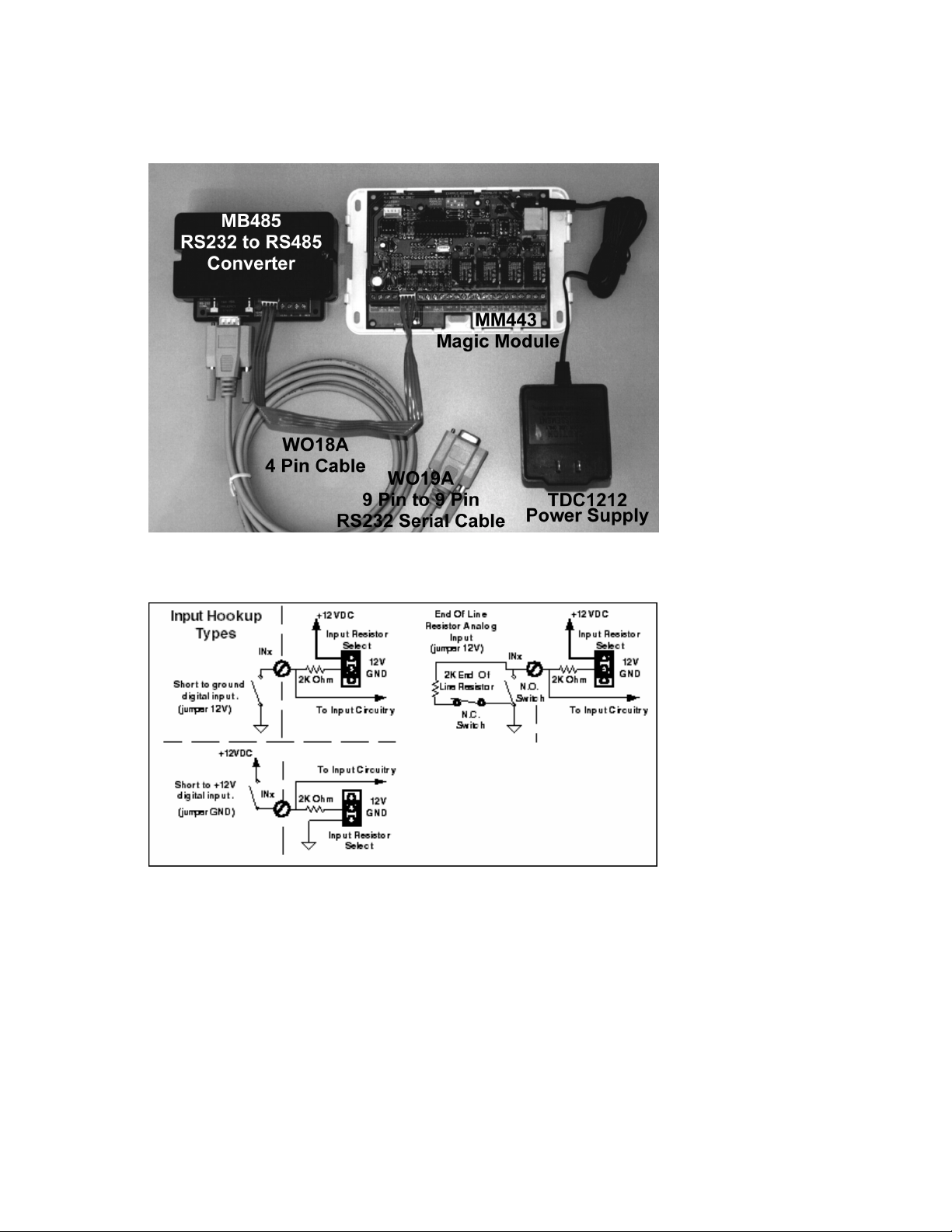
MM443 Hookup Diagram
MK400(S) Magic Module Development Kit Hookup
MM443 Magic Module Input Hookup Options Schematic
The inputs may be used as:
1. Normally Open Short to ground. Set JP1 thru JP4, according to the input, to the “+12V” pull up setting.
2. Normally Open Short to +12VDC. Set JP1 thru JP4 to the “GND” pull down setting.
3. End Of Line Resistor (EOLR) at 2000 ohms with Normally Open contacts across the resistor and/or
Normally Closed contacts in series with the resistor. Set JP1 thru JP4 to the “+12V” pull up setting.
4. Analog Voltage Input between 0 to 13 VDC. Remove the JP1 thru JP4 jumper. Use the if Inx <= value
to select what to do next in the program according to the input voltage level.
Note: A well-regulated power supply is required if reading analog input levels.
Elk Products, Inc 7 Magic Module Instructions, Rev. 5.3 L391
Page 8
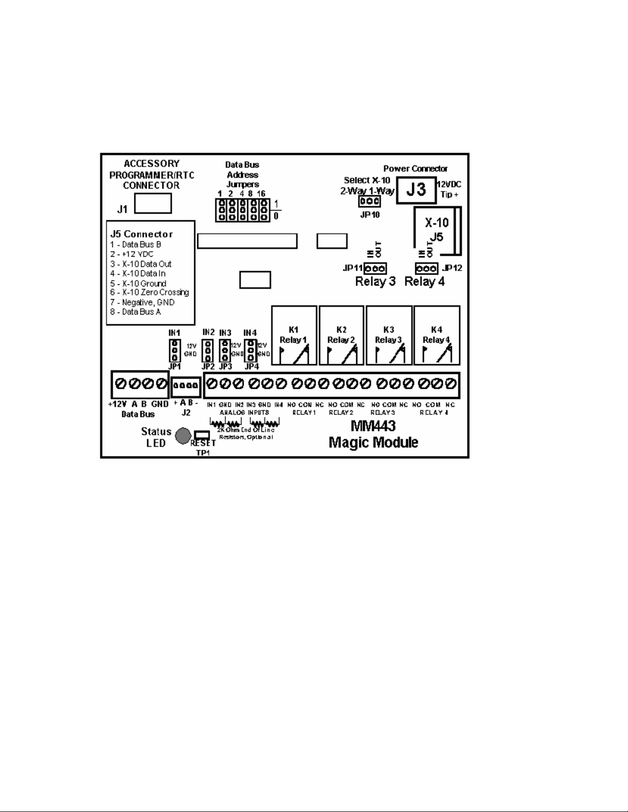
MM443 Magic Module Layout
+12 VDC may be supplied at four (4) locations on the MM443 Magic Module PC Board:
1. RS-485 Data Bus Terminals 1 and 4.
2. RS-485 Data Bus Jumper Header J2, Pins 1 and 4.
3. J-5 Eight-Pin Telco Type Connector, Pins 2 and 7.
4. J3 Power Connector for plug in power supply, center +12VDC.
Terminal Description:
1. +12VDC, minimum 100 milliamps. Will vary according to equipment connected to the Magic Module.
2. Data Bus A - RS-485 data bus. All “A” terminals must be connected together when the data bus is in use.
3. Data Bus B - RS-485 data bus. All “B” terminals must be connected together when the data bus is in use.
4. Ground - Common ground or power supply negative terminal.
5. IN1 - Input 1 terminal.
6. Ground - Common ground or power supply negative terminal. Used as the return terminal for the Input.
7. IN2 - Input 2 terminal.
8. IN3 - Input 3 terminal.
9. Ground - Common ground or power supply negative terminal. Used as the return terminal for the Input.
10. IN4 - Input 4 terminal.
11. NO - Relay 1 Normally Open Contact.
12. COM - Relay 1 Common Contact.
13. NC - Relay 1 Normally Closed Contact.
14. NO - Relay 2 Normally Open Contact.
15. COM - Relay 2 Common Contact.
16. NC - Relay 2 Normally Closed Contact.
17. NO - Relay 3 Normally Open Contact.
18. COM - Relay 3 Common Contact.
19. NC - Relay 3 Normally Closed Contact.
20. COM - Relay 4 Common Contact.
21. NC - Relay 4 Normally Closed Contact.
Elk Products, Inc 8 Magic Module Instructions, Rev. 5.3 L391
Page 9

JP11 and JP12 select Relay 3 and Relay 4 contacts In and Out of circuit. If JP11 (Relay 3) or JP12 (Relay 4)
is set to “Out” then the COM relay contact will pull to ground by a 100 milliamp maximum current transistor. This can
be used for low current circuits such as LED’s or buzzers in which the clicking of the relay would be annoying.
Data Bus Address Jumpers:
Each Magic Module connected to the RS-485 data bus must have a unique address set on each Magic Module. This
address is set on the Magic Module PC Board with five (5) jumpers. The address is set with a binary code, each
jumper has a value:
Jumper 1 (left jumper) = 1
Jumper 2 = 2
Jumper 3 = 4
Jumper 4 = 8
Jumper 5 = 16
By placing the appropriate jumper(s) in the upper or 1 position, the address setting may be set by adding up the
jumper values.
Example: Set data bus address 5.
Jumper 1 and jumper 3 will be placed into the “1” position. Add up the value: 1 + 4 = 5.
Set data bus address 17.
Jumper 1 and jumper 5 is placed into the “1” position. Add up the value: 1 + 16 = 17.
Note: After changing the data bus address jumper settings, the power
must be turned off and turned back on before the new jumper settings
will take effect.
Elk Products, Inc 9 Magic Module Instructions, Rev. 5.3 L391
Page 10

MV120 (32 Channel) & MV480 (400 Channel) Recordable Voice
Annunciators
The MV480 is a MV120 with extended record time of 480 seconds and a total of 400 channels. Each channel’s record
time is 1.2 seconds.
Features
• Controlled from the MM443 Magic Module or compatible controllers.
• 32 individually addressable message channels on MV120, 400 channels on MV480.
• 120 seconds maximum record time on MV120, 480 seconds on the MV480).
• Any message can be any length up to the maximum record time.
• 31 MV120 or MV480s may be networked on the Magic Module RS-485 Data Bus
• Built-in microphone or download a computer wave file using the ELK-129 computer interface.
• Record and playback controlled from a PC computer.
• Adjustable volume control.
• Output for direct connection to audio amplifiers.
• 24-Watt built-in audio amplifier.
• Two speaker connections
Specifications
• 10.25 to 15 Volts DC, well regulated. Note: Low cost plug in DC power supplies may not work due to AC hum
present on the power supply. Recommended: Elk-624 Power Supply with ELK-B1240 standby battery.
• Temperature 20 degrees F. to 122 degrees F, non-condensing. Contact the factory if to be used in extended
temperature environments.
• Maximum current draw at full volume: 1.25 amps. Adjust volume for desired maximum current draw.
• Maximum output speaker load 4 ohms.
• RS-485, simplex data bus. Two Data, two power, +12VDC & NEG.
• Type 4 Magic Module, Addressed from 1 to 31. Address 0 = global non-responding address.
Hookup
Power Supply – The MV120 (MV480) may be power from any of four different locations on the printed circuit board.
1. J3 Power Connector – Plug in a well regulated +12VDC power supply into the connector. The center
conductor is +12V. 2.1mm ID X 5.5mm OD Female plug on the power supply.
2. Terminals 1 & 4 – Terminal 1 is +12VDC and terminal 4 is Negative.
3. Connector J2 – Pin 4 is +12VDC and pin 1 is Negative.
4. Connector J1 – Elk-129 Computer audio programming connector, Pin 4 is Negative. Connect one of the
AC Transformer inputs on the ELK-129 to terminal 1 on the MV120 (MV480) to provide +12VDC to the
internal circuitry on the ELK-129.
Data Bus Connection - The RS-485 Data Bus may be connected in two locations:
1. Terminals 2 & 3 – Terminal 2 is “A” side of the data bus. Terminal 3 is “B” side of the data bus.
2. Connector J2 – Pin 3 is “A” side of the data bus. Pin 2 is “B” side of the data bus.
Note: Data Bus “A” must connect to Data Bus “A” on other modules and Data Bus “B” must connect
to Data Bus “B” on other modules for proper operation of the Data Bus.
Speaker Connection – Two 8 ohm speaker connections are available at Terminals W1 & W2 SPKR1 and W1& W2
SPKR2. When an 8-ohm speaker is connected to both terminals, an effective 4-ohm speaker load is placed on the
amplifier. The speakers may also be wired in series to add more speakers to the system. To connect the MV120
(MV480) to a low level line input going into another audio amplifier, turn the volume all the way down, then turn it up until
the audio level into the other amplifier is satisfactory.
Note: Maximum speaker load on the audio amplifier is 4 ohms.
Jumper Selection – There are two sets of jumpers that should be configured before use of the MV120 (MV480).
Elk Products, Inc 10 Magic Module Instructions, Rev. 5.3 L391
Page 11
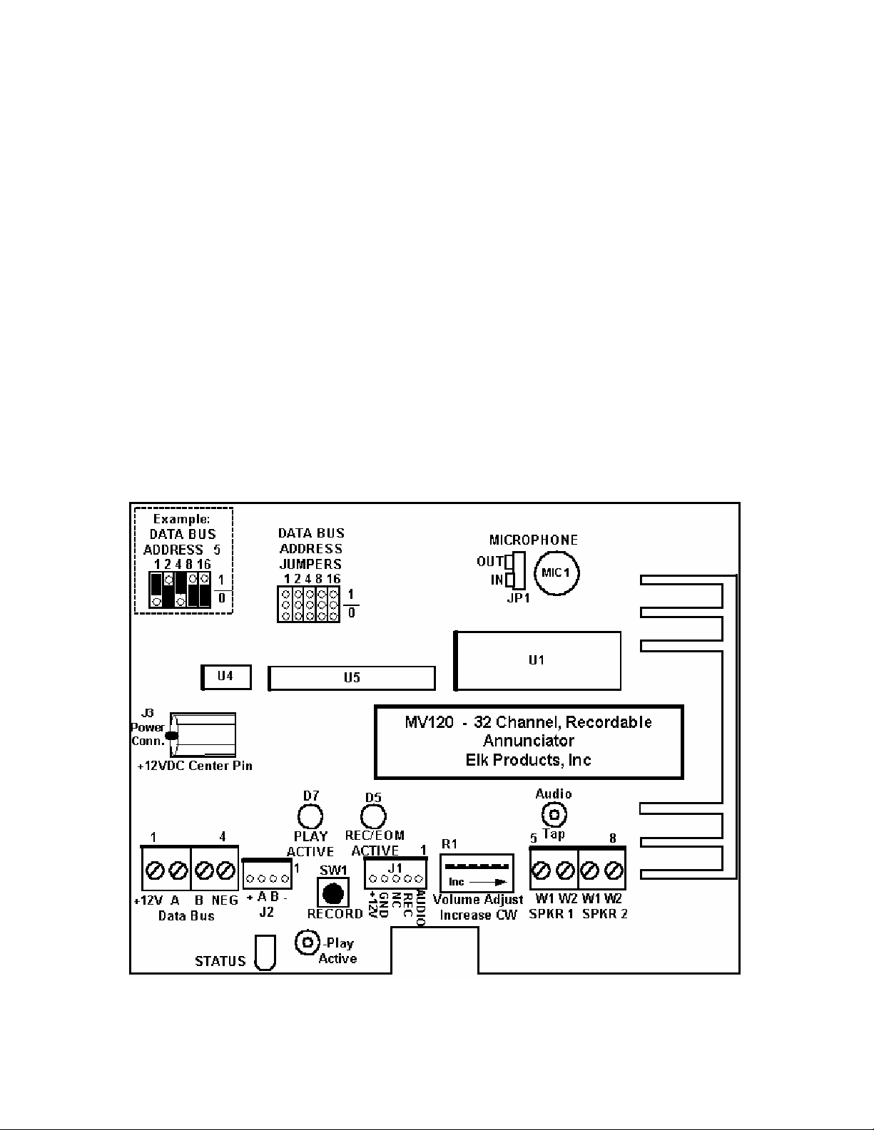
1. MIC, JP1 – Microphone enable – If the on board microphone is to be used to record messages; the
jumper at JP1 must be set to the “IN” position (IN Circuit). If the ELK-129 Computer Interface is to be
used to record messages, the jumper at JP1 should be in the “OUT” position (OUT of Circuit).
2. Data Bus Address Jumpers – Each voice module must be set to its own individual data bus address.
The address is set with 5 jumpers. There are two settings, 0 or 1, for each jumper. When the jumper is
in the 0 position, its value is equal to 0. When it is set to the 1 position, its value is shown above the
jumper: 1, 2, 4, 8, 16. Add up the jumpers in the 1 position to see the data bus address setting.
Example: jumper 1 is set to the 1 position; jumper 4 is set to the 1 position. Add the values: 1 + 4 = 5
the data bus address = 5. If a jumper is missing, its value will be 0.
Play Active SolderPad – The solder connection is pulled to ground by a transistor when the MV120 (MV480) is
playing a message. It may be connected to an ELK-924 Relay to trigger other equipment. The maximum current draw
at the solderpad is 50 milliamps.
Audio Tap SolderPad – A low level audio signal may be taken to another audio amplifier from this solder pad.
RECORD Button – When the MV120 (MV480) has been given a record command from the computer, the record
button should be pressed and held during the recording session. Speak clearly into the on board microphone. When
the button is released, the message just recorded will be played. If the record button is not pressed within 45
seconds, the MV120 will return to normal operating mode and cancel the record request. Pressing the RECORD
Button without a record command issued from the computer will play the last message recorded or the first message if
no recording has taken place.
Status LED - blinking – The status LED blinks when the MV120 is in normal operation.
On continuous – The status LED will be ON continuous when a record command is received from
the PC computer. The status LED will return to blinking within 45 seconds if the record button is not
pressed on the MV120 (MV480).
MV120 / MV480 PC Board Layout.
Elk Products, Inc 11 Magic Module Instructions, Rev. 5.3 L391
Page 12
ELK-129 Hookup
The ELK-129 Computer Interface connects a computer sound card to the MV120 (MV480) Voice Module so that
WAV files or other audio files may be downloaded to the MV120 (MV480). See the ELK-129 instructions for
further information.
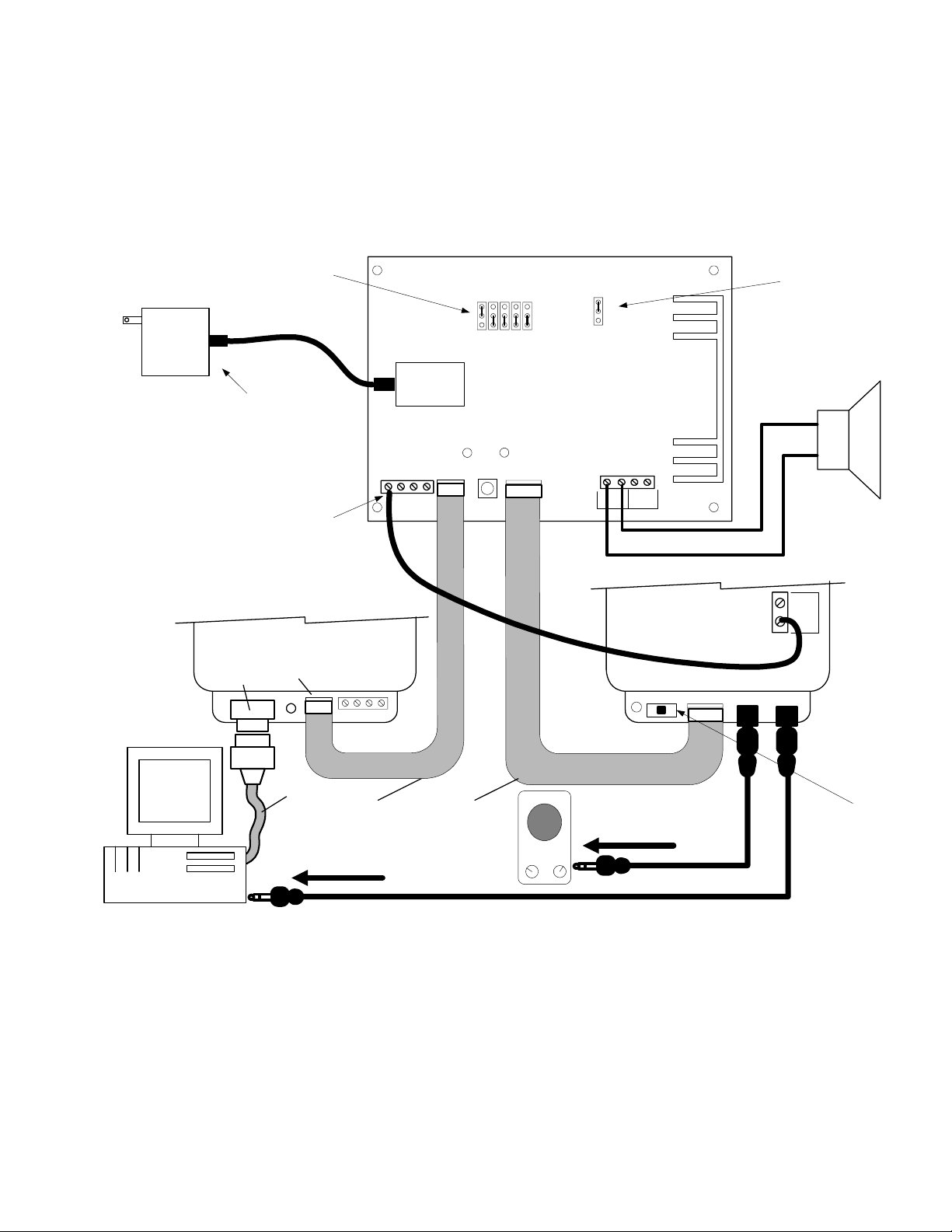
Recording Hookup for MV120/MV480 to ELK-129
SET TO THE
CORRECT
ADDRESS
+12 VOLT
DC PLUG IN
POWER
SUPPLY
USE A FILTERED AND REGULATED
12 VDC @ 1.2A POWER SUPPLY
(ELK-T1212 RECOMMENDED)
TO POWER THE ELK-129, CONNECT
FROM THE MV120 "+" TERMINAL TO
THE ELK-129 12VAC INPUT AS SHOWN
(DO NOT CONNECT A 12VAC
TRANSFORMER TO THE ELK-129)
THE MB485 IS POWERED FROM THE MV120
THROUGH THE 4 PIN RIBBON CABLE
ELK-MB485
P1
RS-485 DATA BUS
CONNECTOR
RS-232 SERIAL
PORT CONNECTOR
ELK-MV120/MV480 VOICE MODULE
OUT
MIC
IN
POWER
124816
1
0
DATA BUS
ADDRESS
JUMPERS
MOVE "MIC"
JUMPER TO THE
"OUT" POSITION
8 OHM SPEAKER
J3
SW1
J2 J1
BA
-
+
W1 W2 W1 W2
SPKR2
SPKR1
12
VAC
INPUT
ELK-129
AUDIO OUT AUDIO INSW1 J1
-
+
BA
PC
9
PIN
SERIAL
CABLE
4 PIN
RIBBON
CABLE
5 PIN
RIBBON
CABLE
To Amplified
Speakers
SWITCH TURNED
OFF, LED STAYS
To Sound Card
Line Out
Elk Products, Inc 12 Magic Module Instructions, Rev. 5.3 L391
LEAVE THIS
ON WHEN
POWERED
Page 13

ML8 – Magic Module To Caddx NX8 Family Data Bus Interface
The ML8 Interface (ELK-ML8) connects to the data bus of the Caddx NX Control using only 2 wires. Data received
from the control is mapped to 16 collection flags. Changes to these flags are broadcasted over the Magic Module data
bus. In addition, 240 bits of data from the NX8 Control may be interrogated on demand by the Magic Module. In order to
program the 16 collection flags or develop a Home Control or Automation application, a Magic Module Programmers Kit
(ELK-MK485) is needed which includes the Elk Application Writer. There is also a ready to install kit "Home Control Lite"
available which includes a programmed Magic Module, ML8 Interface, plus a Magic Voice (ELK-MV480) 400 channel
recordable voice annunciator.
See ML8 Hookup on next page.
INSTALLATION
Step 1. Disconnect all power to the Caddx NX Security Control and the ELK Magic Module.
Mount the ML8 Interface using the enclosed self-adhesive foam tape or two of the special NX enclosure slide
Step 2.
Step 3. Connect the ML8 Interface, Caddx NX Control, and Magic Module as per ML8 Hookup on next page.
Step 4. After all wiring connections are complete, apply power to the NX Security Control and Magic Module.
Step 5. Use the Magic Module "Code Writer" or "Application Writer" software to setup the 16 collection flags and
LEDs
RCV = Blinks when the NX Control is transmitting information to the ML8 Interface
STATUS = Blinks slowly when the Control Keypad data bus is operational.
PWR = On when the ML8 Interface is receiving Power.
rails available separately from Caddx.
NOTE: ML8 Hookup on next page shows no connection to terminal +V on the ML8 Interface. The
Magic Module source is powering the unit. To power the ML8 Interface and/or Magic Module from the
Caddx NX, connect a wire from +V to the Caddx Keypad POS terminal. Be certain that the maximum
combined current draw including any keypads or auxiliary devices does not exceed the ratings
published with the control. The ML8 Interface and one Magic Module draw 55mA idle or 185mA with
all relays active. A Magic Voice Module will add an additional 70mA idle and up to 500mA when
active with 3/4 volume setting.
develop the desired operation program. The Software includes a manual and on-line help screens.
XMIT = Blinks when information is being transmitted to or received from a Magic Module
Elk Products, Inc 13 Magic Module Instructions, Rev. 5.3 L391
Page 14
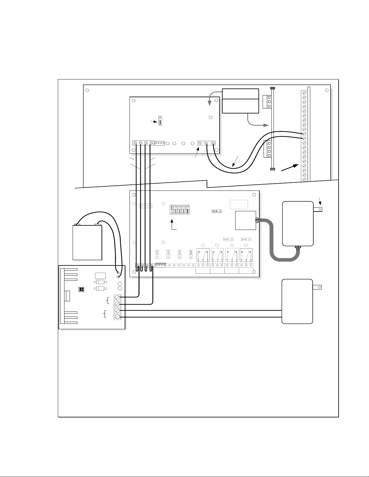
ML8 Hookup 1
*
CADDX NX4/6/8 ALARM CONTROL
RS-485 BUS
(4 WIRES)
+
*
BATTERY
-
ELK-1240
JP1 ON
JP2 OFF
Do Not Move Jumpers
JP1
JP2
DC OUTPUT
AC
TRANSFORMER
*
ELK-624 12V POWER SUPPLY
+
-
AC
AC
RED
GREEN
-
+
LEDS
LINK INTERFACE
ELK-ML8
Leave in the
NORMAL
Position
J1
BA
+
BATTERY
AC DC
Mount the ELK-ML8
Interface Here
Or
Mount using
Optional Rails Here
JP1 MODE
AUX
NORMAL
NEGB+12V A
RCV
XMIT
J1
BLACK
YELLOW
*
ELK-MM443 MAGIC MODULE
124816
JP2JP1
PWRSTATUS
See Step 3 for +V
Optional Hookup
DATA BUS
ADDRESS
JUMPERS
SET TO ADDRESS 1
JP4
JP3
D5
not used
DATANEG+V
SELECT X-10
2-WAY 1-WAY
K1
JP10
K2
TO
CADDX
KEYPAD BUS
(2 WIRES)
POWER
J3
X-10 and
DALLAS
Interface
RELAY 4
RELAY 3
IN OUT
K3
-
NOCOMNC
1-2
J2
NOCOMNC
4
3
-
RELAY 1
NOCOMNCNO COMNC
RELAY 2 RELAY 3
Items noted with * must be purchased separately
J5
IN OUT
K4
RELAY 4
DATA
NEG
+V
NEG
B DATA
A DATA
+12 VOLTS
CADDX NX ALARM
CONTROL BOARD
* X-10
POWERLINE
INTERFACE
MODEL:PSC05
*
Transformer
16.5 VAC
40 VA
ELK-TRG1640
TO AC POWER
RECEPTACLE
2 WAY
KP DATA
KP COM
KP POS
Required
only for
Applications
using X-10
Devices
Elk Products, Inc 14 Magic Module Instructions, Rev. 5.3 L391
Page 15

Magic Module Code Development Programs
PC System Requirements:
• Windows 95 or 98, minimum suggested Pentium 75 Mhz
•
16 meg Ram
•
50 meg Hard Drive Space
•
CD Drive for program installation
•
RS-232 Serial Port
•
Display 800 X 600 X 16 bit SVGA or greater
•
Mouse
•
Optional soundcard for wave file programming of the MV120 (MV480) with the ELK-129
There are two types of development software available:
Elk Products, Inc. Development Software
Written using a code editor and automatic Code Writer in a “Basic Language Like” structure called SIMPLE.
This programming environment is familiar to experienced programmers. The Elk version offers program
simulation and debug capabilities.
Savoy Automation, Inc. Development Software
Savoy Automation software offers standalone Magic Module applications or the Magic Module can be
connected to a PC server for advanced network and whole house home automation applications tying together
other equipment into a unified automation system.
Software Development Installation CD
Insert the ELK Software Development CD into your CD Drive and follow the directions. If the following screen
does not show up, from the Explorer window select the CD Drive, then the autorun.exe program on the CD.
Elk Products, Inc 15 Magic Module Instructions, Rev. 5.3 L391
Page 16
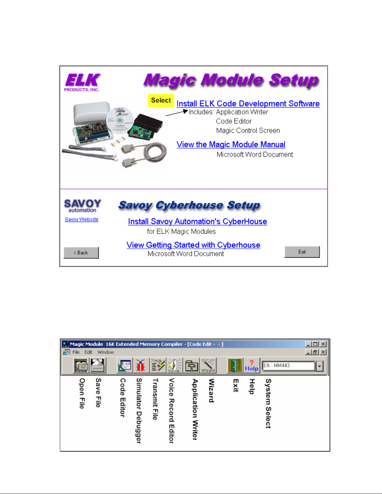
Both versions of software are available on the CD that comes with the Magic Module MK443S Software Development
Kit.
CD Startup Screen
Main Menu
After starting the Magic Module Code Development Software, the Main Menu will appear. From this window you may
choose which program to run:
Elk Products, Inc 16 Magic Module Instructions, Rev. 5.3 L391
Page 17
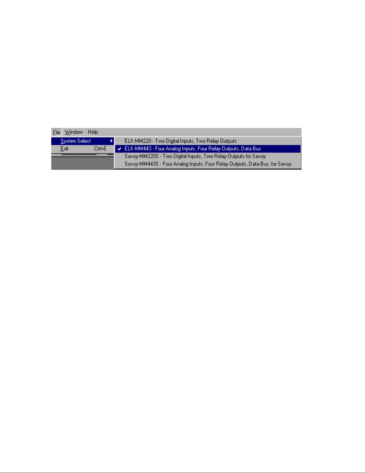
System Select:
Four systems are available to select:
1. ELK-MM220 Two digital input, two relay outputs, stand alone.
2. ELK-MM443 Four analog inputs, four relay outputs, data bus, X-10, Dallas iButton capability.
3. Savoy-MM220S Two digital input, two relay outputs, stand alone for Savoy’s Cyberhouse software.
4. Savoy-MM443S Four analog inputs, four relay outputs, data bus, X-10, Dallas iButton capability for Savoy
Cyberhouse software.
File / System Select, then the system selection. Note: The initial program screen must be displayed with no
Select
other screens open to execute the “System Select” function.
Elk Products, Inc 17 Magic Module Instructions, Rev. 5.3 L391
Page 18
Application Writer –
The Application Writer is designed for
automation features of the MM443 Magic Module simply by clicking buttons on the Application Writer Screens. This
allows quick programming and customization of a very powerful and inexpensive home automation system.
The Application Writer may use the Caddx NX4, NX6, or NX8 Security Control as 16 inputs to the Magic Module by
using the ELK ML8 Caddx To Magic Module Data Bus Converter.
The Application Writer writes a Magic Module .src file from the buttons that the installer selects. Further
customization may be added with the
non-programmers to be able to program and utilize many of the home
Code Editor.
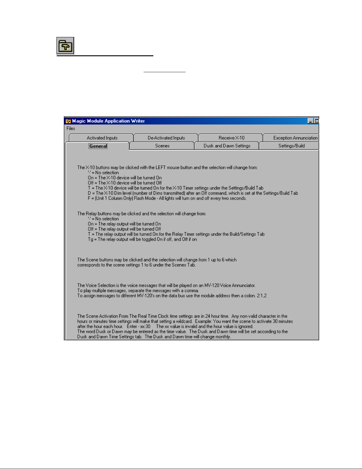
General Tab
The General Tab provides Help information on how to use the Application Writer.
Scenes Tab
Scenes may be described as lighting, relay, or voice setting that is triggered from an input or a time of day.
Example 1: Define Scene 1 as the Morning Scene. The kitchen and bedroom lights turn on. The coffee maker turns
on. The HVAC changes to the morning mode and a voice command is triggered to tell everyone to get out of the bed.
Elk Products, Inc 18 Magic Module Instructions, Rev. 5.3 L391
Page 19
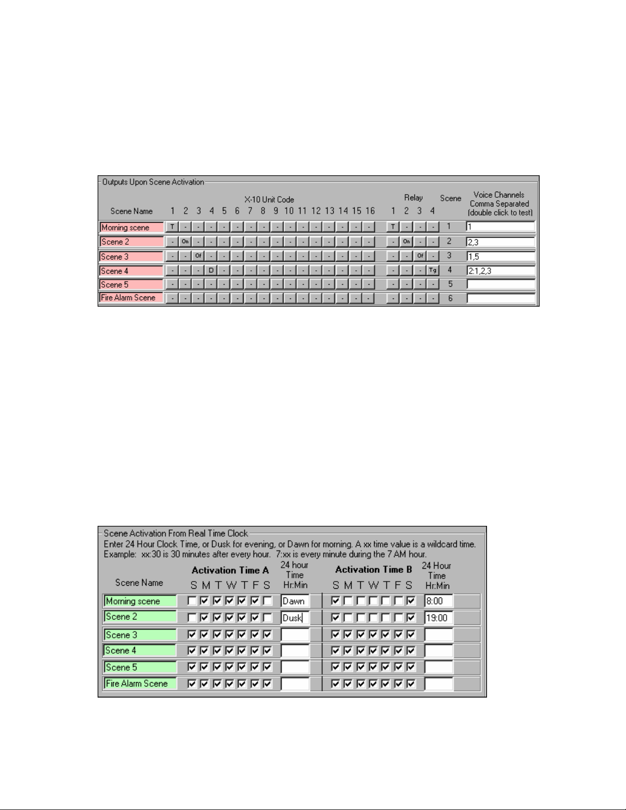
Example 2: Define Scene 6 as the Fire Alarm Scene. When triggered from the Caddx Security Control. All the lights
turn on. The HVAC turns off. A repeating voice message tells everyone to leave the premise and assemble in the
front of the house. The message is recorded with the mothers voice to calm the children.
The Scene Names may be edited like the “Input” names.
The Voice Channels and the Click Buttons for the X-10 Unit Codes and Relays function the same as
described on the
“Activated Input” Tab.
Scene Activation From Real Time Clock –
If the Caddx Security Control is used, the real time clock time comes from the Caddx Control. Otherwise, install an
ELK MC-100 Real Time Clock Module onto the MM443 Magic Module for the real time clock operation.
The 6 Scenes may be triggered from the real time clock. Two time settings are available for each Scene:
Activation Time A and Activation Time B. Each Activation Time has the option of selecting which day during the
week that the scene will activate. If the Day Of The Week selection box is checked, the real time clock will activate the
scene on that day when the time of day is reached.
Note: All times are in 24 hour time: 00:00 is midnight, 3 PM is 15:00. The scene is checked every minute for all the
times that could set the scene.
A wildcard time is available for special activations by using “xx” as the hour or minute time.
Example 1: “xx:45” will activate the scene 45 minutes past every hour.
Example 2: “18:xx” will activate the scene every minute during the 6 PM hour.
Example 3: “xx:xx” will activate the scene every minute.
Example 4: “Dusk” and “Dawn” will reference the settings in the “Dusk and Dawn Settings” Tab.
Elk Products, Inc 19 Magic Module Instructions, Rev. 5.3 L391
Page 20
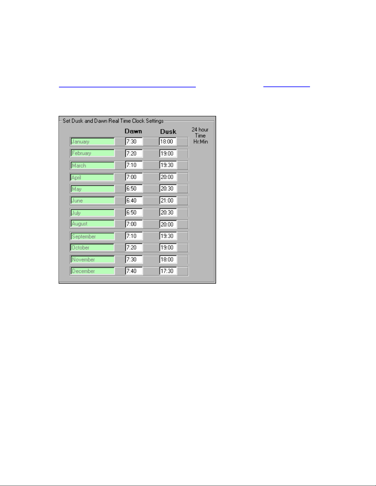
Dusk and Dawn Settings Tab
To turn items on and off at dusk and dawn, the time settings are adjusted on a monthly basis. Insure that the
dusk and dawn time setting for your area are correct. Remember day light savings time corrections. The time is
always set in a 24-hour format. Example: 5 pm = 17:00.
Dusk and Dawn settings may be downloaded from the Internet at:
http://www.mindspring.com/~cavu/sunset.html or referenced through http://www.cavu.com/
These Dusk and Dawn time settings are used in the
section under the
Scenes Tab.
Scene Activation From Real Time Clock settings
Elk Products, Inc 20 Magic Module Instructions, Rev. 5.3 L391
Page 21
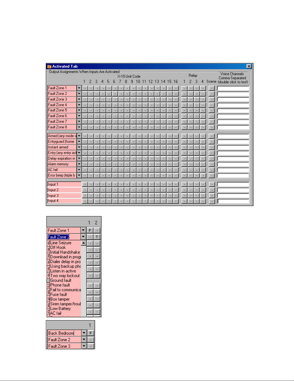
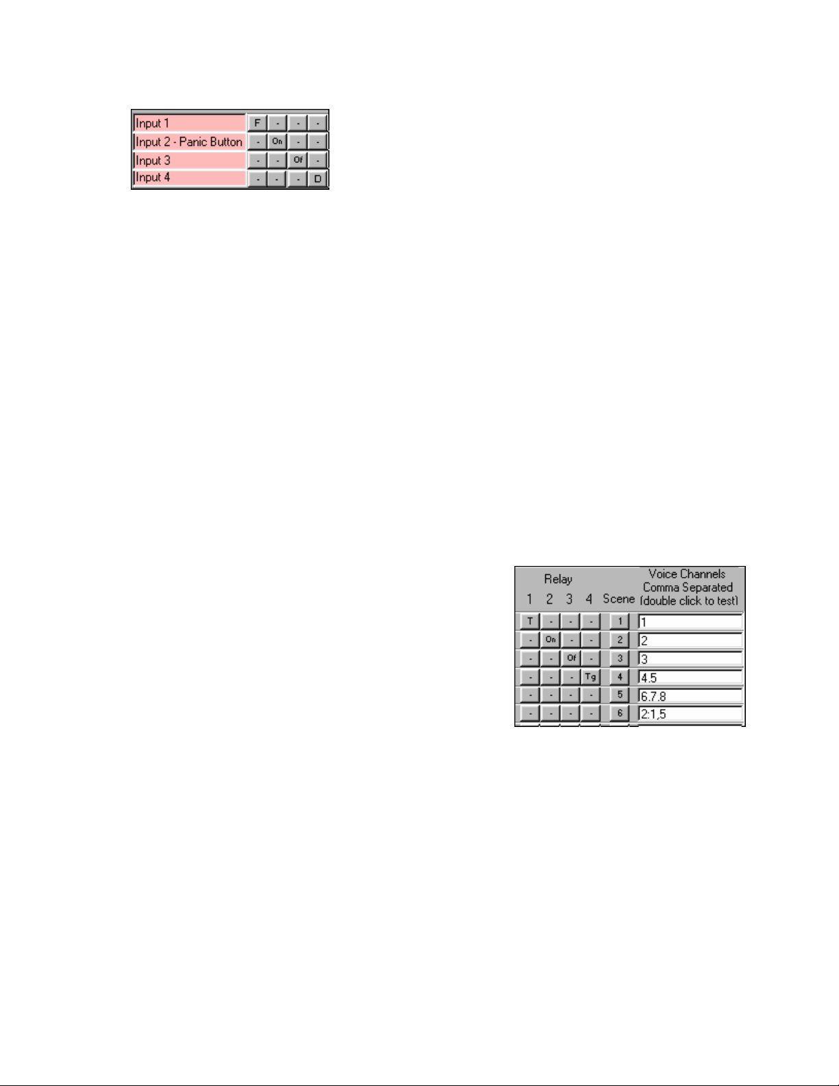
Activated Inputs Tab
Activated Inputs – What do you want the Magic Module to do when the input is triggered on or goes into an active
state? Up to 16 X-10 Unit Codes may be controlled with Flash, On, Off, Dim and Timed On, the four (4) relay outputs
on the Magic Module may be controlled, up to 6 Scenes may be controlled, and the MV120 Voice Annunciator may
speak multiple voice messages.
The first 16 positions in the left input column are the Caddx NX8, 6, or 4 Security
Control Inputs. The programmer can select from 240 different data inputs from
the Caddx Security Control in each of the 16 positions. Just click on the down
arrow to the right of each box and select the input desired. See the
Description Section for further explanation of the Caddx inputs
The input description may also be changed to help the programmer remember what
the input is used for. When the input descriptions under the Activated Inputs are
changed, then all the other input descriptions associated with that input would also be
changed
name will be displayed.
. If the cursor hovers over the input description, the original input
Caddx Input
.
Elk Products, Inc 21 Magic Module Instructions, Rev. 5.3 L391
Page 22
The four (4) analog inputs to the Magic Module are available at the bottom
left of the screen. Up to 16 X-10 Unit Codes may be controlled with Flash,
On, Off, Dim and Timed On, the four (4) relay outputs on the Magic Module
may be controlled, up to 6 Scenes may be controlled, and the MV120
Voice Annunciator may speak multiple voice messages. When the input
descriptions under the Activated Inputs are changed, then all the other
input descriptions associated with that input would also be changed.
Note: The Click Buttons for X-10, relays, scenes, and voice
annunciation operate the same on all screens
X-10 Click Buttons –
To select a function on the X-10 Unit Codes that correspond to an input, click the button with the mouse. The button
caption will change as follows:
“-” No selection. No code will be generated for that input and output.
1.
2. “T” – Turn the X-10 device on for the time setting under the “Settings/Build” Tab and “X-10 Timer Setting”.
The timer range is from two seconds to 255 hours.
command, so do not use a one second timer setting.
3. “On” – Turn the X-10 device on.
“Of” – Turn the X-10 device off.
4.
“D” – Dim the X-10 device. First the device is turned off, then the number of X-10 Dim commands that are
5.
set in the “Settings/Build” Tab and “X-10 Dim” setting are transmitted. Ten (10) Dims will go to half
brightness.
“F” – Available in the X-10 Unit 1 column only. All 16 X-10 Unit codes will turn the lights on and off every
6.
two seconds until an X-10 “Off” command is issued. This can be used when an alarm is tripped to alert the
neighbors or the police.
Note: It takes two seconds to send the X-10
Relay Click Buttons –
To select a relay output function on the Magic Module that corresponds to an input, click the button with the mouse.
The button caption will change as follows:
“-” No selection. No code will be generated for that input and
1.
output.
“T” – Turn the relay output on for the time setting under the
2.
“Settings/Build” Tab and “Relay Timer Setting”. The timer range
is 1/10 of a second to 255 hours
“On” – Turn the relay output on.
3.
“Of” – Turn the relay output off.
4.
5.
“Tg” – Toggle the relay’s on/off state. If the relay output is on,
turn it off. If the relay output is off, turn it on.
Scene Click Buttons –
To select a Scene that corresponds to an input, click the button with the mouse. The button caption will change from 1
to 6, which corresponds to Scenes 1 to 6 as described under the “Scenes” Tab.
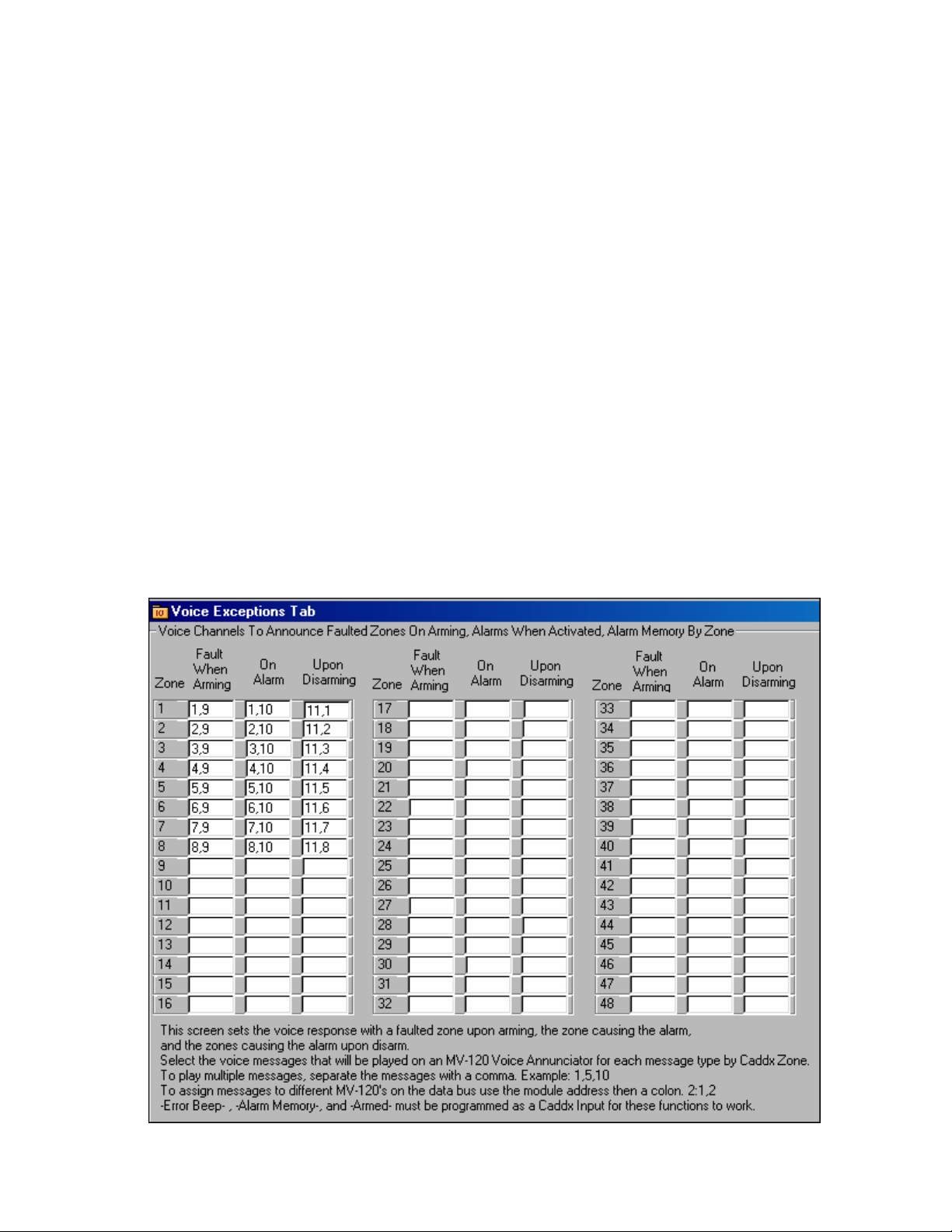
Voice Channels –
To select and speak a Voice Channel that corresponds to an input on the MV120 (MV480) Voice Annunciator that
connects to the Magic Module Data Bus, type in the voice channel (1 to 32 MV120, 1 to 240 MV480). If multiple voice
messages are to be concatenated together, separate them with commas.
Example: 1,2,3,4. By default the voice commands are sent out onto the data bus with a global address of “0”. This
will command all voice modules to say the same voice channels on each module. Should you want to direct the voice
command to a particular MV120 on the data bus, precede the voice commands with the MV120 (MV480)’s Data Bus
Address then a colon. Example: 2:4,5 this will command the MV120 with a data bus address 2 to say voice channels
4 and 5. Double clicking the voice channel text box will immediately send the voice channels to the MV-120 (MV480)
to test the voice messages.
Elk Products, Inc 22 Magic Module Instructions, Rev. 5.3 L391
Page 23

De-Activated Inputs Tab
De-Activated Inputs – What do you want the Magic Module to do when the input is restored to a normal or non-alarm
state? Up to 16 X-10 Unit Codes may be controlled with On, Off, Dim and Timed On, the four (4) relay outputs on the
Magic Module may be controlled, up to 6 Scenes may be controlled, and the MV120 (MV480) Voice Annunciator may
speak multiple voice messages.
Note: All Click Buttons work the same as the
Activated Inputs Tab.
Receive X-10 Tab
Up to 16 received X-10 signals from X-10 Unit Code 1 – 16 may be combined with any X-10 function code to
create a unique received code. When the unique X-10 Code is received other X-10 devices may be controlled, the
four relays may be controlled, Scenes may be triggered, and voice messages may be announced.
The click buttons all have the same operation as described in the
The received House Code is set under the
Code may be any one-house
code from “A” to “P”.
Settings/Build tab, Received House Code. The received House
Activated Inputs Tab.
Example above:
When X-10 Unit Code 1, Function On is received, turn on and time Unit 1 for the time set under the
Settings/Build tab. Turn on X-10 Unit 2, turn on relay 1 for the time set under the Settings/Build tab, turn on relay 2,
and speak voice channels 1 and 2 through the MV120 (MV480) Voice Annunciator.
When X-10 Unit Code 2, Function Off is received, turn off X-10 unit 3. When X-10 Unit Code 3, Function Dim
is received, Dim X-10 Unit Code 4.
Elk Products, Inc 23 Magic Module Instructions, Rev. 5.3 L391
Page 24
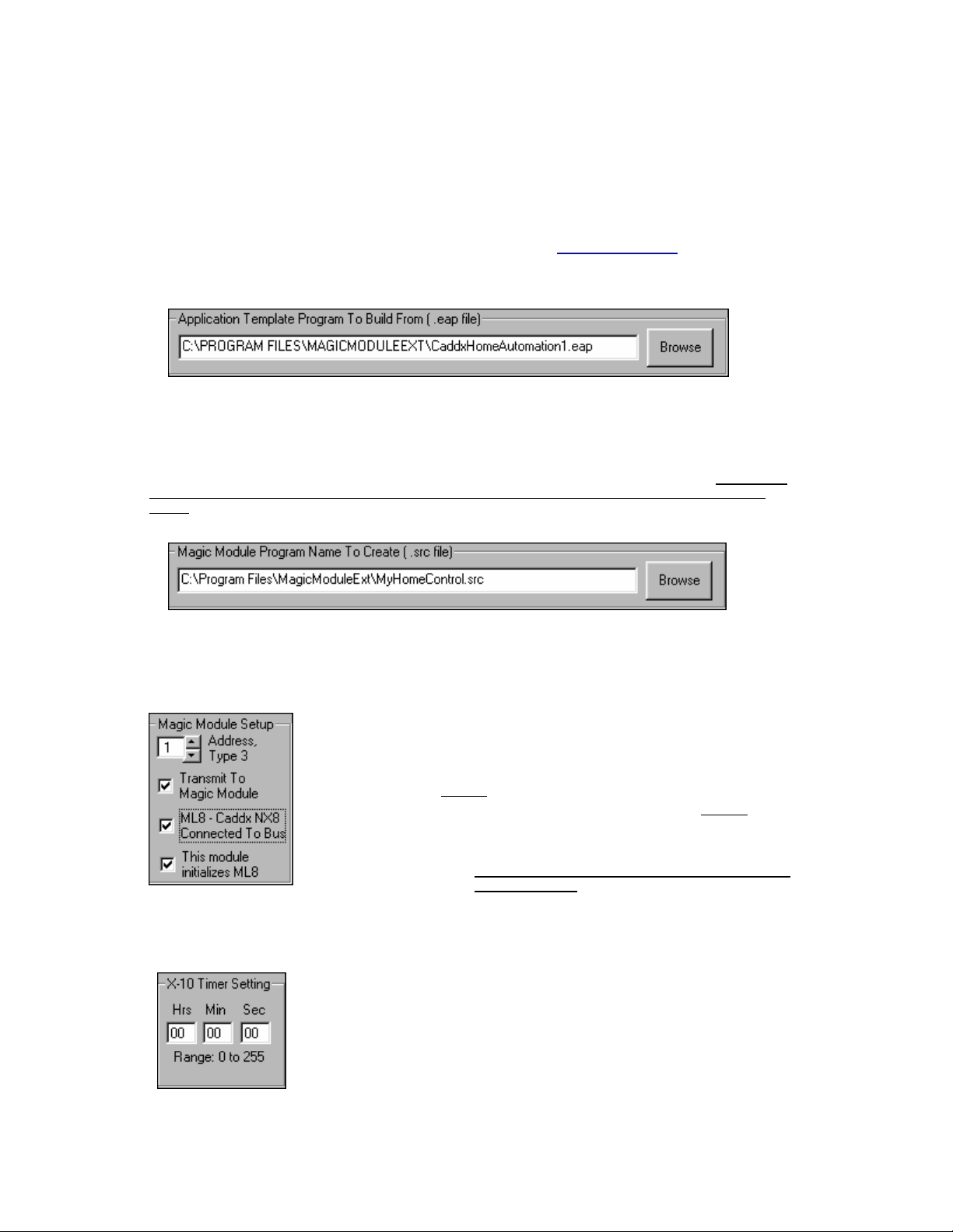
Exception Annunciation
categories:
Insert the Voice Channels to speak into the corresponding zone and annunciation type columns text box with
each voice channel separated by commas. The voice channel input range is from 1 to 32.
By default all voice transmissions are to a global address of “0”. To direct the voice transmission to a specific
MV120 Voice Module, enter the MV120’s data bus address followed by a colon (:) then the voice channel to speak:
2:1,2.
Channels are programmed using the
to the front door, so program channel 1 as “Front Door” and so forth through zone 8 describing each zone with a voice
message.
Program voice channel 9 as “is open”.
Program voice channel 10 as “triggered the alarm”.
Program voice channel 11 as “an alarm was caused by the”.
When the “front door” is open and arming the alarm is attempted, “front door is open” will be annunciated.
When the “front door” causes an alarm, “front door triggered the alarm” will be annunciated. Then upon
disarming the control, “an alarm was caused by the front door” will be annunciated.
Exception Voice annunciation by the ELK MV120 (MV480) may be programmed to speak in three (3)
Fault When Arming: Upon arming and one or more of the Caddx Security Control Zone
1.
2.
3.
Example below:
Program the MV-120 (MV480) voice channels 1 through 8 with the zone description. The Voice
inputs are violated or open. Make sure one of the Caddx Inputs on the
programmed as an
On Alarm: When the Caddx Security Control goes into alarm, the zone input(s) that
caused the alarm will be annunciated. Make sure one of the Caddx Inputs on the
Activated Tab is programmed as an
Upon Disarming: If an alarm has been triggered during that arming cycle, the alarmed
zone(s) will be annunciated. . Make sure one of the Caddx Inputs on the Activated Tab is
programmed as an
Voice button in the ELK Code Development Software. For example zone 1 goes
Error Beep (triple beep).
Alarm Memory.
Armed (any mode of armed).
Activated Tab is
Elk Products, Inc 24 Magic Module Instructions, Rev. 5.3 L391
Page 25
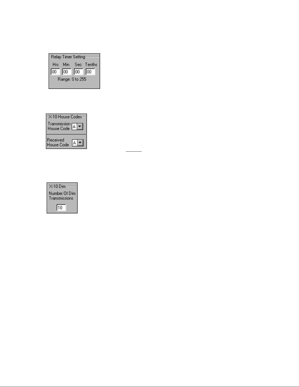
Settings / Build Tab
Application Template Program To Build From
The Application Writer uses a pre-built template program with a file type of .eap to reference as it builds the
program. The “CaddxHomeAutomation1.eap” program should be used as a template to build all programs. As more
template programs are developed, they will be available on our website at www.elkproducts.com
work properly if the .eap template program has been modified.
Note: Do Not Modify The “CaddxHomeAutomation1.eap”. Compilation of the .src program may not
.
Magic Module Program Name To Create
The Application Writer will create a new program with a file type of .src. This program may be named anything
that you would like to call it. The program may also be edited with the ELK Code Development Editor.
Code Editor custom features and operations that are not available through the Application Writer may be
added.
Through the
Magic Module Address
After the Application Writer finishes building the new program into an .src file, the file
will be automatically transmitted to the Magic Module that is addressed by the
Module Address
bus address set on the Magic Module.
If no Magic Module is connected to the computer or transmission to the Magic
Module is not desired, uncheck
If a ML8 – Magic Module to Caddx Data Bus Interface is not used, uncheck
– Caddx NX8 Connected To Bus
X-10 Timer Setting
If any X-10 Unit Code Settings Click Buttons display a “T” for Timer, the X-10 device
will be turned
the timer expires
button, the timer will be restarted for all devices that have been turned on with a “T” click
button.
The timer settings are in Hours (Hrs), Minutes (Min), and Seconds (Sec). The value
range of each time setting is 0 to 255 hours, minutes, and seconds.
NOTE: A time setting should not be less than two (2) seconds since a X-10 message
requires two seconds to transmit.
window. Make sure the address set into the window matches the data
the Transmit To Magic Module checkbox.
checkbox.
If a ML8 is used and this program is to initialize the ML8,
check the
Note: Only one Magic Module on the data bus should
initialize the ML8.
On for the timer setting that is in the X-10 Timer Setting and turn off when
. Should the timer be started by another X-10 device with a “T” on the click
“This module initializes ML8” checkbox.
Magic
the ML8
Elk Products, Inc 25 Magic Module Instructions, Rev. 5.3 L391
Page 26
Relay Timer Setting
X-10 House Codes
Module, the
Received House Code must be set to the same house code that is being transmitted from a X-10 device.
X-10 Dim
If a X-10 Unit Code Click Button is set to “D”, the X-10 module will be turned Off, then
the number of X-10 Dim Transmissions set in
Ten (10) transmissions are about ½ brightness, 20 transmissions will turn the lamp on most X-10
modules off.
If any Relay Click Buttons display a “T” for Timer, the relay will be turned On for
the timer setting that is in the
expires. Should the relay timer be started by another relay with a “T” on the click
button, the timer will be restarted for all devices that have been turned on with a “T”
click button.
The relay timer settings are in Hours (Hrs), Minutes (Min), Seconds (Sec), and
Tenths of Seconds (Tenths). The value range of each time setting is 0 to 255 hours,
minutes, seconds, and tenths of seconds.
Each X-10 device is associated with a
devices from talking to your neighbor’s X-10 devices.
There is a
devices in you house. The X-10 device such as a X-10 lamp module must have its House
Code set the same as the Transmission House Code. One X-10 House Code is available for
transmission using the Application Writer, however all 16 House Codes may be used with
modifications to the .src file using the ELK Development Software’s Code Editor.
If you are receiving
Transmission House Code with which you send commands to the X-10
Relay Timer Setting and turn off when the timer
House Code. This helps to keep your X-10
X-10 House Codes to trigger other functions in the Magic
X-10 Dim will be transmitted to the X-10 module.
Elk Products, Inc 26 Magic Module Instructions, Rev. 5.3 L391
Page 27
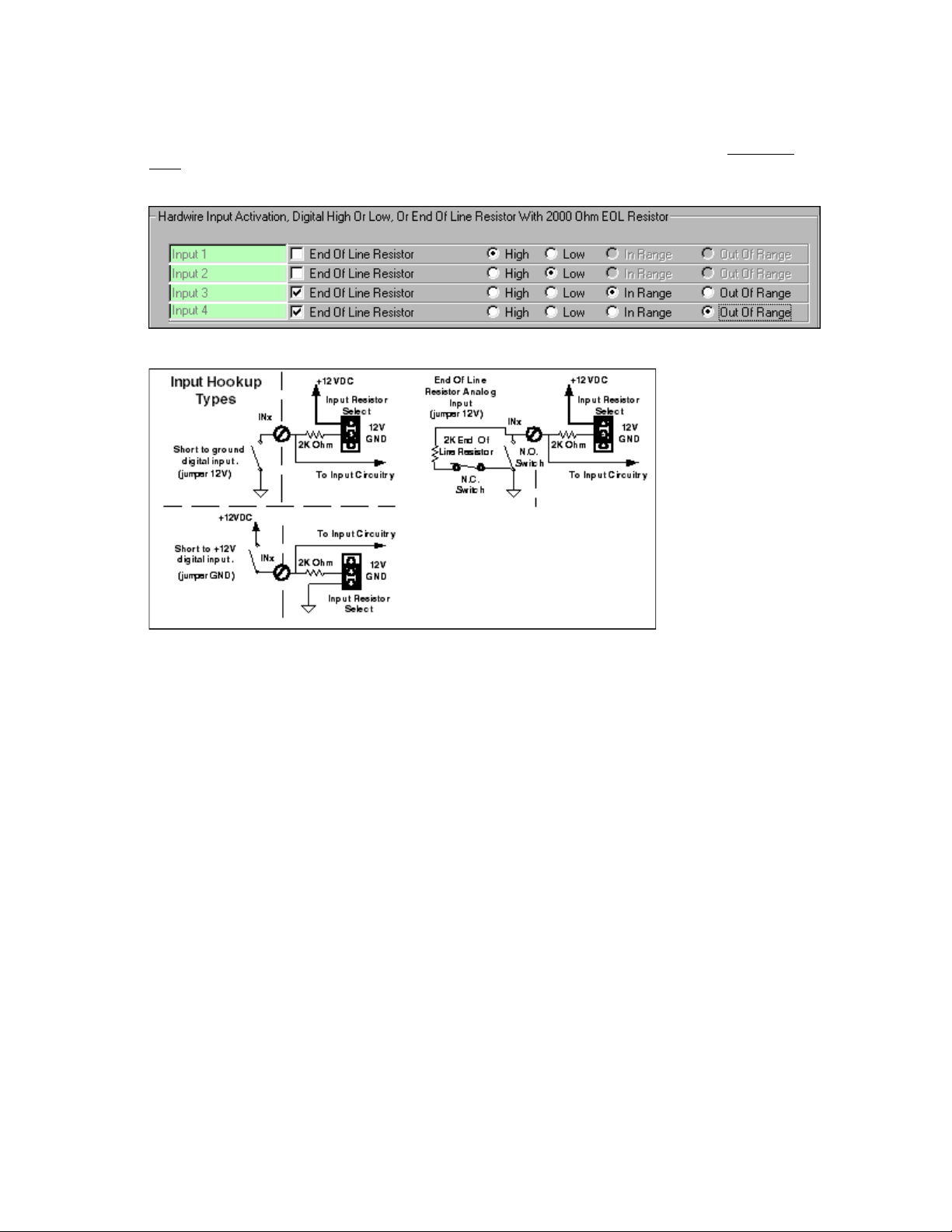
Hardwire Input Activation
Each of the four-hardwire inputs on the Magic Module may be configured as to how the input will be triggered
active. If the High or Low click boxes are selected the input will switch from a Hi to Lo state or Lo to Hi state at
approximately 6 volts.
Hardwire input switch hookups:
Normally Closed Switch: A normally closed security switch is closed when the magnet has closed
the switch or the door is closed. This is the most widely used type of security switch. This type of switch can be
supervised because all the switches are wired in series and if any switch opens, the entire loop opens. When this type
of switch is connected across the input terminal and negative, the hardwire input activation will be
voltage at the input terminal goes high to +12 VDC.
Normally Open Switch: A normally open security switch’s contacts are open when the magnet is
near the switch or the door is closed. This type of switch is wired in parallel and cannot be supervised from someone
cutting the wire. When this type of switch is connected across the input terminal and negative and the switch closes,
the hardwire input activation will be
If the
end of the switch loop between the input terminal and negative on the Magic Module, the four selections are:
End Of Line Resistor check box is selected and a 2000-ohm end of line resistor is connected at the
1.
2.
3.
4.
Make sure the input selection jumpers, JP1 to JP4, on the Magic Module are set to the “+12V”
setting.
Low. Therefore the voltage at the input terminal goes low to 0 volts.
High – The input will trigger active when the input voltage exceeds the high threshold
setting in the program which is set by the Application Writer at approximately 8 volts, or
when the input loop connected to the hardwire input terminal and negative opens.
Low – The input will trigger active when the input voltage drops below the low threshold
setting in the program, which is set by the Application Writer at approximately 4 volts, or
when the input loop connected to the hardwire input terminal and negative shorts.
In Range – The input will trigger active when the input voltage is between the low and
high threshold settings, 4 and 8 volts, or the end of line resistor is installed and the input
loop is not faulted.
Out Of Range – The input will trigger active when the input voltage is above the high
threshold setting, 8 volts, or below the low threshold setting, 4 volts. This is the option
that would normally be used for a burglar alarm input when the input loop faults open or
shorted.
High, where the
Elk Products, Inc 27 Magic Module Instructions, Rev. 5.3 L391
Page 28

Reset All Values
Build Application
Open/Save Settings
All buttons and settings are cleared to factory default.
Application Writer reads all click button settings and text fields and writes the Magic
Module .src program. The program may be changed and additional software features
added with the ELK Code Development Software Editor.
When exiting the Application Writer Program, all values will be saved in the
Windows registry and will be reloaded the next time the program is loaded.
The program settings may be saved to a disk file and reloaded later using the
“File” at the top of the Application Writer Screen.
Elk Products, Inc 28 Magic Module Instructions, Rev. 5.3 L391
Page 29

Code Editor
via the Code Transmitter Program.
The Code Editor edits and builds the intermediate code so that it can be transmitted to the Magic Modules
Program Listing Columns:
Add - Memory address of program line expressed in hexadecimal.
1.
C1 - Program code byte 1. The first byte of a code byte command. Expressed in hexadecimal.
2.
C2 - Program code byte 2. The second optional byte of a code byte command. Expressed in hexadecimal.
3.
C3 - Program code byte 3. The third optional byte of a code byte command. Expressed in hexadecimal.
4.
C4 – Program code byte 4. The fourth optional byte of a code byte command. Expressed in hexadecimal.
5.
Label - Designates an address position in the program for a goto, jmp, call, if, or event to redirect the program
6.
to.
Command - The 13 commands that direct the program to function:
7.
7.
8.
9.
10.
Directive - The directing part of the command that selects components such as inputs, outputs, counters, and
timers. Not all commands require the Directive part of the command.
Compare - The comparison part of the command that holds the comparison value. Not all commands require the
Compare part of the command.
Goto - The if command redirects the program to a new address identified by a Label and stored in the Goto
column.
Comment - The user may comment the program line to help explain what the program is doing. Up to 150
characters may be typed into the comment field. If the command is a
visible. If the Wizard button is pressed, the text “Wiz- What is “ is inserted into the comment line. The user may
add or modify the command line to explain the question that will be asked if the
Wizard program allows for quick editing of lines of code without knowing how the program works.
set command, the Wizard button will be
Wizard program is used. The
Elk Products, Inc 29 Magic Module Instructions, Rev. 5.3 L391
Page 30

Writing Code
Each line of code is written by filling in the appropriate blocks in the Code Edit Line. By clicking the down
arrow to the right of each block, a menu list of the available selections drops down. Click on the desired selection and
it will be placed into the Code Edit Line.
Insert
Program Line will then be placed into the Code Edit Line where changes may be made. After
changes are made, place the Code Edit Line back into the program by clicking on the Program Line
where the Code Edit Line should be
placed before the highlighted line.
Replace
Edit Line should be
highlighted line.
Compile
be sent to the Magic Module Controller. If any errors are found during the compilation, the red
ERROR flag will be displayed along with the address in hexadecimal where the error occurred.
Comments
A line of code may be commented by typing the comments into the comment line. If the command is a “set”
command the “Wizard” button will be displayed. If the Wizard button is clicked, the comment field will start with “Wiz-“.
This will allow the Wizard Program to make changes to that line of code.
Any line in the program may be edited by “Double Clicking” the Program Line. The
Inserted. Click on the Insert button. The edited code will be
After changes are made to the Code Edit Line, click on the Program Line where the Code
Replaced. Click on the Replace button. The edited code will replace the
After editing the program, press the Compile button to regenerate the code bytes that will
Code Space
memory. This memory is stored in a non-volatile EEProm memory.
Elk Products, Inc 30 Magic Module Instructions, Rev. 5.3 L391
The amount of memory space available to store program instructions. There are 16384 bytes of program
Page 31

Save Label
A label may be added to the label list to be used later without having to type the label
name again.
Right Mouse Click (in Code Editor program area)
Copy - Highlighted Program Lines are copied to a clipboard for storage.
Cut - Highlighted Program Lines are cut from the program and copied to a clipboard for storage.
Delete - Highlighted Program Lines are deleted from the program.
Insert - Insert the Code Edit Line before the highlighted Program Line.
Paste - Insert the program lines stored from a copy or cut into the program before the highlighted Program Line.
Replace - Replace the highlighted program line with the Code Edit Line.
Code Writer - Provides several programs for automatically writing application program subroutines and initialization
setup. See
Comment/Uncomment - The program lines that are highlighted will be commented out of the program with a single
quote as the first character of the Command instruction. A null will be placed into the program code at that location. If
the code is already commented out, it will be
program. The single quote comment should not be confused with the semicolon “;” comment that is used to add
comments to the line for documentation or line spacing.
Insert; Comment - Inserts a comment line at the highlighted Program Line. The single “;” must be the only character
in the Command field. The comment field may be edited to add text for explanation. No other commands may be
present in any other fields. Use the
New / Build Structure - Starts a new program and gives the option to automatically build the program structure with a
title, description area, initialization area, program area, subroutine area, and data area. This provides a starting
template to make programming easier.
Code Writer section.
Uncommented and the normal program code will be compiled into the
Comment/Uncomment to temporarily remove a line of program code.
Open - Opens an existing file to be edited.
Save - Saves a file that has been edited and previously saved with the Save As button.
Save As - Initially saves an edited file and allows for renaming the file to a new name. This should always be
used before the
Transmit -
Magic Module that is set in the address field on the Transmit Screen.
Save button is used to initialize the file name.
Provides a shortcut to get to the Transmit Screen to send the file that is being edited out to the
Elk Products, Inc 31 Magic Module Instructions, Rev. 5.3 L391
Page 32

Event Programming Description
Events are occurrences that trigger the program to call a subroutine. When the subroutine is finished,
denoted by the
The following occurrences can generate an Event:
At the beginning of a program the event must be declared with a “set” command. The “set” command will include the
event name such as “EvtTMR1” for timer 1 event and the label where the event subroutine is located. At the end of
the subroutine a “return” command must be inserted.
Example: Toggle relay 1 on or off every 5 seconds:
begin set EvtTMR1 TimEvt ;setup timer 1 Event at label “TimEvt”
loop jmp loop ;loop forever waiting on an event to occur
; ;when Timer 1 counts down to 0 the event is triggered
;
TimEvt set OUT1 toggle ;alternate relay 1 on or off
set T1SEC 5 ;WIZ- set delay time in seconds.
return ;return from the Event
Note: if “WIZ-“ is entered as the first characters in the comment field of a “set” command, the Wizard Program will
allow the value to be changed easily. Try running the Wizard Program with the example above.
return statement, program execution continues at the next program location before the event occurred.
1. Timer 1 reaches 0. (
2. Timer 2 reaches 0. (
3. Timer 3 reaches 0. (
4. Timer 4 reaches 0. (
5. Input 1’s analog value has moved past the high or low threshold settings. (
6. Input 2’s analog value has moved past the high or low threshold settings. (
7. Input 3’s analog value has moved past the high or low threshold settings. (
8. Input 4’s analog value has moved past the high or low threshold settings. (
9. X-10 message is received.
FVAL will hold the Function value upon entering the subroutine. (EvtRX-10
10. Real Time Clock (RTC) minute has passed. Once a minute a RTC Event will occur. (
11. RS-485 data bus message has been received. This occurs when a message with the proper type and
address has been received on the data bus. (
12. RS-485 data bus has been lost. (
13. Local Temperature has changed by at least one-degree celcius. (
Dallas iButton read enabled. (EvtTKey) A Dallas iButton or 26-bit Wiegand reader can be read
14.
through the optional MA100 or the MA290 access reader interface, which plugs into connector J5. Use
Code Writer to automatically write the program code. UVAL = ID number, FVAL = reader number:
the
0 = reader 1, 1 = reader 2
EvtTMR1)
EvtTMR2)
EvtTMR3)
EvtTMR4)
EvtIN1)
EvtIN2)
EvtIN3)
EvtIN4)
RHOUSE must be set with the house code. UVAL will hold the Unit value;
EvtRTC)
EvtRXBus)
EvtNoBus)
EvtTEMP)
call TimEvt ;initialize Timer1 to 5 seconds
Elk Products, Inc 32 Magic Module Instructions, Rev. 5.3 L391
Page 33

Code Writer
The Code Writer uses a graphical user interface to answer questions and then generates
the program according to the questions answered. Note: Additional tabs may show up on your software and will be
fully supported in the future.
There are eight (8) categories for the Code Writer to use for automatically writing Magic Module Program
Code:
1. Input Event
2. Timer Event
3. Receive X-10 Event
4. Data Bus Receive Event
5. Dallas iButton Reader or 26 bit Wiegand ( Prox Card)
6. X-10 Transmit
7. Data Bus Transmit Event
8. Real Time Clock Event
SIMPLE code into
Elk Products, Inc 33 Magic Module Instructions, Rev. 5.3 L391
Page 34

Input Event
Each of the four (4) analog inputs can generate an event (or sometimes called an interrupt) when the input
level crosses either the high or low threshold level. From the factory these levels are set at 126 for the high level and
125 for the low level and the input acts as a digital input with the input either being high or low with no InRange
(between high and low thresholds) area. To generate the code follow the three-step setup:
Step 1 -
• Input Select - Selects input ( IN1 to IN4). If the input has already been used the selection will be grayed out and
cannot be selected.
• Input Description - Describes what the input will be used for. Example: Front Door, Kitchen Door, and Tank
Level. This code will be added to the comment field. A description longer that 20 characters will be truncated.
• Filter Time - The input filter time is in 1/10-second increments with a range from 1 to 255 (1/10 second to 25.5
seconds). The input filter time is sometimes call loop response time. It is the amount of time the input must
remain in the High, Inrange, or Low state before it is recognized as being in that state before generating an event.
Because the processor only increments the timer every 1/10 of a second, the filter time will have a +/- 100
milliseconds resolution, a value less than 2 or 2/10 of a second should not be used to insure a minimum of 100
milliseconds filter time. A value of 0 will disable the filter time.
Step 2 -
• Set Thresholds In Code - When checked the Code Writer will place the custom high and low input thresholds
into the code. Move the high and low slider bar to the desired voltage setting. An input level above the High
Threshold setting is interpreted as a high state. An input level between the High Threshold and the Low
Threshold is interpreted as an InRange state. An input level below the Low Threshold level is interpreted as a
Low state.
Step 3 -
• Skip If - Checks for the inputs to be in the High state, InRange state, not InRange state, and Low state. If true
the subroutine will be skipped.
Input Event Label - Code Writer automatically selects labels to be inserted into the program code. Normally this field
should not be changed.
Elk Products, Inc 34 Magic Module Instructions, Rev. 5.3 L391
Page 35

Timer Event
Each of the four (4) timers on the MM443 can generate an event when the timer counts down to zero. Follow
the three steps for programming the event:
Step 1 -
• Timer Select - Selects timer (Timer1 to Timer4). If the timer has already been used, the selection will be grayed
out and cannot be selected.
• Timer Description - Describes what the timer will be used for. Example: Exit Delay, Alarm Timer, And Relay On
Timer. This code will be added to the comment field. A description longer that 20 characters will be truncated.
Step 2 - Optional
• Tenths Second Set - Set the tenths of a second value. Range 0 to 255 (0 to 25.5 seconds).
• Seconds Set - Set the seconds value. Range 0 to 255 (0 to 255 seconds).
• Minutes Set - Set the minutes value. Range 0 to 255 (0 to 255 minutes).
• Hours Set - Set the hours value. Range 0 to 255 (0 to 255 hours).
Any combination of tenths, seconds, minutes, and hours may be entered. When all the timer settings count
down to zero, the event will be triggered.
Step 3 - Optional
• Preload Time In Setup Area - When the program starts, the timers will be initialized as set if the checkbox has
been checked.
• Reload Time In Event Subroutine - When the timer event is activated, the timers will be reloaded in the timer
event subroutine if the checkbox has been checked.
Timer Event Label - Code Writer automatically selects labels to be inserted into the program code. Normally this field
should not be changed.
Elk Products, Inc 35 Magic Module Instructions, Rev. 5.3 L391
Page 36

X-10 Receive Event
This program sets up MM443 to receive X-10 power line transmissions using a TW-523, PSC05 two-way X-10
module plugged into J5 X-10 port.
Follow the two steps to setup to receive X-10:
Step 1 -
• X-10 Description - Describes what the received X-10 signal will be used for. Example: Outside Flood, Light
Switch, Hall Light. This code will be added to the comment field. A description longer that 20 characters will be
truncated.
Step 2 -
•
House Code - The X-10 House Code that the TW-523, PSC05 will receive and generate a X-10 Receive Event.
All other house codes will be ignored.
•
Broadcast X-10 Data to other Magic Modules on Data Bus - When checked, any X-10 message will be re-
broadcast on the RS-485 Data Bus so that other Magic Modules can receive the X-10 transmission without
having a X-10 power line interface connected to them.
Label
field should not be changed.
When the proper house code has been received, the X-10 unit value will be placed in
tested with an
be tested with an
X-10 Receive - Code Writer automatically selects labels to be inserted into the program code. Normally this
UVAL so that it can be
if statement. The X-10 function value (“On, Off, Lights On, Dim”) will be placed in FVAL so that it can
if statement.
Elk Products, Inc 36 Magic Module Instructions, Rev. 5.3 L391
Page 37

Data Bus Receive Event
This event is generated when a received data packet on the RS-485 data bus matches the Magic Module
Type of 3 and the Address that is set on the address jumpers. The received command is placed into
data byte is placed in
so that they may be tested with an
Step 1 -
•
Data Bus Description - Describes what the received Data Bus Data will be used for. Example: Module 1
Relay, Module 2 Input 1, And Remote Tank Level. This code will be added to the comment field. A description
longer that 20 characters will be truncated.
Label
Data Bus Receive - Code Writer automatically selects labels to be inserted into the program code. Normally this
field should not be changed.
RDAT1, and the second data byte is placed in RDAT2, the received Type is placed into the Type
if statement.
RCMD, the first
Elk Products, Inc 37 Magic Module Instructions, Rev. 5.3 L391
Page 38

Dallas iButton Reader or 26 Bit Wiegand Reader (Prox Card)
The MM443 can read and store Dallas iButton ID modules or 26 bit Wiegand format Prox or Swipe Cards.
This can be used for access control or product identification. Each Magic Module can hold over 1000 key codes in the
program memory. This will vary with the length of the program code that is also included into the program space.
Additional Magic Modules connected to the data bus can also hold more key codes. The key codes will be shared on
the data bus.
This program will initialize the
interfaced to an optional
conductor telephone style cable plugged into J5 or make your own cable as follows:
MA100 Access Key reader interface that is plugged into port J-5. Use the provided 8
access reader on the MM443 that is addressed. The Magic Module must be
Reversed
8 Pin, 8 Conductor
Pin 1 to Pin 1
After initialization, touch the
code. Click on “OK” to write the event code into the program.
Note: X-10 cannot be used at the same time as the reader interface on the same MM443.
.
When a valid key is read,
reader and the code does not match any codes stored in the local Magic Module or any codes stored in remote Magic
Modules on the RS-485 Data Bus, the
for the proper button ID to allow selected button ID’s to access certain doors. Note: UVAL should be preset with a “set
UVAL 255” command if checks are being made for invalid keys.
Dallas iButton or present the prox card to the reader. Click on “Apply” to store the button
UVAL will return the button ID of the user. When a key is touched to the MA100(W)
UVAL will be set to a 0 two seconds later. An if statement can check the UVAL
Follow the three (3) steps:
Step 1 -
• Address/Type 3 - Set the address of the MM443. The address must match the Data Bus Address Jumpers that
are set on the MM443 board. Range 1 to 31.
• Save as Remote Storage - Save the key data as storage only, to be accessed by other MM443’s on the RS-485
data bus.
Step 2 -
• Get Key Data - Press “Enable Touch Key Read” button. The Magic Module will be initialized to read an access
key and send the ID Code back to this program. The Status Window will indicate the status of the remote
MM443. Press “Enable Touch Key Read” button each time a new access key is to be read.
Elk Products, Inc 38 Magic Module Instructions, Rev. 5.3 L391
Page 39

• Auto Store - Enables the automatic storage and re-enabling of the access key reader in the Magic Module.
Step 3 -
•
Button ID - The Button ID identifies the access key user or security level of the user. It should be in the range of
1 to 255. An access key ID value of
for a convenient way to take a user out of the system, but not erase his code. The access key ID will be placed in
UVAL in the MM443 when it reads an access key, so that it can be tested with an if statement for the proper ID or
security level check. An ID of
• Comments - This field can be used to identify the access key user. Example: Kirk, Don, Joe, etc. This field will
be added to the comments in the program code.
• Dallas iButton Code Read - This field will display the code of the access key. This can be used to verify the
access key
• Dallas iButton Label - Code Writer automatically selects labels to be inserted into the program code. Do not
change the label names
is working correctly.
0 is returned in the UVAL when no code match is found. This feature allows
0 in UVAL should be considered no code match.
X-10 Transmit
X-10 Transmit builds a data structure in the MM443 for the transmission of X-10 Power Line data packets.
The MM443 is interfaced to a PL-513, PSC04 (X-10 one way transmit only) or a TW523, PSC05 (X-10 two way
transmit and receive) power line interface available from your distributor. Jack J5 on the MM443 plugs into the X-10
interface with a 4 pin telephone style connector cable wired pin 1 on one connector end to pin 4 on the other telephone
connector end (standard telephone cord, 4 conductor). Jumper JP-10 should be set for the proper one way or two way
X-10 interface.
Code Writer will automatically place the
code line. Follow the three steps:
Step 1 -
•
X-10 House Code - Sets the X-10 House Code to be transmitted. Range: A to P.
Step 2 -
•
X-10 Unit Code - Sets the X-10 Unit Code to be transmitted. Range: 1 to 16. To identify an X-10 Unit Code, the
unit code is preceded with a “_”.
“csub TX-10 label” into the program code before the highlighted program
Elk Products, Inc 39 Magic Module Instructions, Rev. 5.3 L391
Page 40

Step 3 -
•
X-10 Function Code - Sets the X-10 Function Code to be transmitted. Predefined codes are:
• All Off = 85
•
All On = 86
•
On = 89
•
Off = 90
•
Dim = 101
•
Bright = 102
•
Preset DimA = 153
•
Preset DimB = 154
•
Lights Off = 105
•
StatusReq = 170
•
StatusOn = 166
•
StatusOff = 169
•
Analog Input 1 = 1
•
Analog Input 2 = 2
•
Analog Input 3 = 3
•
Analog Input 4 = 4
•
Temp = 5 (Local Temperature)
•
Rtemp = 6 (Remote Temperature)
Note: The X-10 transmission of the analog voltage level from Input 1 to 4, Temp, and Rtemp can only be used
between Magic Modules. A special extended protocol is used that is decoded by another Magic Module. The
analog value is placed in FVAL in the receiving Magic Module which can be used by an “if” statement for
program control. The special protocol is: extended function, high nibble of analog data, and low nibble of
analog data. This command uses: “csub TX10INP label”.
Broadcast X-10 Data to other Magic Modules on the Data Bus - When checked, any X-10 transmission on the
•
power line will also be broadcast on the RS-485 Data Bus so that other Magic Modules can receive the signal.
The House Code (Rhouse) may be different for each Magic Module on the data bus.
•
If the Dim command is selected, the Number Of Dims window will be visible. Enter the number of dims to be
transmitted. Normally 20 dims will go from bright to off.
• If Preset DimA or B is selected, the “Preset Dim Level” window will open. Magic Module uses the X-10 standard
extended Preset Dim Values with the low level settings 1 to 16 set with function command “
Preset Dim high-level settings 17 to 32 are set with function command
“Preset DimB” using values 1 to 16.
Preset DimA”. X-10
Preset Dim commands must be issued from the Magic Module that is connected to the X-10 power line interface.
A custom data bus command from another Magic Module on the data bus may be sent to the Magic Module
connected to the X-10 power line interface to trigger a Preset Dim transmission.
• Comments - This field can be used to identify the X-10 transmission. This field will be added to the comments in
the program code.
*
Select OK and the “csub TX-10 label” command line will be added to the program code before the highlighted
program line.
Note: X-10 cannot be used at the same time as the Dallas iButton or 26 bit Wiegand reader on the same
.
.
MM443
X-10 Anti-Collision – An anti-collision algorithm is implemented into the MM443 Magic Module when using a two-way
X-10 power line interface module such as the PSC05 or the TW523. The Magic Module will listen for X-10 power line
traffic and when the line is clear, transmit its data. While transmitting, the Magic Module will listen for other X-10
transmissions that could be interfering with the signal. If any collisions are detected, the Magic Module will back off the
power line and wait for no other interfering X-10 transmissions before re-transmitting its X-10 data.
Elk Products, Inc 40 Magic Module Instructions, Rev. 5.3 L391
Page 41

Data Bus Transmit
Magic Module to Magic Module transmission:
Magic Module to MV120 (MV480) Voice Module transmission select Type 4 in Step 2 first:
program line. Follow the two steps to build the structure:
Step 1 –
Select the “Type To” – Type 3 = Magic Module MM443, Type 4 = Voice Module MV120
Elk Products, Inc 41 Magic Module Instructions, Rev. 5.3 L391
Data Bus Transmit builds the data structure and places the “csub TXBus label” before the highlighted
•
Command selection for Type = 3, Magic Module - Double click the command to transmit:
• 33 - Request EEprom Data - Enter the address of the EEprom memory location to get data
from.
• 34 - Request Analog Input Data - Get the input port analog level of the selected port.
• 35 - Write Output data - Turn on, off, toggle the selected output relay port.
• 36 - Request Output Data - Get the state of the selected output relay port, i.e. “On”, “Off”.
Page 42

• 37 - Write X-10 Command - Instruct another Magic Module to transmit an X-10 command.
Note: Will not transmit extended Preset Dim commands to another Magic Module.
• 38 - Request to Run - Instruct another Magic Module to start running its program code.
Normally done after a Request to Stop command has been issued.
• 39 - Request to STOP - Instruct another Magic Module to stop running its program code.
• 41 - Read Temperature - Get the remote temperature from an optional temperature sensor
connected to a remote MM443.
• 99 - Custom Transmission - The user can transmit any code to another Magic Module to
activate custom devices. The custom command code should start above 50. RDAT1and
RDAT2 may be any value from 0 to 255.
•
Command selection for Type = 4, Voice Module - Double click the command to transmit:
• 32 – Say Voice Message – Say the voice message selected from 1 to 32.
• 33 – Stop Voice Message – Stop saying the current message that is playing.
• 34 – Record Voice Message – Place the next message that is recorded in to the message
address selected. This command only enables the recorder to start when the record button is
pressed on the Voice Module.
• 35 – Request Voice Status – Requests the “Busy” = 1 or “Not Busy” = 0 status of the Voice
Module, which is returned in RDAT1. This may be used with an
control.
On the response from a Magic Module, the remote module will place the command in RCMD, the first data
byte in RDAT1, and the second data byte in RDAT2 to be used with an
Step 2 -
•
After double clicking the command, data will be entered into the appropriate fields according to the data
required by the command.
• Enter the Type to transmit to.
• Enter the Address to transmit to.
• According to the command, other data may be required to be changed in the 1
comments in the program code.
Comments - This field can be used to identify the Data Bus transmission. This field will be added to the
if statement to direct the program.
if statement for program
st
, 2nd, or 3rd data fields.
Note: Do Not “HOG” the data bus. A constantly transmitting Magic Module will lock
the data bus and the computer will not be able to control or re-program the module. If this condition should
exist, the program will have to be erased by holding shorted “TP1” on the PC board, and powering up the
module. Then release the short on “TP1”. The computer can now gain access to the module for reprogramming.
Elk Products, Inc 42 Magic Module Instructions, Rev. 5.3 L391
Page 43

Real Time Clock (RTC) Event
if a MC100 Real Time Clock Module is installed onto the MM443 at J1, a Real Time Clock Event (RTC
Event) will be generated each minute. This program automatically writes program code to check if a RTC time has
occurred. Follow the three steps to build the program code:
Step 1 -
RTC Description -
comments in the program code. This field should be limited to 20 characters.
Step 2 - Set any of the Real Time Clock Time Functions:
• Minute - Range 0 to 59 minutes.
• Hour - Range 0 to 23 hours set in military time.
• Day - Range 1 to 31 days of the month. Make sure the number of days does not exceed the number of
days in a selected month.
• Weekday - Range Sunday to Saturday. Make sure the Weekday is a legal day of the week.
• Month - Range January to December. Make sure the Month is a legal month of the year.
Step 3 -
•
Skip if = RTC - The Code Writer will automatically write code that will exit the event if the RTC time
function matches the RTC.
•
Skip if not = RTC - The Code Writer will automatically write code that will exit the event if the RTC time
function does not match the RTC. This is the normal setting to check if a RTC event has happened.
Note: If the Real Time Clock Module is mounted on Magic Module Address 1, the time will be broadcast each
minute to all other Magic Modules connected to the Magic Bus Network.
This field can be used to identify the RTC Time Event. This field will be added to the
Elk Products, Inc 43 Magic Module Instructions, Rev. 5.3 L391
Page 44

ASCII Text String Transmission
The Magic Module may transmit ASCII text strings. These ASCII text strings are primarily used for RCS Thermostats,
but may be configured for other devices. The string will be transmitted on the data bus at 19,200 baud, no parity, 1
stop bit. Special characters may be embedded into the string:
\r = carriage return = 13
\L = line feed = 10
Any other “\” + ASCII character will mask the ASCII character value with 1F hex.
Example:
\A = 0, \B = 1, \C = 2 …
When using the RCS Thermostat on the return string which is requested with R=1, the temperature (T=) value will be
placed in the RTEMP variable, the set point (SP=) value will be placed in RDAT1 variable, and the mode (M=) value
will be placed in RDAT2 variable. Upon reception of the data string from the RCS Thermostat, a data bus receive
event will be triggered if enabled by the “set EvtRXBus label” program instruction.
For best results when using the RCS Thermostat, precede the ASCII string with a carriage return (\r).
Thermostat must be a 19,200-baud, RS-485 data bus version.
RCS Data Bus to Magic Module RS-485 Data Bus Hookup:
RCS Magic Module
G NEG
T+ Data A
R- Data B
The standard RCS command string is to RCS address 1, requesting basic temperature status feedback.
Note: The RCS
\rA=1,R=1\r
Elk Products, Inc 44 Magic Module Instructions, Rev. 5.3 L391
Page 45

File - Drop Down Menu in Code Editor
• File Insert - Inserts a Magic Module .src file
before the highlighted program code line.
• Print - Prints the Code Editor edited file to a
printer or file.
Edit - Drop Down Menu in Code Editor
• Compile - Re-Generates the code bytes that are sent to
the Magic Module. The program will automatically be
compiled before a
• Delete - Removes the highlighted code from the program.
• Insert Title - A program title can be inserted into the
program by entering the program title name and clicking “Insert Title”. The title will be placed at the top of the
program.
automatically call this program.
•
Code Writer - Executes the Code Writer program, which simplifies the writing of event driven programs.
•
Comment/Uncomment - Replaces program lines that are highlighted with null code by adding a single quote in
front of the command instruction. Highlighting the lines again and executing Comment/Uncomment will place the
normal code back into the program.
•
Documentation - Opens the Notepad text editor and assigns an associated program name to the file being
edited for user documentation of the program being written. The program .src file must be saved before the
“Program Documentation” button will appear.
No other program code should be placed before the title data. The New command will
Save or Save As
Window - Drop Down Menu in Code Editor
• Display Hex Address and Data - The Address and three data columns can be made to disappear by clicking this
menu option. For some programmers that are not concerned with the address and data, the display will be less
confusing. The address and data columns are displayed in hexadecimal as two characters.
• Edit Line Drop Down Length - The number of selections that are displayed when an edit box is clicked on the
edit line may be changed with this option. The normal setting is 20 options. With larger display screens 40 or
more options may be selected.
• Display Opening Screen - The first time the Code Editor is started a screen will appear that asks to start a new
program or open an existing program. The screen will not be shown again. Click this menu option to make that
screen re-appear.
Elk Products, Inc 45 Magic Module Instructions, Rev. 5.3 L391
Page 46

To change the title after it has been entered into the program:
1. Delete the existing Title Program Lines by highlighting them and pressing Delete, then
2. Execute “Insert Title” program again, located in the Edit drop down menu.
Elk Products, Inc 46 Magic Module Instructions, Rev. 5.3 L391
Page 47

Simulator - Debugger
The Simulator allows code written on the Code Editor to be executed and debugged under software control. Display
windows are available to view timers, counters, registers, and stop the program at specific addresses. X-10 and Data
Bus transmission and reception can be simulated to test the program function.
Simulation Screen
The Simulation Screen is the main simulator display screen, with the most used inputs and outputs displayed.
Always
Note: Some commands cannot be simulated using the Simulator-Debugger and will be
skipped when the program executes, like the Dallas iButton, and multiple Magic Module
communication on the data bus. Simulation should be limited to small routines.
Save the file when in the Code Editor, and then Open the file when starting the Simulator.
Receive X-10 Simulation:
“HOUSE” is set by the set RHOUSE value in the program and displayed in the HOUSE window.
1.
2.
Set the UNIT code to be received with the drop down window at “Set Unit”.
3.
Set the FUNCTION code to be received with the drop down window at “Set Function”.
The decimal Function Value will be calculated and displayed in the “Function Value” window.
4.
5.
Click on the Receive X-10 button to simulate the reception of an X-10 signal.
UVAL will hold the Unit Value, and FVAL will hold the Function Value to be used with an if statement for
6.
further program control.
Input Level Simulation
Adjust the sliding input bar on each input to simulate an input change. The High and Low Threshold levels will
be displayed as well as the corresponding simulated input voltage levels.
Elk Products, Inc 47 Magic Module Instructions, Rev. 5.3 L391
Page 48

Simulate Registers
Displays timers, counters, and X-10 receive values.
any timers that have been programmed with a time value are
decremented. Normally the timers will continue to decrement when
the program has been stopped by the simulator when an address
that is set in the
Screen is executed. By clicking the checkbox, the timers will stop
decrementing.
faster by not updating the timers every 100 ms. Uncheck this box to
not update the timer display every 100 ms.
seconds, minutes, and hours are displayed in the timer display area.
Every 100 ms the display will be updated.
displayed in the Counter Data area. The count value will be
between 0 to 255. The count value may be initialized with the “set”
command and compared with the “if” command. When the count
increments past 255, it will roll over to 0. When the count
decrements below 0, it will underflow to 255.
receive X-10 is not being used, UVAL may be used as a temporary
storage location. The value may be initialized with the “set”
command and compared with the “if” command. UVAL may also be
used by the
user.
function value is the “On”, “Off”, “Dim”, etc. X-10 functions are expressed as a decimal value. When receive X-10 is
not being used, FVAL may be used as a temporary storage location. The value may be initialized with the “set”
command and compared with the “if” command.
Stop 100ms Timer at a break - Every 100 milliseconds
“Break At Address” in the Program Control
Update Data - A simulation program can be made to run
Timers - Timer 1 through Timer 4 with tenths of a second,
Counters - Counter 1 through Counter 4 count value are
UVAL - UVAL is the received X-10 Unit Value. When
Dallas iButton or 26 bit Wiegand reader to identify the
FVAL - FVAL is the received X-10 Function Value. The
Elk Products, Inc 48 Magic Module Instructions, Rev. 5.3 L391
Page 49

Program Control
set in “Break Address”. Reference the hexadecimal address of the program code line in the Code Editor to set the
hexadecimal address.
in the Code Editor is set in the “Break Address” to stop execution when the
program has reached that address. The “Break Enabled” must be checked for
the “Break Address” to stop the program.
or is single stepped, the current hexadecimal address will be displayed here.
occurs, the return address in the program is placed in a storage area called
the “stack”. The program will jump to the subroutine and execute the program
code located in the subroutine. At the end of the subroutine is a “return”
command. The “return” command directs the program to pull the last address
that was placed on the “stack” and resume the program at that location.
MM220 and MM443 can have four (4) levels of stack. In other words the
program can “call” a subroutine, which can “call” a subroutine, which can “call”
a subroutine, which can “call” a subroutine and they may all “return” back to
the original program line to continue executing the program.
“call” to a subroutine is executed, the program will not “return” to the
original program line and fail to execute properly. An error will be
indicated in the Debugger indicating a stack overflow error.
Single Step Enabled -
the next command line, click the red “Continue” button. Each click of the “Continue” button will display the results of
that command line instruction. This can be very useful in debugging programs that do not work properly.
Local Temperature -
(TEMP) can be compared with an “if TEMP” command. Temperature is always expressed in degrees Celsius.
Example:
if TEMP >= 22 TooHot ;Temperature is too hot, skip
set OUT1 On ;When Cold Turn On Heater
TooHot
If another MM443 with a Real Time Clock Module has broadcast its temperature (RTEMP), it can be compared with an
“if RTEMP” command. Temperature is always expressed in degrees Celsius.
Example:
if RTEMP < 15 TooCold ;Remote Temperature is too cold
set OUT1 On ;When Hot, Air conditioner On
TooCold
Save Window Position -
desired. When the screens are in the desired position click “Window/Save Window Position”. The next time the
Simulation windows are displayed, they will be in the saved position.
Break Enabled - The “Break Enabled” click box enables the program to stop executing code at the address
Break Address - The hexadecimal address of the program code line
Stopped At Address - When the program stops at the break address
Stack Level - When a “call” command is executed or an event
If a fifth (5)
When checked, the program will execute one (1) command line at a time. To execute
If a Real Time Clock Module is installed in the MM443, a local temperature value
continue program
Remote Temperature -
continue program
The Debugger Windows may be moved and resized to display the screens as
Elk Products, Inc 49 Magic Module Instructions, Rev. 5.3 L391
Page 50

Save Window Position -
and resized to display the screens as desired. When the screens are in the
desired position click “Window/Save Window Position”. The next time the
Simulation windows are displayed, they will be in the saved position.
The Debugger Windows may be moved
Transmit/Remote Control
(Send data to and remote control Magic Modules on the data bus)
Setup
Software- The Transmit Program communicates with MM443 by way of the RS-232 serial port. The Serial
Communications port is defaulted for CommPort 1. Use the CommPort/Settings to select a different serial
communications port. The
serial communications line and the MM443 RS-485 data bus.
Hardware - The MB485, RS-232 to RS-485 converter box, has four terminals:
1.
+12V - +12 volts DC. This should connect to +12V on MM443.
A - The “A” RS-485 Data Line. This should connect to “A” on MM443.
2.
B - The “B” RS-485 Data Line. This should connect to “B” on MM443.
3.
NEG - The negative, common terminal of the power supply. This should connect to “NEG” on MM443.
4.
Note: Data Bus Lines “A” and “B” must connect to “A” and “B” respectfully. The data bus will not work if the
data bus lines are cross connected.
MM443. The Data Bus Address Jumpers are either in position “0” or position “1”. The values of the jumpers are 1, 2,
4, 8, and 16. Jumpers should be placed in the “1” position that add up to the desired address.
Example address 5:
Set jumper 1 to the “1” position
Set jumper 4 to the “1” position
All other jumpers should be in the “0” position
Jumper 1 + Jumper 4 = 5 as the address for the MM443.
Example address 25:
Set jumper 1 to the “1” position
Set jumper 8 to the “1” position
Set jumper 16 to the “1” position
All other jumpers should be in the “0” position
Jumper 1 + Jumper 8 + Jumper 16 = 25 as the address for the MM443.
center of the power plug is “+” positive.
Note: The power supply must be regulated when reading analog voltage levels. If the power supply is not
regulated, the voltage level will shift as relays and loads are turned on and off.
the ELK-624, with 12VDC output and rated at least ½ amp current. The current ratings of the power supply may need
to change according to the load drawn by the modules powered by the power supply.
that the module is in the “RUN” mode.
Magic Module Address - The MM443’s Address must be set to an address that is not used by any other
Power Supply - Plug a 12VDC, ½ amp or greater plug-in power supply into “Power Conn. J3” on MM443. The
Alternative Power Supply - Connect “+12” and “NEG” on the MM443 to a regulated power supply such as
Status LED - When power us first applied to the Magic Module, the Status LED should start to flash indicating
MB485, RS-232 to RS-485 converter box, must be installed between the RS-232 computer
Elk Products, Inc 50 Magic Module Instructions, Rev. 5.3 L391
Page 51

Transmit Screen
RS-485 Data Bus Display -
String Send (RCS Thermostat)
In the Magic Module 16384 byte memory version, an ASCII string command may be transmitted. See RCS
Thermostat documentation for building the string. The string included in the window (\rA=1,R=1\r) will request the
basic temperature status from address 1. The string \rA=1,SP=70\r will set the thermostat set point to 70 degrees F.
Note: Always precede the ASCII string with a carriage return (\r). The returned data string from the RCS Thermostat
will be visible in the
Data Bus Transmit & Receive Data Display if enabled.
Elk Products, Inc 51 Magic Module Instructions, Rev. 5.3 L391
Page 52

Window Drop Down Menu (Transmit Program)
Save Window Position - Adjust window size and
position and click “Save Window Position” so that
each time the program is reopened, all windows will
be in the same position.
Transmission Window -Hide/Unhide - The data bus
data transmission window may be shown or hidden by
clicking this option.
X-10 Monitor Window - X-10 signals received and
transmitted may be displayed on the X-10 Received
Display Screen. Note: “
EvtRX-10 (label)”
executed in the MM443 program that has the X-10
power line interface connected to it. This command
instructs the MM443 to broadcast all X-10 signals on
the data bus. These commands may be entered into
the program with the CodeWriter X-10 Receive Event.
The X-10 data received may be saved to a text file
File/Save screen.
with the
Hide/Unhide Display Windows – Additional windows
may be hidden or displayed by clicking the
appropriate window title name. Each window may be
moved by clicking and dragging the window.
set X10Bcast” and “set
commands must have been
Elk Products, Inc 52 Magic Module Instructions, Rev. 5.3 L391
Page 53

X-10 Received Data
will be displayed according to the transmission received, XMIT#, the House Code, the Unit Code,
the Function Code, and the Date/Time Stamp.
X-10 Transmitted Data is selected by clicking on the “X-10 Transmit Function” and selecting the function to transmit,
then clicking on the appropriate House/Unit Button. The transmitted data will be displayed with a “TX” in the XMIT#
column. The color of the button will change according to the state of the X-10 device: yellow = On, green = Off.
Elk Products, Inc 53 Magic Module Instructions, Rev. 5.3 L391
Page 54

Data Bus Transmit & Receive Data Display
Type - The module type that is
communicated to.
Address – The address from 0 to
31 of the module that is being
communicated with.
Clear Button - Clears the
transmission screen.
Line Monitor – When checked, the
display will show all the data bus traffic.
19,200,n,8,1 – The baud rate used
on the Data Bus. Double click this
window to change the baud rate. Toggles
19,200 baud to 9600 baud.
Sent – ASCII data command string
sent from the PC.
Bus Free – Data Bus is released.
Received – Command string
received.
Disassembly of Magic Module Code
Disassemble - The program code stored in the
memory of the MM443 can be read, disassembled
back into SIMPLE Code, and displayed on the Code
Savoy Code may NOT be disassembled.
Editor.
1. Connect the MM443 to the
computer.
2. Go to the Transmit Program
Screen.
3. Select the proper Magic Module Address on the Transmit Screen.
4. Select File/Disassemble.
The program will be displayed on the Code Editor for editing and saving.
The disassembly of the program located in the Magic Module can be stopped by making the first character of
the title a “*” (star) character.
Note: If data tables are not located at the end of the program, the disassembly will not work correctly when the
data table is disassembled. When writing manual coded programs, put all data tables at the end of the
program code space after
normal program code to enable the disassembler.
Elk Products, Inc 54 Magic Module Instructions, Rev. 5.3 L391
Page 55

Voice Play/Record Screen -
MV120 (MV480) Voice Player/Recorder - Type 4.
The MV120 (MV480) Voice Player/Recorder is mounted in the same style plastic housing as the MM443. The MM447
is the same as a MV480’s programming and operation. Multiple speakers may be connected to the MV120 (MV480).
The computer can play messages and command the recorder which message to record either with the built-in
microphone or by way of the ELK-129 Voice Record Computer Interface. The maximum record time is 120 seconds
for the MV120 or 480 seconds for the MV480. The MV120 is divided into 32 messages of 3.75 seconds per message,
while the MV480 is divided into 240 messages of 2 seconds per message. If a message is longer than the designated
message time, multiple messages can flow together up to the maximum record time. Up to 50 messages may be
concatenated together to form sentences by sending multiple “Talk” commands.
Voice Messages -
System
Select either MV120 or MV480 System. Auto Select will determine which system is on the data bus.
Address
The address from 0 to 31 of the Type 4 Voice Module that is on the data bus.
Wave File Name
The path and file name of a wav file, or the name of a recorded message. A Wav file must be of .wav type.
By clicking the Browse Button a wav file may be found on the hard drive or network.
Replace
The Wav file name or the message name is placed into the message list.
Stop
Stops the play of a wav file or the play of a recorded message in the MV120 (MV480).
Find Messages
Scans the length of all files recorded into the MV120 (MV480) and displays the WAV Duration and Message
Time.
Record All Wav Files
Starting with message #1, all wav files are automatically recorded into a MV480. The MV120 must have the
wav files specially formatted with a 20-hertz signal on the second stereo track to automatically record.
Elk Products, Inc 55 Magic Module Instructions, Rev. 5.3 L391
Page 56

Record A Message Manually
1. Click the line that is to be recorded. The range of
message addresses may be selected by dragging
the cursor across multiple message addresses
2. Click the
3. Select the
range 1 to 32 for the MV120 and 1 to 240 for the
MV480, where the message will be stored.
4. Select the “Stop Boundary”. A value of zero (0)
allows the recorded message to continue to record
until the record button on the MV120 is released. A
value between 1 to 32 on the MV120 and 1 to 240
on the MV480 will be the ending address of the
message. This prevents the recording over of other
messages that might already be recorded. If the
record button on the MV120 (MV480) is released
before the Stop Boundary address is reached, the
message will only occupy the required message
storage area and the unrecorded message area will
be available for other messages.
5. Click the “Program A Message Manually” button to
record from the built in microphone or to play a
sound file through the sound card manually. This
sends a record command to the MV120, telling it
where to record the next voice message.
6. Go to the MV120 (MV480) and press and hold the
microphone. When you have finished recording the message, release the
MV120 (MV480) will play back the message you just recorded. Each additional press of the
Button
have been recorded.
Program A WAV File (MV 480)
If the Message Name that is highlighted has a valid file path and WAV file name, the WAV file will be
automatically programmed into the MV480 by clicking the “
WAV Lead-In Time (MV 480)
Different computers take different amounts of time to start a WAV file playing. The WAV Lead-In Time setting adds
time before a WAV file starts playing, so that the MV480 has time to start its automatic record session.
Record A Message Button.
“Start Message” address, message
“Record Button”. Begin speaking into the built-in
“Record Button”. The
“Record
” on the MV120 (MV480) will replay the last recorded message or message 1 if no messages
Program A WAV File” Button.
Play A Message
1. Click the Wave File Name or Message Name line that is to be played.
2. To play the message that is recorded into the MV120 (MV480) , click the ”
Message
3. To play a WAV file through the computer sound card, click the “
4. The play Volume may be adjusted with the Volume Adjust on the left side of the screen. This
Volume level will also set the record level when the message is recorded. Too high a volume level
may distort the recorded signal.
” Button.
Play Computer WAV File” Button.
Play Voice Module
Additional pre-recorded WAV file voice messages are located on the ELK Software Development
CD under Elk Products/Voice.
Elk Products, Inc 56 Magic Module Instructions, Rev. 5.3 L391
Page 57

Wizard -
The Magic Module Wizard Program makes it easy for non-programmers to make changes to program features without
having to use the Code Editor. Any “
the comment field and then the question for the Wizard program to ask or by clicking on the Wizard button when it is
displayed with a “set” command.
Example:
begin set T1SEC 1 ;Wiz- What is Relay On Time?
set” command can be set to respond to the Wizard changes by adding “Wiz-“ to
The Wizard Program finds the “set” command and checks for the “Wiz-“ in the comment field. It then finds the value 1
and displays it in the “Value” field. The user may customize the program by changing the value. Click on the
Next Wiz
changes in the desired file.
” button to find any other “Wiz-“ “set” commands. When finished, click on the “Close” button to save the
“Find
Elk Products, Inc 57 Magic Module Instructions, Rev. 5.3 L391
Page 58

SIMPLE Programming Language
Features
• 13 Basic type commands using if, set, go to type statements. Total of 155 instructions
• Built in line editor, and pseudo compiler
• Simulator - simulates program operation before programming Magic Modules
• Program Wizard for easy program changes
• Code Writer – simplifies writing subroutines
• Application Writer – Writes the entire program from selecting click buttons
Commands
• call - Execute a subroutine and return to the next program command. The call command is good for
program code blocks that are repeated many times. This keeps program code as small as possible.
MM220 and MM443 can have 4 levels of call and return. When an Event is triggered, the event calls
the event subroutine the same as a
• csub - Call to special embedded subroutines that perform functions such as transmit X-10, or transmit on
the RS-485 data bus. Data for the
be placed in the code window before the highlighted line and the data statements will be placed into the
Data Area.
• TX-10 - Transmit X-10 on the power line
• TX10INP X - reads the analog value of X (loop input = 1 to 4, Temp = 5,
Rtemp = 6) and transmits that value in the function value (
extended transmission. A remote MM443 receiving the X-10 transmission will
place the received data back into FVAL to be used by the remote program.
• TXBUS - Transmit data on the RS-485 data
• TXString – Transmits ASCII text strings on the data bus. Designed for use
with the RCS Thermostat.
• TXComm – Transmit Caddx NX8 Family Communicator commands.
• IncCntr – The Magic Module 443 hardware version 4.4.4 or later contains four
(4) 24 bit counters. The counters may be incremented with the command “csub
IncCntr x” where “x” designates the counter 1 to 4. The counter may be cleared
with “x” being set to 129 to 132 which corresponds to counter 1 to 4. The
counters are stored in 12 EEProm bytes starting at 0FF4Hex with the order of
lowest byte, middle byte, hi byte. The data must be read from the data bus with
“Request EEProm Data” command 21Hex. Note: Code not built from Code
Writer.
NOTE: DON’T HOG THE BUS. Leave time between data bus
transmissions so that other Magic Modules can gain access to the data bus and
transmit their data. A constantly transmitting Magic Module will HOG the data
bus and keep other modules from transmitting.
•
data - The data structures are normally built by the Code Writer and stores values that are needed by the
subroutines that reference the data. The data structure will be marked with a label and has a range from
0 to 255. All data should be placed in the “Data Area” at the end of the program. Embedding data in the
middle of the program will keep the
• dec - Decrement CNTR1 to CNTR4. Subtracts one from the value in CNTRX. The “if” statement can be
used to decide what to do next in the program. An “=“, “not=0”, “>=”, and “<” comparison to a value is
available in the “if” statement. The
from 0 to 255.
• goto - Jump to any address. It requires two bytes of program code to execute, so if code space is limited
• if - The if statement controls the flow of the program by comparing variables and constant values to
jmp command for short jumps, which only requires one code byte.
use the
determine if the comparison is true. If it is true the program goes to a new address marked by a label or if
the comparison is not true, execute the next program statement. Example:
CNTR1 = 5 ;set counter1 = 5
if CNTR1 not= 5 label1 ;if counter1 not= 5 then goto label1
set OUT1 toggle ;set output1 relay to toggle on/off
call statement.
csub command is built by the Code Writer. The csub statement will
FVAL) on the X-10
Disassembler from functioning properly.
set CNTRx value can preset the value in the counter to any value
Elk Products, Inc 58 Magic Module Instructions, Rev. 5.3 L391
Page 59

label1 inc CNTR1 ;increment counter1
Note: A programming shortcut for using an
return: The goto may be directed to another subroutine as long as it ends with a
return statement.
• if flagset – see below flagclr
• if flagclr - checks the bit flag for set or clear then jumps to the goto address if the statement is true. The
flag address, which has a range from 0 to 89, determines which bit to reference. Use the
command to control the bits. Upon power up all bits will be clear.
flagclr
If flagset 1 label ;if bit flag at flag address 1 is set then goto label.
If flagclr 62 label ;if bit flag at flag address 62 is clear then goto label.
• if CNTR1 to CNTR4 - The counter value will have a value from 0 to 255.
⇒
= value - The counter equals the comparison value, the comparison is true and the program
jumps to the address marked by label.
⇒ not= value - The counter does not equal the comparison value, the comparison is true and the
program jumps to the address marked by label.
⇒ >= value - The counter is greater than or equal to the comparison value, the comparison is
true and the program jumps to the address marked by label.
⇒ < value - The counter is less than the comparison value, the comparison is true and the
program jumps to the address marked by label.
• if FVAL - The Function value will have a value from 0 to 255.
⇒ = value - FVAL equals the comparison value, the comparison is true and the program jumps to
the address marked by label.
⇒ not= value - FVAL does not equal the comparison value, the comparison is true and the
program jumps to the address marked by label.
⇒ >= value - FVAL is greater than or equal to the comparison value, the comparison is true and
the program jumps to the address marked by label.
⇒ < value - FVAL is less than the comparison value, the comparison is true and the program
jumps to the address marked by label.
• If IN1 to IN4 - The digital inputs on MM220 or the analog inputs on MM443.
⇒
Lo - The input value is below the low threshold value. On MM220, this value is less than 2
volts. On MM443 the value is programmable with the
command.
⇒
Hi - The input value is above the high threshold value. On MM220, this value is less than 2
volts. On MM443 the value is programmable with the
command.
⇒
InRange - In range comparison. The INX value on the MM443 is between the low and high
threshold settings to be true.
⇒
notInRng - Not In range comparison. The INX value on the MM443 is below the low
threshold value OR above the high threshold value to be true.
⇒ <= value - Input is less than or equal to the comparison value, the comparison is true and the
program jumps to the address marked by label. This is not available on MM220
• if OUT1 to OUT4 - The relay or transistor outputs. Controlled by the set command as active or On, not
active or
•
if RCMD - The Data Bus receive command value will have a value from 0 to 255.
• if RDAT1 - The Data Bus receive data 1 value will have a value from 0 to 255.
Off.
⇒
On - The output is active or turned on. The relay will energize and the open collector transistor
output will pull to ground.
⇒
Off - The output is not active or turned off. The relay will de-energize and the open collector
transistor output will turn off and float back high.
⇒ = value - RCMD equals the comparison value, the comparison is true and the program jumps
to the address marked by label.
⇒ not= value - RCMD does not equal the comparison value, the comparison is true and the
program jumps to the address marked by label.
⇒ = value - RDAT1 equals the comparison value, the comparison is true and the program jumps
to the address marked by label.
⇒ not= value - RDAT1 does not equal the comparison value, the comparison is true and the
program jumps to the address marked by label.
if statement in a subroutine or event that ends with a
set flagset,
set LoRangeX value program
set HiRangeX value program
Elk Products, Inc 59 Magic Module Instructions, Rev. 5.3 L391
Page 60

⇒ >= value - RDAT1 is greater than or equal to the comparison value, the comparison is true and
the program jumps to the address marked by label.
⇒ < value - RDAT1 is less than the comparison value, the comparison is true and the program
jumps to the address marked by label.
• if RDAT2 - The Data Bus receive data 2 value will have a value from 0 to 255.
⇒ = value - RDAT2 equals the comparison value, the comparison is true and the program jumps
to the address marked by label.
⇒ not= value - RDAT2 does not equal the comparison value, the comparison is true and the
program jumps to the address marked by label.
⇒ >= value - RDAT2 is greater than or equal to the comparison value, the comparison is true and
the program jumps to the address marked by label.
⇒ < value - RDAT2 is less than the comparison value, the comparison is true and the program
jumps to the address marked by label.
• if Rday - The Real Time Clock day value will have a range from 1 to 31 as the day of the month.
⇒ = value - Rday equals the comparison value, the comparison is true and the program jumps to
the address marked by label.
⇒ not= value - Rday does not equal the comparison value, the comparison is true and the
program jumps to the address marked by label.
• if Rmin - The Real Time Clock Minute value will have a value from 0 to 59.
⇒ = value - Rmin equals the comparison value, the comparison is true and the program jumps to
the address marked by label.
⇒ not= value - Rmin does not equal the comparison value, the comparison is true and the
program jumps to the address marked by label.
• if Rmon - The Real Time Clock month value will have a range from 1 to 12 as the month of the year or
“January” to “December”.
⇒ = value - Rmon equals the comparison value, the comparison is true and the program jumps
to the address marked by label.
⇒ not= value - Rmon does not equal the comparison value, the comparison is true and the
program jumps to the address marked by label.
• if RTEMP - The remote temperature value will have a value from 0 to 255 and be expressed in Celsius.
A remote Magic Module must have a temperature sensor installed else a value of 255 will be returned.
The ELK-MTHT Temperature/Humidity Terminal will return in RTEMP the temperature in its setting of
Celsius or Fahrenheit.
⇒ >= value - RTEMP is greater than or equal to the comparison value, the comparison is true
and the program jumps to the address marked by label.
⇒ < value - RTEMP is less than the comparison value, the comparison is true and the program
jumps to the address marked by label.
• if Rwdy - The Real Time Clock week day value will have a value from 0 to 6 or “Sunday” to “Saturday”.
⇒ = value - Rwdy equals the comparison value, the comparison is true and the program jumps to
the address marked by label.
⇒ not= value - Rwdy does not equal the comparison value, the comparison is true and the
program jumps to the address marked by label.
• if TEMP - The local temperature value will have a value from 0 to 255 and be expressed in Celsius. The
local module must have a temperature sensor installed else a value of 255 will be returned.
⇒ >= value - TEMP is greater than or equal to the comparison value, the comparison is true and
the program jumps to the address marked by label.
⇒ < value - TEMP is less than the comparison value, the comparison is true and the program
jumps to the address marked by label.
• if TIMER1 to TIMER4 - The timer values tenths, seconds, minutes, and hours are referred to as
TIMER(1-4). The timer value will be either zero or not equal to zero.
⇒ =0 - All the timer values tenths, seconds, minutes, and hours have counted down and are
equal to zero, the comparison is true and the program jumps to the address marked by label.
⇒ not=0 - One or more of the timer values tenths, seconds, minutes, or hours are not equal to
zero, the comparison is true and the program jumps to the address marked by label.
• if Type – The Type From value will have a value from 0 to 31. This command checks which module
Type transmitted on the data bus.
set ElkCode command must be installed into the initialization
section of the program.
⇒ not= value – If the module Type From received on the data bus receive event is not equal to
the comparison value, the comparison is true and the program jumps to the address marked
by label.
• if UVAL - The Unit value will have a value from 0 to 255.
Elk Products, Inc 60 Magic Module Instructions, Rev. 5.3 L391
Page 61

⇒ = value - UVAL equals the comparison value, the comparison is true and the program jumps to
the address marked by label.
⇒ not= value - UVAL does not equal the comparison value, the comparison is true and the
program jumps to the address marked by label.
⇒ >= value - UVAL is greater than or equal to the comparison value, the comparison is true and
the program jumps to the address marked by label.
⇒ < value - UVAL is less than the comparison value, the comparison is true and the program
jumps to the address marked by label.
• If X-10-On , X-10-Off - Each X-10 transmission builds a status table whether it is on or off. These
commands enable the program to test the X-10 on/off status.
• inc - Increment CNTR1 to CNTR4. Adds one to the value in CNTRX. The “if” statement can be used to
decide what to do next in the program. An “=“, “not=0”, “>=”, and “<” comparison to a value is available
in the “if” statement. The
set CNTRx value can preset the value in the counter to any value from 0 to
255.
• jmp - Jump to a short address range. The jmp command is a short version of the goto command. It can
only address +15 addresses to -15 addresses. The advantage is that it only takes one byte of program
code to execute the
jmp. The goto command takes two bytes of program code to execute the
command. Remember that the program counter always points to the next instruction address after the
jmp command before it calculates the + or - 15 address jumps.
• null - Do nothing, waste time, fill program space
• return - The call command goes to a program subroutine and executes the code, the return command
marks the end of the subroutine. When the program executes a return command, the program will jump
to the next command after the
When an Event is programmed, the end of the event must have a
call command. MM220 and MM443 can have 4 levels of call and return.
return so that the program can
continue.
• Set DataCntr4 – Command includes a label address to a data location in the EEProm memory. The
value that is in Counter 3 (Cntr3) is added to the label address and the data byte at that memory location
is copied to Counter 4 (Cntr4). Counter 4 may be compared with an if statement or moved to flags with
set Mflag command.
the
• set flagset, flagclr - sets or clears a flag bit at bit address 0 to 89. These flag bits may be used for
general purpose flag indicators to control program flow along with the
if flagset …, if flagclr…
instructions.
• set CNTR1 to CNTR4 - Preset the counter with a value in the range from 0 to 255. The inc and dec
command will change the value to be used by the
•
Set TKeyDat marks the beginning of the data structures that reference valid ELK Access Keys (Dallas
iButton’s or 26 bit Wiegand Prox Cards)
• Set TKeyEnd marks the final or ending data structure that that reference valid ELK Access Keys. Use
Code Writer to automatically enter the ELK Access Keys data. When the ELK Access Keys option is
the
in use, X-10 cannot be used. When a valid ELK Access Key is read,
if command for program flow control.
.
UVAL will return the ID number
that was assigned to the user’s ELK Access Key code. If an ELK Access Key was used, but the code
does not match any codes in the ELK Access Key’s data structure or any other ELK Access Key codes
stored in Magic Modules on the RS-485 Data Bus, the
UVAL will be set to a 0. The UVAL will have to be
reset to a non used ID number by the program, such as a value of 255.
• Set ElkCode – Enables the reception of the mask or data changed bits associated with the 16 Caddx
collected data flags. The mask or data changed bits will be placed in flag location 32 to 47 is this
command is included in the program. All mask or bit changed flags (32 to 47) which are received from
the ML8 Caddx Interface must be cleared after the program has serviced the section of the program
associated with the mask flag. The
if Type = command must also have set ElkCode command
installed into the initialization section.
• set Events - sets the address of the subroutine that is invoked when the event is triggered. See Event
Description.
• set FVAL - The FVAL temporary variable has a range from 0 to 255. It may be used for temporary
storage and can be checked with an
if statement. FVAL will be changed by the X-10 receive event and
is loaded with the received X-10 function value.
• set HiRange1 to HiRange4 - Sets the high input threshold value on MM443. This comparison value is
used by the
•
set Hysteresis - The Hysteresis value aids in filtering out noise that could falsely trigger an input Event
if command for program flow control. Range 0 to 255 (13.6VDC).
by moving the value past the high or low threshold settings. When an input value is moving from a low
state to an inrange state (a state between the low and high threshold settings) or from an inrange state to
a high state, the Hysteresis value is added to the threshold setting and the input value must exceed the
added value before the Event is triggered.
Example: Low threshold setting = 50
Hysteresis value = 10
Low Threshold setting + Hysteresis value = 60
Elk Products, Inc 61 Magic Module Instructions, Rev. 5.3 L391
Page 62

The input value must exceed 60 before an Event is triggered.
When an input value is moving from a high state to an Inrange State or from an Inrange State to a
Low State, the Hysteresis value is subtracted from the threshold setting and the input value
must be less than the subtracted value before the Event is triggered.
Example: High threshold setting = 150
Hysteresis value = 10
High threshold - Hysteresis Value = 140
The input value must drop below 140 before an Event is triggered.
• set IN1Filter to IN4Filter - Input Loop Response Time in 100ms (1/10 second) increments. Range 0 (no
filter time) to 255 (25.5 seconds). To insure contact bounce or other noisy inputs do not falsely trigger the
input, a loop response time or the time an input must remain in a Hi, Low, or Inrange state before a state
change is acknowledged. The default value is two (2). A value of zero (0) turns off the filter. A value
greater than zero (0) up to 255 is the filter time divided by 10. Example: A value of 20 will require the
input to remain constantly in a state before the input change is acknowledged. Any transition out of the
state ( Hi, Low, or Inrange) will reset the filter timer to start the time interval over. Note: The minimum
resolution on the filter timer is 100 milliseconds. Therefore the time tolerance will be +/- 100 ms filter
time. A minimum value of 2 should be used to insure that at least 100ms would be required before the
state change is acknowledged.
•
set LoRange1 to LoRange4 - Sets the low input threshold value on MM443. This comparison value is
used by the
•
set Mflag – Sets a data variable to a group of flags. Example: set Mflag 1-RDAT1 16 sets the data
if command for program flow control. Range 0 to 255 (13.6VDC).
bus received data 1 byte to flags starting at flag location 16. The flag locations are always on an 8 bit
boundary for example 0, 8, 16, 24, 32 …104. This command is useful for receiving flag information from
the ELK Thermostat/Humidity Display and then having access to the flags. Magic Module Software
version 5.0.24 or later.
0 – AddressTo -
Address of the module that the code is programmed into. Address jumper
settings.
1 – RDat1 – First received data byte after the command byte. Temperature/Humidity flags
2 – RDat2 – Second received data byte after the command byte. Humidity data
3 – RDat3 – Third received data byte after the command byte.
4 – RDat4 – Fourth received data byte after the command byte. Thermostat Key press flags.
5 – RTemp – Remote temperature data from thermostat.
6 – UVAL – Unit Value from X-10.
7 – FVAL – Function Value from X-10.
8 – Cntr4 – Counter 4 is moved to flags
9- AddrToCnt4 – Address jumpers are moved to Counter 4 to be used with an IF command.
10 – AddrFmCnt4 – Last received data bus command Address From is moved to Counter 4.
Note: The Mflag data should be used as soon as possible after the event is fired to insure that
another data packet does not overwrite the data.
• set OUT1 to OUT4 - The relay or transistor outputs.
⇒ Off - The output is not active or turned off. The relay will de-energize and the open collector
transistor output will turn off and float back high.
⇒
On - The output is active or turned on. The relay will energize and the open collector transistor
output will pull to ground.
⇒
Toggle - The last relay state will be switched to the opposite relay state. i.e. a relay turned on will
be turned off and a relay turned off will be turned on.
•
set RHOUSE - RHOUSE sets the X-10 receive House Code and has a range from “A” to “P”.
•
set Rtemp=Fval - Copies the FVAL value to the Rtemp register. This is normally used when receiving
X-10 analog data in the FVAL and need to convert the data to signed temperature data.
•
set T1HRS to T4HRS - The hours timer counter has a range from 0 to 255 or 0 to 10 days and 15 hours.
When set, the hours timer will automatically decrement to zero.
The maximum time that can be set on a timer is 255 tenths, 255 seconds, 255 minutes, and 255 hours
Note:
which is 10 days, 19 hours, 19 minutes, and 40.5 seconds. If additional time is required, a counter can
be used to continue the time count.
Example: if a timer is set for 240 hours or 10 days, when the timer
decrements to zero, a counter is incremented. With a maximum count of 255, the counter will overflow to
0 in 2560 days or 7 years and 5 days.
•
set T1MIN to T4MIN - The minutes timer counter has a range from 0 to 255 or 0 to 4 hours and 15
minutes. When set, the minutes timer will automatically decrement to zero. If the hours are set with a
value when the minutes decrement to 0, the hours will be decremented and the minutes will be set to 59.
•
set T1SEC to T4SEC - The seconds timer counter has a range from 0 to 255 or 0 to 4 minutes and 15
seconds. When set, the seconds timer will automatically decrement to zero. If the minutes or hours are
Elk Products, Inc 62 Magic Module Instructions, Rev. 5.3 L391
Page 63

set with a value when the seconds decrement to 0, the minutes will be decremented and the seconds will
be set to 59.
•
set T1TENTHS to T4TENTHS - The minimum timer tick is 1/10 of a second. The tenths timer counter
has a range from 0 to 255 or 0 to 25.5 seconds. When set the tenths timer will automatically decrement
to zero. If the seconds, minutes, or hours are set with a value when the tenths decrement to 0, the
seconds will be decremented and the tenths will be set to 9.
•
set UVAL - The UVAL temporary variable has a range from 0 to 255. It may be used for temporary
storage and can be checked with an
is loaded with the received X-10 unit value. When a valid
number of the user that was assigned when the
indicates that no button was read. The UVAL will have to be reset to a non-used ID number by the
program, such as a value of 255.
• set X10Bcast - If this line of code is included in the program, normally at the top of the program, every
reception and transmission of X-10 will also be broadcast on the RS-485 data bus. This line is required
to display X-10 data on the
if statement. UVAL will be changed by the X-10 receive event and
Dallas iButton, is read, UVAL will return the ID
Dallas iButton was programmed. A value of 0 returned
X-10 Display Screen in the Code Development Software.
SIMPLE Intermediate Code Command Summary
Command Directive Compare Description
null Do nothing, waste time
return Marks the end of a call subroutine
jmp label Short jump, + or - 15 addresses, single byte
goto label Jump to any address or label, two bytes
call label Executes subroutine and returns to next address
csub * TX-10 * data structure Executes X-10 Transmit Command, TX-10 data structure
csub * TX-10INP data structure Reads input or temperature analog value and transmits
csub * TXBUS * data structure Executes Data Bus Transmit Command, TXBUS data
csub * TXString * data structure Executes Data Bus String Transmit Command, TXString
csub * TXComm data structure Executes Caddx Communicator setup command.
csub * IncCntr 1-4, 129-132 Increment 24 bit counter in EEProm.
inc CNTR1 Increments Counter 1
CNTR2 Increments Counter 2
CNTR3 Increments Counter 3
CNTR4 Increments Counter 4
dec CNTR1 Decrements Counter 1
CNTR2 Decrements Counter 2
CNTR3 Decrements Counter 3
CNTR4 Decrements Counter 4
if IN1 Lo If Input is below threshold then goto label
IN2 Hi If Input is above threshold then goto label
IN3 * InRng * If Input is between low and high threshold then goto label
IN4 * notInRng * If Input is below low or above high threshold then goto
if OUT1 Off if output is not activated then goto label
OUT2 On if output is activated then goto label
OUT3 *
OUT4 *
if TIMER1 =0 if timer = 0 then goto label
TIMER2 not=0 if timer is not = 0 then goto label
TIMER3
TIMER4
if CNTR1 = (0 to 255) if counter = value then goto label
CNTR2 not= (0 to 255) if counter is not = value then goto label
CNTR3 >= (0 to 255) if counter is greater than or equal to value then goto label
must be set
the value to another MMII module using X-10.
structure must be set.
data structure must be set.
label
Elk Products, Inc 63 Magic Module Instructions, Rev. 5.3 L391
Page 64

CNTR4 < (0 to 255) if counter is less than value then goto label
if UVAL = (0 to 255) if X-10 unit value = value then goto label
UVAL not= (0 to 255) if X-10 unit value is not = value then goto label
UVAL >= (0 to 255) if X-10 unit value is greater than or equal to value then
goto label
UVAL < (0 to 255) if X-10 unit value is less than value then goto label
if FVAL = (0 to 255) if X-10 function value = value then goto label
FVAL not= (0 to 255) if X-10 function value is not = value then goto label
FVAL >= (0 to 255) if X-10 function value is greater than or equal to value
then goto label
FVAL < (0 to 255) if X-10 function value is less than value then goto label
if IN1 <= (0 to 255) if input 1 <= value then goto label
IN2 <= (0 to 255) if input 2 <= value then goto label
IN3 <= (0 to 255) if input 3 <= value then goto label
IN4 <= (0 to 255) if input 4 <= value then goto label
if RCMD * = (0 to 255) if received data bus command = value then goto label
RCMD * not= (0 to 255) if received data bus command is not = value then goto
label
if RDAT1 * = (0 to 255) if received data bus data 1 = value then goto label
RDAT1 * not= (0 to 255) if received data bus data 1 is not = value then goto label
RDAT1 * >= (0 to 255) if received data bus data 1 is greater than or equal to
value then goto label
RDAT1 * < (0 to 255) if received data bus data 1 is less than value then goto
label
if RDAT2 * = (0 to 255) if received data bus data 2 = value then goto label
RDAT2 * not= (0 to 255) if received data bus data 2 is not = value then goto label
RDAT2 * >= (0 to 255) if received data bus data 2 is greater than or equal to
value then goto label
RDAT2 * < (0 to 255) if received data bus data 2 is less than value then goto
label
if RTEMP * >= (0 to 255) if received remote temperature is greater than or equal to
value then goto label
RTEMP * < (0 to 255) if received remote temperature is less than value then
goto label
if TEMP * >= (0 to 255) if local temperature is greater than or equal to value then
goto label
if TEMP * < (0 to 255) if local temperature is less than value then goto label
if Rmin * = (0 to 59) if real time clock minute = value then goto label
if Rhrs * = (0 to 23) if real time clock hours = value then goto label
if Rday * = (1 to 31) if real time clock day of month = value then goto label
if Rwdy * = (0 to 6) if weekday (0 = Sunday) = value then goto label
if Rmon * = (1 to 12) if real time clock month = value then goto label
if Rmin * not= (0 to 59) if real time clock minute not= value then goto label
if Rhrs * not= (0 to 23) if real time clock hours not= value then goto label
if Rday * not= (1 to 31) if real time clock day of month not= value then goto label
if Rwdy * not= (0 to 6) if weekday (0 = Sunday) not= value then goto label
if Rmon * not= (1 to 12) if real time clock month not= value then goto label
if flagset address if flag is set at flag address, address range 0 to 89.
if flagclr address if flag is set at flag address, address range 0 to 89.
if Type * not= (0 to 31) If module Type does not = value then goto label
if X10-On* address if X10 transmission status is On at X-10 status flag
address, address range 0 to 255.
if X10-Off* address if X10 transmission status is Off at X-10 status flag
address, address range 0 to 255.
set OUT1 Off set output off
OUT2 On set output on
OUT3 * Toggle alternate output between on and off each time executed
Elk Products, Inc 64 Magic Module Instructions, Rev. 5.3 L391
Page 65

OUT4 *
set T1TENTHS 0 to 255 set timer1 tenths of a second, range 0 to 25.5 sec.
T1SEC 0 to 255 set timer1 seconds, range 0 to 255 seconds
T1MIN 0 to 255 set timer1 minutes, range 0 to 255 minutes
T1HRS 0 to 255 set timer1 hours, range 0 to 255 hours
T2TENTHS 0 to 255 set timer2 tenths of a second, range 0 to 25.5 sec.
T2SEC 0 to 255 set timer2 seconds, range 0 to 255 seconds
T2MIN 0 to 255 set timer2 minutes, range 0 to 255 minutes
T2HRS 0 to 255 set timer2 hours, range 0 to 255 hours
T3TENTHS 0 to 255 set timer3 tenths of a second, range 0 to 25.5 sec.
T3SEC 0 to 255 set timer3 seconds, range 0 to 255 seconds
T3MIN 0 to 255 set timer3 minutes, range 0 to 255 minutes
T3HRS 0 to 255 set timer3 hours, range 0 to 255 hours
T4TENTHS 0 to 255 set timer4 tenths of a second, range 0 to 25.5 sec.
T4SEC 0 to 255 set timer4 seconds, range 0 to 255 seconds
T4MIN 0 to 255 set timer4 minutes, range 0 to 255 minutes
T4HRS 0 to 255 set timer4 hours, range 0 to 255 hours
set CNTR1 0 to 255 set counter value, range 0 to 255
CNTR2 0 to 255 set counter value, range 0 to 255
CNTR3 0 to 255 set counter value, range 0 to 255
CNTR4 0 to 255 set counter value, range 0 to 255
set DataCntr4 * address Copy EEProm data to Counter 4. Adds Counter 3 value to
the address to determine data address.
set ElkCode * Enable Caddx mask or changed flags to be received
set LoRange1 * 0 to 255 set input low threshold value, range 0 to 255
LoRange2 * 0 to 255 each count equals .0533 volts
LoRange3 * 0 to 255 example: 100 = 5.33 volts
LoRange4 * 0 to 255
set HiRange1 * 0 to 255 set input high threshold value, range 0 to 255
HiRange2 * each count equals .0533 volts
HiRange3 * example: 100 = 5.33 volts
HiRange4 *
set IN1Filter 0 to 255 set input loop response filter time in 1/10 second
IN2Filter resolution. Example: 10 = 1 second
IN3Filter *
IN4Filter *
set Hysteresis 0 to 255 set input hystersis filter value
set UVAL 0 to 255 set X-10 UVAL as temporary storage
set FVAL 0 to 255 set X-10 FVAL as temporary storage
set Mflag* Variable to
Flags
Set a variable to a flag location so that it can be accessed
with an
if flagset command. Also moves address to Cntr4.
set Rtemp=Fval* set Rtemp equal to FVAL for temperature conversion.
set RHOUSE * A to P X-10 receive House value
set Elkcode* Enables the mask or something changed flag bits 32 to 47
which are used by the ML8 Caddx interface.
set X10Bcast* Enables the broadcast of X-10 transmission data on bus
set EvtTMR1 label enable timer 1 event, subroutine at label
EvtTMR2 label enable timer 2 event, subroutine at label
EvtTMR3 label enable timer 3 event, subroutine at label
EvtTMR4 label enable timer 4 event, subroutine at label
set EvtIN1 label enable Input 1 event, subroutine at label
EvtIN2 label enable Input 2 event, subroutine at label
EvtIN3 * label enable Input 3 event, subroutine at label
EvtIN4 * label enable Input 4 event, subroutine at label
Elk Products, Inc 65 Magic Module Instructions, Rev. 5.3 L391
Page 66

set EvtTEMP * label enable Temperature event, subroutine at label
set EvtRTC * label enable real time clock event, subroutine at label
set EvtRX-10 * label enable X-10 receive event, RHOUSE must be set
set EvtRXBus * label enable RS-485 data bus receive event
set EvtBusTbl* label enable data bus trouble, subroutine at label
set TKeyDat* label
set TKeyEnd* label
set EvtTKey* label
set flagset flag address sets the bit flag at flag address, address range 0 to 89.
set flagclr flag address resets the bit flag at flag address, address range 0 to 89.
title goto label marks title data structure at beginning of program
* Included commands in MM443, not available in MM220.
set
Dallas iButton and Wiegand start of data structure,
label marks start of data structure
set
Dallas iButton and Wiegand end of data structure,
label marks end of data structure
enable
Dallas iButton and Wiegand event, subroutine at
label
Elk Products, Inc 66 Magic Module Instructions, Rev. 5.3 L391
Page 67

Data Bus Protocol
Multiple module access to the RS-485 data bus is accomplished with a CSMA (carrier sense multiple access) scheme.
Each transmitter listens to data bus traffic. When no traffic is detected the data may be transmitted. If two transmitters
come on at the same time, both transmitters will back off its transmission and delay according to its address and type
before attempting to transmit again. A lower type number and lower address will have a higher priority on getting onto
the data bus.
When all data packets have been acknowledged, a single 2bH (+) is transmitted to signal that the data bus is released.
Example:
*1234567... The * locks the data bus from other traffic transmitting.
*xxxx04... Acknowledge transmission from peripheral module.
+ (2bH) “+” indicates transmission complete. Unlocks data bus for other data.
Start timer according to type and address before transmitting data. Delay
before attempting to transmit after a “+” --- at least (address * 1 millisecond) + (Type * 1 millisecond)
Delay time after a collision transmission: at least (address * 1 millisecond) + (Type * 1 millisecond) + (10 milliseconds
* attempt number) before attempting a retry.
A single “*” may extend the no response timing by 100 ms. Example - erase EEprom may need up to 3 seconds delay.
*’s may be transmitted every 90 ms to hold the data bus locked from other modules attaching and sending data. If a
“*” has not been transmitted within 100 ms, it is assumed that the bus is free for data traffic.
A RS-485 data bus monitoring routine event can be enabled with the “set EvtNoBus label” command. The module will
poll all modules of type 3 and 4, incrementing the address each second. The total number of poll acknowledgements
will be accumulated in a temporary count. At the end of the poll of all modules, if the temporary count is greater than
the reference count, the reference count will be made equal to the temporary count. If the temporary count is less than
the reference count ( a module is missing), the NoBus Event will be triggered and the program will call the event
subroutine at the label that was set in the “set EvtNoBus label” command. In normal operation the number of NoBus
events should be accumulated and then trigger an output alarm.
Example:
begin set EvtNoBus buserror ;enable bus error event
set EvtTMR1 resetacc ;enable timer 1 as accumulator reset
;
loop jmp loop ;put normal program here
;
buserror inc CNTR1 ;accumulate error
set T1MIN 10 ;set 10 minutes as reset time
if CNTR1< 5 ret ;check for 5 accumulated errors
set OUT1 On ;turn output 1 as alarm
set T1MIN 15 ;sound alarm for 15 minutes, optional
ret return ;return from event
;
resetacc set CNTR1 0 ;reset accumulated value
set OUT1 Off ;turn off alarm, optional
return ;return from event
The data bus protocol for the Magic Module is downloadable from the ELK Products Website
www.elkproducts.com.
Elk Products, Inc 67 Magic Module Instructions, Rev. 5.3 L391
Page 68

ML8 Caddx To Magic Module Data Bus Converter
Caddx NX8 Family Controls to ML8 Magic Module Interface
The ML8 connects between the Magic Module data bus and the Caddx NX8, NX6, and NX4 data bus. The
ML8 collects data that is transmitted from the Caddx NX8 Family of Controls and stores it in 240 flag locations in the
ML8 ram memory. A Magic Module may send simulated keypad functions with command 22h to the Caddx Control for
commands such as arming/disarming. Command 23h activates the digital communicator on the Caddx Control with
two separate types of messages:
1. 4/2 format
2. SIA and Contact ID
The protocol for the data sent is slightly different.
A Magic Module can interrogate any of the 240 stored flag locations with command 36h to the ML8. A data
acknowledge will return the status of the flag.
To quickly access the Caddx data that is changing and not tie up the data bus with interrogation traffic, we
have implemented 16 flag address storage locations or
the data changes for any flag in the
with a command 05h. An additional 16 flags are also included in the transmission, which are mask bits that indicate
which of the first 16 flags have changed. If the Magic Module has been setup for a data bus event, the data bus event
will fire. In addition, the 16 Collected Data Flags will be placed into flag locations 16 to 31 and the mask flags will be
placed into flag locations 32 to 47 in the Magic Module.
Note: The command
to 47 in the Magic Module.
Store Collected Data Addresses:
The Caddx Interface Collection Data Address Setup screen will be displayed. Select up to 16 Caddx NX8 collected
data items by clicking the down arrow and selecting from the list of 240 items.
From the Code Editor, goto the Code Writer, select Caddx Control, then Collected Data Addresses.
set ElkCode must be included in the program for the mask flags to be placed in flag locations 32
The program must reset the mask bit (32 to 47) when finished servicing the flag.
Collected Data Storage Area, all 16 status flags are broadcast onto the data bus
Collected Data Addresses which are used by the ML8. When
Only one ML8 is allowed per data bus. It will always be addressed as type 5, address 1.
The following is the Caddx Collected Data Storage Flags and their addresses in the ML8:
Caddx Interface Addresses
Global Zone Fault- Zone 1 1
Global Zone Fault- Zone 2 2
Global Zone Fault- Zone 3 3
Elk Products, Inc 68 Magic Module Instructions, Rev. 5.3 L391
The Code Writer will automatically write the program and place it into the Code Editor program.
Global Zone Fault- Zone 4 4
Description Address
Global Zone Fault- Zone 5 5
Global Zone Fault- Zone 6 6
Global Zone Fault- Zone 7 7
Global Zone Fault- Zone 8 8
Page 69

Global Zone Fault- Zone 9 9
Global Zone Fault- Zone 10 10
Global Zone Fault- Zone 11 11
Global Zone Fault- Zone 12 12
Global Zone Fault- Zone 13 13
Global Zone Fault- Zone 14 14
Global Zone Fault- Zone 15 15
Global Zone Fault- Zone 16 16
Global Zone Fault- Zone 17 17
Global Zone Fault- Zone 18 18
Global Zone Fault- Zone 19 19
Global Zone Fault- Zone 20 20
Global Zone Fault- Zone 21 21
Global Zone Fault- Zone 22 22
Global Zone Fault- Zone 23 23
Global Zone Fault- Zone 24 24
Global Zone Fault- Zone 25 25
Global Zone Fault- Zone 26 26
Global Zone Fault- Zone 27 27
Global Zone Fault- Zone 28 28
Global Zone Fault- Zone 29 29
Global Zone Fault- Zone 30 30
Global Zone Fault- Zone 31 31
Global Zone Fault- Zone 32 32
Global Zone Fault- Zone 33 33
Global Zone Fault- Zone 34 34
Global Zone Fault- Zone 35 35
Global Zone Fault- Zone 36 36
Global Zone Fault- Zone 37 37
Global Zone Fault- Zone 38 38
Global Zone Fault- Zone 39 39
Global Zone Fault- Zone 40 40
Global Zone Fault- Zone 41 41
Global Zone Fault- Zone 42 42
Global Zone Fault- Zone 43 43
Global Zone Fault- Zone 44 44
Global Zone Fault- Zone 45 45
Global Zone Fault- Zone 46 46
Global Zone Fault- Zone 47 47
Global Zone Fault- Zone 48 48
Global Zone Bypass- Zone 1 49
Global Zone Bypass- Zone 2 50
Global Zone Bypass- Zone 3 51
Global Zone Bypass- Zone 4 52
Global Zone Bypass- Zone 5 53
Global Zone Bypass- Zone 6 54
Global Zone Bypass- Zone 7 55
Global Zone Bypass- Zone 8 56
Global Zone Bypass- Zone 9 57
Global Zone Bypass- Zone 10 58
Global Zone Bypass- Zone 11 59
Global Zone Bypass- Zone 12 60
Global Zone Bypass- Zone 13 61
Global Zone Bypass- Zone 14 62
Global Zone Bypass- Zone 15 63
Global Zone Bypass- Zone 16 64
Global Zone Bypass- Zone 17 65
Global Zone Bypass- Zone 18 66
Global Zone Bypass- Zone 19 67
Global Zone Bypass- Zone 20 68
Global Zone Bypass- Zone 21 69
Global Zone Bypass- Zone 22 70
Global Zone Bypass- Zone 23 71
Global Zone Bypass- Zone 24 72
Global Zone Bypass- Zone 25 73
Global Zone Bypass- Zone 26 74
Global Zone Bypass- Zone 27 75
Global Zone Bypass- Zone 28 76
Global Zone Bypass- Zone 29 77
Global Zone Bypass- Zone 30 78
Global Zone Bypass- Zone 31 79
Global Zone Bypass- Zone 32 80
Global Zone Bypass- Zone 33 81
Global Zone Bypass- Zone 34 82
Global Zone Bypass- Zone 35 83
Global Zone Bypass- Zone 36 84
Global Zone Bypass- Zone 37 85
Global Zone Bypass- Zone 38 86
Global Zone Bypass- Zone 39 87
Global Zone Bypass- Zone 40 88
Global Zone Bypass- Zone 41 89
Global Zone Bypass- Zone 42 90
Global Zone Bypass- Zone 43 91
Global Zone Bypass- Zone 44 92
Global Zone Bypass- Zone 45 93
Global Zone Bypass- Zone 46 94
Global Zone Bypass- Zone 47 95
Global Zone Bypass- Zone 48 96
Global Zone Alarm Memory- Zone 1 97
Global Zone Alarm Memory- Zone 2 98
Global Zone Alarm Memory- Zone 3 99
Global Zone Alarm Memory- Zone 4 100
Global Zone Alarm Memory- Zone 5 101
Global Zone Alarm Memory- Zone 6 102
Global Zone Alarm Memory- Zone 7 103
Global Zone Alarm Memory- Zone 8 104
Global Zone Alarm Memory- Zone 9 105
Global Zone Alarm Memory- Zone 10 106
Elk Products, Inc 69 Magic Module Instructions, Rev. 5.3 L391
Page 70

Global Zone Alarm Memory- Zone 11 107
Global Zone Alarm Memory- Zone 12 108
Global Zone Alarm Memory- Zone 13 109
Global Zone Alarm Memory- Zone 14 110
Global Zone Alarm Memory- Zone 15 111
Global Zone Alarm Memory- Zone 16 112
Global Zone Alarm Memory- Zone 17 113
Global Zone Alarm Memory- Zone 18 114
Global Zone Alarm Memory- Zone 19 115
Global Zone Alarm Memory- Zone 20 116
Global Zone Alarm Memory- Zone 21 117
Global Zone Alarm Memory- Zone 22 118
Global Zone Alarm Memory- Zone 23 119
Global Zone Alarm Memory- Zone 24 120
Global Zone Alarm Memory- Zone 25 121
Global Zone Alarm Memory- Zone 26 122
Global Zone Alarm Memory- Zone 27 123
Global Zone Alarm Memory- Zone 28 124
Global Zone Alarm Memory- Zone 29 125
Global Zone Alarm Memory- Zone 30 126
Global Zone Alarm Memory- Zone 31 127
Global Zone Alarm Memory- Zone 32 128
Global Zone Alarm Memory- Zone 33 129
Global Zone Alarm Memory- Zone 34 130
Global Zone Alarm Memory- Zone 35 131
Global Zone Alarm Memory- Zone 36 132
Global Zone Alarm Memory- Zone 37 133
Global Zone Alarm Memory- Zone 38 134
Global Zone Alarm Memory- Zone 39 135
Global Zone Alarm Memory- Zone 40 136
Global Zone Alarm Memory- Zone 41 137
Global Zone Alarm Memory- Zone 42 138
Global Zone Alarm Memory- Zone 43 139
Global Zone Alarm Memory- Zone 44 140
Global Zone Alarm Memory- Zone 45 141
Global Zone Alarm Memory- Zone 46 142
Global Zone Alarm Memory- Zone 47 143
Global Zone Alarm Memory- Zone 48 144
Line Seizure 145
Off Hook 146
Initial Handshake Received 147
Download in progress 148
Dialer delay in progress 149
Using backup phone 150
Listen in active 151
Two way lockout 152
Ground fault 153
Phone fault 154
Fail to communicate 155
Fuse fault 156
Box tamper 157
Siren tamper/trouble 158
Low Battery 159
AC fail 160
Expander box tamper 161
Expander AC failure 162
Expander low battery 163
Expander loss of supervision 164
Expander auxiliary output over current 165
Auxiliary communication channel failure 166
Expander bell fault 167
reserved 168
6 digit pin enabled 169
Programming token in use 170
PIN required for local download 171
Global pulsing buzzer 172
Global Siren on 173
Global steady siren 174
Bus device has line seized 175
Bus device has requested sniff mode 176
Dynamic battery test 177
AC Power on 178
Low battery memory 179
Ground fault memory 180
Fire alarm verification being timed 181
Smoke power reset 182
50 Hz line power detected 183
Timing a high voltage battery charge 184
Communication since last autotest 185
Power up delay in progress 186
Walk test mode 187
Loss of system time 188
Enroll requested 189
Test fixture mode 190
Control shutdown mode 191
Timing a cancel window 192
Phone line faulted 193
Voltage present interrupt active 194
House phone off hook 195
Phone line monitor enabled 196
Sniffing 197
Last read was off hook 198
Listen in requested 199
Listen in trigger 200
Bypass code required 201
Fire trouble 202
Fire 203
Pulsing Buzzer 204
Elk Products, Inc 70 Magic Module Instructions, Rev. 5.3 L391
Page 71

TLM fault memory 205
reserved 206
Armed (any mode of armed) 207
Instant armed 208
Previous Alarm 209
Siren on (any alarm) 210
Steady siren on (fire) 211
Alarm memory 212
Tamper 213
Cancel command entered 214
Code entered 215
Cancel pending 216
reserved 217
Silent exit enabled 218
Entryguard (home mode armed) 219
Chime mode on (enabled) 220
Entry (any entry active) 221
Delay expiration warning 222
Exit1 223
Exit2 224
LED extinguish 225
Cross timing 226
Recent closing being timed 227
reserved 228
Exit error triggered 229
Auto home inhibited 230
Sensor low battery 231
Sensor lost supervision 232
Zone bypassed 233
Force arm triggered by auto arm 234
Ready to arm 235
Ready to force arm 236
Valid PIN accepted 237
Chime on (sounding) 238
Error beep (triple beep) 239
Tone on (activation tone) 240
Caddx NX8 Definitions and Terms:
Explanations for unobvious Caddx bus flags.
Two way lockout:
This flag indicates that the event that
causes a message to be transmitted to the
central station must not allow the talk mode
to occur in a listen in session that follows.
Phone fault:
A condition is present at the phone lines
that indicate it is out of order.
Box tamper:
The main control’s box tamper is faulted.
Siren tamper/trouble:
The main control’s siren/bell output has an
open on the EOL.
Auxiliary communication channel failure:
When accessory boards such as the NX580 (Uplink) or NX-582 (AES) are used, this
indicates that they are having trouble
communicating.
Programming token in use:
This indicates that a keypad is
programming the system (prevents another
from programming at the same time.
PIN required for local download:
Follows an option that is set in the control
program that forces the keypads to require
a master PIN following either a *98 or *99
download request function.
Bus device has requested sniff mode:
An expansion device has requested the
control to monitor the telephone line for audio
without seizing the line.
Low battery memory:
Ground fault memory:
Enroll requested:
Test fixture mode:
Control shutdown mode:
Timing a cancel window:
Voltage present interrupt active:
House phone off hook:
This flag will stay active until a PIN has been
entered, even if the condition is corrected.
This flag does not work as originally
intended. It does the same function as the
non-memory flag. A NX-870 module must
be used before this signal to occur.
This flag indicates that a ‘910#’ was
pressed when programming the control.
This was used to initiate re-enrolling all
buss devices when exiting from the
program mode. It still works, but the
installer does not have to press ‘910#’ any
longer, it re-enrolls upon exiting the
program mode each time.
This flag never occurs in the field. Our test
fixtures assert it to let the device under test
know to operate in a test mode.
This indicates that the control has been
disabled from a special command from the
download software. The buss still operates,
but zones are no longer scanned and the
keypads go to a static ‘SHUTDOWN’
display.
The flag is set during the window that the
user may press the cancel key to cancel an
alarm.
This is the voltage portion of the circuit that
determines if the phone line is bad. Voltage
is okay if the flag is set. (Either voltage or
current (house phone off hook) will be
accepted as the phone line being okay).
Elk Products, Inc 71 Magic Module Instructions, Rev. 5.3 L391
Page 72

This is the de-bounced version of the
telephone current monitor.
Sniffing:
Same as the expander requested version,
but the control initiated it itself.
Last read was off hook:
This is the un-de-bounced version of the
telephone current monitor.
Listen in requested:
The control is processing an event that
requires a listen in session. (not ready to
start yet)
Listen in trigger:
The control has finished processing an
event that requires a listen in session and is
now indicating it is time to start that
session.
Bypass code required:
Follows an option that is set in the control
program that forces the keypads to require a
master PIN following the ‘BYPASS’ key.
TLM fault memory:
This is a flag that is latched in each partition
when a phone line fault has occurred until a
PIN is entered.
Code entered:
This flag is set for one scan each time a
valid PIN is entered in a partition.
Entryguard (home mode armed):
Indicates that interior zones have been
bypassed.
LED extinguish:
This flag causes all LED’s on the keypads
(except fire and power) to turn off.
Cross timing:
This indicates that a single zone in a cross
zone pair has been tripped and a timer is
running waiting for the second zone to trip.
Auto home inhibited:
When this flag is set, the control will not
automatically go into a home condition
when the system is armed and an exit zone
is not tripped during the exit delay.
Force arm triggered by auto arm:
This indicates that the system was auto
armed but zones were bypassed in order
for that to occur.
Ready to force arm:
This indicates that there zone(s) open,
however they all were assigned as force
armable.
Keypad Functions
Auto callback download:
Requests the control to place a call to the
remote download computer using the
telephone number that is stored in it’s
EEPROM.
Request programming token:
When a keypad is entering the program
mode and the programming token is not
currently in use, it will send this command
to cause the control to show that the token
is now in use.
Release programming token:
Sent to the control when a keypad is exiting
the programming mode to cause it to show
that the token is no longer in use and to
initiate re-enrolling of buss devices.
Enable silent exit this arm cycle:
This will cause the control to indicate that
silent arming is enabled for the partition(s)
until the next time it is disarmed.
Perform test function:
It starts the bell and/or communicator test
as programmed in the control.
Group bypass:
Causes all zones in the partition(s)
programmed as group bypass zones, to be
bypassed (or un-bypassed) in one
operation.
Auxiliary function 1:
Auxiliary function 2:
These are used on keyfobs were they have
extra buttons. They can be assigned to
trigger outputs on the control, or intercepted
by output devices to trigger their own relays
(or X-10).
PIN entered:
This command will perform the same
function on the partition(s) as though a valid
PIN was entered. That is to say, if the
partition(s) is armed it would disarm, if it
was disarmed it would arm, etc…
Initiate auto arm:
Will arm the partition(s) including forcearming zones as needed.
Auto Bypass Mode Cancel:
This is sent when the auto home mode
(described above) is not required for the
current arming cycle on the current
partition(s).
Elk Products, Inc 72 Magic Module Instructions, Rev. 5.3 L391
Page 73

Keypad Functions:
To control the Caddx Control, keypad functions are used.
From the Code Editor, go to the Code Writer, select Caddx
, then click the down arrow on the Send Control
Control
Command.
Make sure the line to put the “csub” command has
been highlighted in the Code Editor Program.
A list of 25 commands that may be sent to the Caddx NX8 are
displayed. Select the desired command and click OK. The
program will be entered into the Code Editor’s Program.
The normally used commands are the Arm and Disarm commands.
KeypadFunctions
Stay 0
Chime 1
Exit 2
Bypass (interiors) 3
Cancel 4
F' Panic Key 5
A' Panic Key 6
P' Panic Key 7
Smoke detector reset 8
Auto callback download 9
Manual pickup download 10
Request programming token 11
Enable silent exit this arm cycle 13
Perform test function 14
Group bypass 15
Disarm 16
Arm away 17
Arm stay 18
Auxiliary function 1 19
Auxiliary function 2 20
PIN entered 21
Initiate auto arm 22
Start keypad sounder 23
Start walk-test mode 24
Auto Bypass Mode Cancel 25
Release programming token 12
Elk Products, Inc 73 Magic Module Instructions, Rev. 5.3 L391
Page 74

Communicator Activation
To activate the communicator in the Caddx Control:
1. Program the Caddx Control with the type of data to be transmitted and the telephone number(s) to dial.
2. From the
Data.
EventType
Alarm 0
Alarm Restore 1
Bypass 2
Bypass Restore 3
Tamper 4
Tamper Restore 5
Trouble 6
Trouble Restore 7
TX Low Battery 8
TX Low Battery Restore 9
Zone Lost 10
Zone Lost Restore 11
Start of cross time 12
Special Expansion Event 17
Duress 18
Manual Fire 19
Auxiliary 2 Panic 20
Panic 22
Keypad Tamper 23
Control Box Tamper 24
Control Box Tamper Restore 25
AC Fail 26
AC Fail Restore 27
Low Battery 28
Low Battery Restore 29
Over-Current 30
Over-Current Restore 31
Siren Tamper 32
Siren Tamper Restore 33
Telephone Fault 34
Code Editor, go to the Code Writer, select Caddx Control, then click Set Communicator
Make sure the line to put the “csub” command has been highlighted in the Code Editor Program.
Event Type is selected from the list below and the Point Number
The
is from 000 to 255. Magic Module only supports partition 1.
Please note Event Type 17 (Special
Expansion Event).
the SIA or Contact ID transmission.
Telephone Fault Restore 35
Expander Trouble 36
Expander Trouble Restore 37
Fail To Communicate 38
Log Full 39
Opening 40
Closing 41
Exit Error 42
Recent Closing 43
Auto-test 44
Start Program 45
End Program 46
Start Download 47
End Download 48
Cancel 49
Ground Fault 50
Ground Fault Restore 51
Manual Test 52
Closed With Zones Bypassed 53
Start of Listen In 54
Technician On Site 55
Technician Left 56
Control Power Up 57
First To Open 120
Last To Close 121
PIN Entered With Bit 7 Set 122
Begin Walk-Test 123
End Walk-Test 124
Re-Exit 125
Output Trip 126
Data Lost 127
Select type 17 for
Elk Products, Inc 74 Magic Module Instructions, Rev. 5.3 L391
Page 75

Contact ID Communicator Activation:
Please note Event Type 17 (Special Expansion Event). Select type 17 for the SIA or Contact ID
transmission.
Test Reports 6
PhoneSelector
Alarms and Alarm Restores 0
Opening and Closing 1
Zone Bypass and Bypass Restores 2
Zone Trouble and Trouble Restores 3
Power Fail,Low Battery, Restores 4
Bell Cut,Telephone Cut, Restores 5
ContactIDCodes
Medical Alarm 100
Pendant Transmitter Medical Alarm 101
Fail to check in Medical Alarm 102
Fire Alarm 110
Smoke Detector Fire Alarm 111
Combustion Fire Alarm 112
Water Flow Fire Alarm 113
Heat Sensor Fire Alarm 114
Pull Station Fire Alarm 115
Duct Detector Fire Alarm 116
Flame Sensor Fire Alarm 117
Near Alarm Fire Alarm 118
Panic Alarm 120
Duress Alarm 121
Silent Panic Alarm 122
Audible Panic Alarm 123
Burglary 130
Start and End Program, Download 7
Zone and Box Tamper, Restores 8
Fuse and Ground Fault, Restores 9
Sensor Missing, Restores 10
Sensor Low Battery, Restores 11
Expander Trouble, Restores 12
Fail to Communicate 13
Perimeter Burglary 131
Interior Burglary 132
24 Hour Burglary 133
Entry/Exit Burglary 134
Day/Night Burglary 135
Outdoor Burglary 136
Tamper Burglary 137
Near Alarm Burglary 138
General Alarm 140
Polling Loop Open Alarm 141
Polling Loop Short Alarm 142
Expansion Module Failure 143
Sensor Tamper 144
Expansion Module Tamper 145
24 Hour Non-Burglar 150
Gas Detector 151
Refrigerator 152
Heating System 153
Water Leakage 154
Elk Products, Inc 75 Magic Module Instructions, Rev. 5.3 L391
Page 76

Foil Break 155
Day Trouble 156
Low Bottled Gas Level 157
High Temperature 158
Low Temperature 159
Loss of Air Flow 161
Fire Supervisory 200
Low Water Pressure 201
Low CO2 202
Gate Valve Sensor 203
Low Water Level 204
Pump Activated 205
Pump Failure 206
System Trouble 300
AC (Power) Loss 301
Low System Battery 302
Ram Checksum Bad 303
Rom Checksum Bad 304
System Reset 305
Panel Program Changed 306
Self Test Failure 307
System Shutdown 308
Battery Test Failure 309
Ground Fault 310
Sounder/Relay Trouble 320
Main Bell Trouble 321
Auxiliary Bell Trouble 322
Alarm Relay Trouble 323
Trouble Relay 324
Reversing Relay 325
System Peripheral Trouble 330
Polling Loop Open Trouble 331
Polling Loop Short Trouble 332
Expansion Module Failure 333
Repeater Failure 334
Local Printer Paper Out 335
Local Printer Failure 336
Communication Trouble 350
Primary Telephone Line Fault 351
Secondary Telephone Line Fault 352
Long Range Radio Transmitter Fault 353
Fail to Communicate 354
Loss of Radio Supervision 355
Loss of Central Radio Polling 356
Protection Loop Trouble 370
Protection Loop Open 371
Protection Loop Short 372
Fire Loop Trouble 373
Exit Alarm 374
Sensor Trouble 380
Loss of RF Sensor Supervision 381
Loss of RPM Sensor Supervision 382
Sensor Tamper 383
RF Sensor Low Battery 384
Open/Close 400
Open/Close by User # 401
Group Open/Close - Group User # 402
Power Up Armed 403
Late to Open/Close 404
Deferred Open/Close 405
Cancel by User # 406
Remote Arm/Disarm (Download) 407
Quick Arm 408
Keyswitch Open/Close 409
Callback request made 411
Successful Download/Access 412
Unsuccessful Access 413
System Shutdown 414
Dialer Shutdown 415
Access Denied - User # 421
Access Report - User # 422
Armed - Stay Mode 441
Early Open/Close 451
Late Open/Close 452
Fail to Open 453
Fail to Close 454
Auto-Arm Fail 455
System Disables 500
Sounder/Relay Disable 520
Main Bell Disable 521
Auxiliary Bell Disable 522
Alarm Relay Disable 523
Trouble Relay Disable 524
Reversing Relay Disable 525
System Peripheral Disable 530
Dialer Disable 551
Radio Transmitter Disable 552
Zone Bypass 570
Fire Bypass 571
24 Hour Bypass 572
Burglar Bypass 573
Group Bypass 574
Manually Triggered Test 601
Periodic Test Report 602
Periodic RF Transmission Test 603
Fire Test 604
Status Report Follows 605
Listen-in to Follow 606
Elk Products, Inc 76 Magic Module Instructions, Rev. 5.3 L391
Page 77

Walk Test Mode 607
Event Log Reset 621
Event Log 50% Full 622
Event Log 90% Full 623
SIA Format Communicator Activation:
SIA Transmission Codes
AC Restoral AR
AC Trouble AT
Burglary Alarm BA
Burglary Bypass BB
Burglary Cancel BC
Burglary Alarm Restore BH
Burglary Trouble Restore BJ
Burglary Restoral BR
Burglary Supervisory BS
Burglary Trouble BT
Burglary Unbypass BU
Burglary Test BX
Automatic Closing CA
Closing Extend CE
Forced Closing CF
Close Area CG
Fail To Close CI
Late Close CJ
Early Close CK
Closing Report CL
Automatic Closing CP
Recent Closing CR
Closing Keyswitch CS
Event Log Overflow 624
Time Date Reset 625
Time Date Inaccurate 626
Exception Schedule Change 631
To select the SIA Format select the SIA DCS
box.
Choose the Phone Selector Group from the
down arrow list as listed above.
Choose the Communicator Code from the
down arrow list as listed below.
Late to Open CT
Was Force Armed CW
Point Closing CZ
Access Closed DC
Access Denied DD
Door Forced DF
Access Granted DG
Access Lockout DK
Access Open DO
Door Restoral DR
Door Station DS
Access Trouble DT
Dealer ID DU
Exit Alarm EA
Exit Error EE
Expansion Restoral ER
Fire Alarm FA
Fire Bypass FB
Fire Alarm Restore FH
Fire Test Begin FI
Fire Trouble Restore FJ
Fire Test End FK
Fire Restoral FR
Fire Supervisory FS
Fire Trouble FT
Elk Products, Inc 77 Magic Module Instructions, Rev. 5.3 L391
Page 78

Fire Unbypass FU
Fire Test FX
Missing Fire Trouble FY
Gas Alarm GA
Gas Bypass GB
Gas Alarm Restore GH
Gas Trouble Restore GJ
Gas Restoral GR
Gas Supervisory GS
Gas Trouble GT
Gas Unbypass GU
Gas Testgas GX
Holdup Alarm HA
Holdup Bypass HB
Holdup Alarm Restore HH
Holdup Trouble Restore HJ
Holdup Restoral HR
Holdup Supervisory HS
Holdup Trouble HT
Holdup Unbypass HU
User Code Tamper JA
Date Changed JD
Holiday Changed JH
Log Threshold JL
Log Overflow JL
Schedule Executed JR
Schedule Changed JS
Time Changed JT
User Code Changed JV
User Code Deleted JX
Heat Alarm KA
Heat Bypass KB
Heat Alarm Restore KH
Heat Trouble Restore KJ
Heat Restoral KR
Heat Supervisory KS
Heat Trouble KT
Heat Unbypass KU
Local Program Begin LB
Local Program Denied LD
Listen-in Ended LE
Listen-in Begin LF
Phone Line Restoral LR
Local Program Success LS
Phone Line Trouble LT
Local Program Fail LU
Local Programming LX
Medical Alarm MA
Medical Bypass MB
Medical Alarm Restore MH
Medical Trouble Restore MJ
Medical Restoral MR
Medical Supervisory MS
Medical Trouble MT
Medical Unbypass MU
Forced Perimeter Arm NF
Perimeter Armed NL
Automatic Opening OA
Cancel Report OC
Open Area Disarm OG
Fail To Open OI
Late Open OJ
Early Open OK
Opening Report OP
Disarm From Alarm OR
Opening Keyswitch OS
Late To Close OT
Point Opening OZ
Panic Alarm PA
Panic Bypass PB
Panic Alarm Restore PH
Panic Trouble Restore PJ
Panic Restoral PR
Panic Supervisory PS
Panic Trouble PT
Panic Unbypass PU
Emergency Alarm QA
Emergency Bypass QB
Emergency Alarm Restore QH
Emergency Trouble Restoral QJ
Emergency Restoral QR
Emergency Supervisory QS
Emergency Trouble QT
Emergency Unbypass QU
Remote Programmer Call Failed RA
Remote Program Begin RB
Remote Program Denied RD
Remote Reset RN
Relay Open RO
Automatic Test RP
Power Up RR
Remote Program Success RS
Data Lost RT
Remote Program Fail RU
Manual Test RX
Sprinkler Alarm SA
Sprinkler Bypass SB
Sprinkler Alarm Restore SH
Elk Products, Inc 78 Magic Module Instructions, Rev. 5.3 L391
Page 79

Sprinkler Trouble Restore SJ
Sprinkler Restoral SR
Sprinkler Supervisory SS
Sprinkler Trouble ST
Sprinkler Unbypass SU
Tamper Alarm TA
Tamper Bypass TB
Test End TE
Tamper Restoral TR
Test Start TS
Tamper Unbypass TU
Test Report TX
Untyped Zone Alarm UA
Untyped Zone Bypass UB
Untyped Alarm Restore UH
Untyped Trouble Restore UJ
Untyped Zone Restore UR
Untyped Zone Supervisory US
Untyped Zone Trouble UT
Untyped Zone Unbypass UU
Undefined UX
Untyped Missing Trouble UY
Untyped Missing Alarm UZ
Printer Paper In VI
Printer Paper Out VO
Printer Restore VR
Parameter Changed YG
Communications Restoral YK
System Battery Missing YM
Invalid Report YN
Unknown Message YO
Power Supply Trouble YP
Power Supply Restoral YQ
System Battery Restoral YR
Communication Trouble YS
System Battery Trouble YT
Watchdog Reset YW
Service Required YX
Status Report YY
Service Completed YZ
Freeze Alarm ZA
Freeze Bypass ZB
Freeze Alarm Restore ZH
Freeze Trouble Restore ZJ
Freeze Restoral ZR
Freeze Supervisory ZS
Freeze Trouble ZT
Freeze Unbypass ZU
Temperature Report DA
Air Flow Report DB
Humidity Report DI
Fluid Level DM
Printer Trouble VT
Printer Test VX
Printer Online VY
Printer Offline VZ
Water Alarm WA
Water Bypass WB
Water Alarm Restore WH
Water Trouble Restore WJ
Water Restore WR
Water Supervisory WS
Water Trouble WT
Water Unbypass WU
Extra Point XE
Extra RF Point XF
Sensor Reset XI
Transmitter Battery Restoral XR
Transmitter Battery Trouble XT
Forced Point XW
Busy Seconds YB
Communications Fail YC
Receiver Line Card Trouble YD
Receiver Line Card Restoral YE
Parameter Checksum Failed YF
Elk Products, Inc 79 Magic Module Instructions, Rev. 5.3 L391
Page 80

Real Time Clock:
The Caddx Control contains a real time clock, which may be set from a Caddx LCD Keypad. When the ML8
powers up, it will wait for two minutes, listening for a real time clock broadcast from a Magic Module. If none are
received within that two-minute time period, the ML8 will start broadcasting the time on the Magic Module data bus.
Therefore a MC-100 Real Time Clock module is not needed
when using the ML8 and a Caddx NX8 Family Control.
Elk Products, Inc Page 80 Magic Module Instructions rev: 5.3 L391
Page 81

MM220 - Magic Module
Usage - MM220 is used as a stand-alone field programmable controller in a vast array of applications from
timers, door controllers, simple process controllers, single zone security controls, etc.
MM220 Features
• Two (2) Digital Inputs
• Two relay outputs (one relay output may be jumper programmed for transistor open collector output at
100 milliamps max.)
• 4096 program bytes using SIMPLE programming language
• Four (4) Counters, range 0 to 255
• Four (4) Timers, range 1/10 second to over 255 hours
• 124 SIMPLE Language Instructions
• Program stored in non-volatile EEProm memory
MM220 Specifications
• Operating Voltage - 9.6 to 15 Volts DC
• Operating Current - 10 mA. Nominal, 70 mA. Maximum
• Operating Temperature - 32F to 122F (0C to 50C)
• Environment - Indoor non-condensing
• Digital inputs - Lo < 2 volts, Hi > 2 volts, with jumper programmable 2.2k pull up resistor to 12 V, or 2.2k pull
down resistor to ground. May be left floating.
• Input impedance (floating input) - 30K ohms
• Two (2) Outputs - Two Relays - 12 Amps at 120VAC or 28VDC; 12 Amps at 240VAC general purpose;
7 Amps at 277VAC general purpose; ¼ hp at 120VAC;
Transistor Open Collector - 100 ma. Maximum
One relay output may be configured as an open collector transistor
output
• Programming connector - 5 pin Methode style male connector (Elk Part # WO11A), .1” spacing, to MM443
MM220 Description
volts DC. Each input is jumper programmable for a 2K input resistor pulled to 12VDC, ground, or no resistor bias.
programmable to switch the output through an open collector NPN transistor (100 ma maximum current), connected to
the K2 COM terminal, instead of the relay for higher speed applications such as flashing LED’s where the click of the
relay is not desired.
automatically counts down to zero. An
the program will jump to a new statement.
program. An
program will jump to a new statement.
Power Supply – Connect a +12VDC power supply to the terminals marked “+12V” and “NEG”. The Elk-624
Power Supply with an ELK-1240 standby rechargeable battery is recommended.
Inputs - Two digital inputs switching from low to high at approximately 2 volts with an input voltage up to 24
Outputs - Two form C relay outputs with contacts rated at 12 amps at 125 VAC. One relay output is jumper
Timers - Four timers ranging from 100 milliseconds to over 255 hours. Each timer is set in the program and
if statement checks for the timer to be equal to zero or not equal to zero where
Counters - Four counters with a range from 0 to 255 counts can be set, incremented, or decremented by the
if compares the counter value with a variable value for =, not =, and on counter 1 >=, or <, where the
Elk Products, Inc Page 81 Magic Module Instructions rev: 5.3 L391
Page 82

• Programming - MM220 connects to MM443 through a five (5) conductor programming cable (Elk Part # WO11A)
between J1 on the MM443 and J5 on the MM220. MM443 directly programs the non-volatile EEProm memory in
MM220.
Note: If using a MC100, Real Time Clock Module, on the MM443, it must be unplugged before programming the
MM220.
conductor programming cable.
first character in the Title, the program will not Disassemble.
Download the program into MM443’s program memory.
Select
Program/Run MM220 in the Transmit Program. The program in MM443 will be transferred to MM220.
•Transmit Code File - Sends a program file to a MM443.
•Read Program From MM220 - Moves the program in a MM220 into the memory in a MM443 by way of the five
•Disassemble - Disassembles a program in MM443 back into the Code Editor. If a * character is placed as the
MM220 Input Schematic
MM220 Component Board Layout
Elk Products, Inc Page 82 Magic Module Instructions rev: 5.3 L391
Page 83

Example Programming
The following are SAMPLE trainer programs to help you get hands on experience in programming.
After successfully installing the ELK software proceed as follows:
Click on Magic Module icon located on your computer Desk Top.
Select the proper Magic Module System Type by clicking on File/System Select.
On the tool bar, click the "Edit" button.
Click on "New Build Structure".
Trainer1 Example Program
The following is a simple program to toggle relay output 1 on and off every ½ second. It shows how to use the timer
event and an input.
On the tool bar, click the "Edit" button.
Click on "New Build Structure".
Fill in "Title" portion, let's call this program; "Trainer1".
Click on "Insert Title".
Click on "Code Writer".
Click on "Timer Events".
Click on Timer 1 in step 1.
second or ½ of a second as a time interval.
Click "OK". The Code Writer will automatically write the code required to setup Timer1.
Tmr1Evt null ;Timer 1 - Timer1 Event
set T1Tenths 5 ;set timer 1
Click on the down arrow at the "Directive" box and choose "out1", selects output relay 1.
Click on the green "INSERT" button.
Notice: Your program line has been inserted before the line you had previously highlighted.
The “Tmr1Evt” subroutine should read as follows:
set T1Tenths 5 ;set timer 1
Click on the down arrow at the "Directive" box and choose "IN1".
Click on the down arrow at the "Compare" box and choose "Hi".
Click on the down arrow at the "Goto" box and choose "ret". If input1 is high then goto the address labeled
In step 2 click the up arrow in the “Tenths” of a second box until it indicates a “5”. This will set 5/10 of a
; ;Subroutine Area
; ;--Insert Timer1 Event Program
ret return ;return from timer 1 event
We must manually write the code to make relay output1 toggle when the timer1 event is fired.
Click the line where the comment reads; “Insert Timer1 Event Program”. The program line will be highlighted.
Click on the down arrow at the "Command" box and choose "set"
Click on the down arrow at the "Compare" box and choose "toggle", toggles relay output 1on or off
each time the command is executed.
; ;Subroutine Area
Tmr1Evt null
set OUT1 Toggle ;
; ;--Insert Timer1 Event Program
ret return ;return from timer 1 event
At this point the program will run, toggling the relay on/and off every ½ second, but lets add an input control
line to stop the toggling of the relay if input1 is shorted to negative or in a “Lo” state.
Click on the down arrow at the "Command" box and choose "if".
Elk Products, Inc Page 83 Magic Module Instructions rev: 5.3 L391
Page 84

“ret”.
Click on the green "INSERT" button.
; ;Subroutine Area
Tmr1Evt null
set T1Tenths 5 ;set timer 1
if IN1 Hi ret ;
set OUT1 Toggle ;
; ;--Insert Timer1 Event Program
ret return ;return from timer 1 event
Now let's "DE-BUG" our program. The ELK software has a debugging option that allows you to simulate most of
your programming characteristics. As we go to the De-bug option, the software will ask you if you would like to save
what you have just compiled. Answer the appropriate questions in such a way so as to save the program and it will
compile the program as required.
Click on the red ladybug, "De-bug" button.
Do you want to save? YES
Type in a file name “Trainer1” and click "Save"
Now: Familiarize yourself with the De-bugging screen. You will notice on the left side there is a section that simulates
the 4 different inputs. The center simulates the 4 different outputs
In the tool bar, click on the filing cabinet, highlight your program “Trainer1” in the file index, and then click open.
Make sure that input1’s slide bar is in the right side of high position.
Click the large red "Press to Run" button; it should now say "press to stop". Output #1 should turn "ON" &
"Off" every ½ second.
Now, use your mouse and slide input 1 control to the "Lo" or left position. Relay output 1 should stop
changing state.
Close the De-bugger screen. The program may be downloaded to a magic module using the “Xmit” button located at
the top of the screen and clicking on the “Transmit” button. Make sure the computer is connected to the MB485 data
bus and it is connected to the magic module as described earlier in this manual.
Trainer2 Example Program
Reference the complete program listing of the Trainer2 Example Program at the end of this section.
On the tool bar, click the "Edit" button.
Click on "New Build Structure".
Fill in "Title" portion, let's call this program; "Trainer2".
Click on "Insert Title".
Notice: The first few lines of programming are dedicated to your "Title". Look around the screen and familiarize
yourself with the different options. Whenever possible you should try and use the "Code Writer" option to write new
parts of the program.
Click "Code Writer", let’s set up an input event.
Click "Input Event".
Click “IN1 – Input 1” to select the input to write program code for.
Click "OK”
Notice the area in the program that is called "Setup Area". The input event is spelled out there utilizing two (2) lines.
; ;Setup Area
set EvtIN1 IN1Evt ;Input 1 - Enable Input 1 Event
set IN1Filter 2 ;set input 1 Loop Response Filter Time to 0.2 sec.
Line 1 enables the input 1 event and tells the program where the event subroutine will be located in the
program (label name “IN1Evt”).
Elk Products, Inc Page 84 Magic Module Instructions rev: 5.3 L391
Page 85

Line 2 sets input 1’s loop response time or the amount of time the input must remain in a hi, inrange, or
low state to generate an event. An event is generated each time the input voltage crosses the high or low
threshold associated with that input and the appropriate input filter time has expired.
Scroll down further and notice the "Subroutine Area". We have an Input Event Set.
IN1Evt null ;Input 1 - Input1 Event
; ;--Insert Input Event Program
ret return ;return from input event
When the input 1 event subroutine is entered by the program, a “null” command, which will do nothing, is executed and
the program returns to the next program line in the main program section. Now let’s add some program code to the
input 1 event subroutine.
Now, let's manually write some code:
Double click on the line where the comment reads " --Insert Input Event Program"
Click on the down arrow at the "Command" box and choose "set"
Click on the down arrow at the "Directive" box and choose "out1", selects output relay 1.
Click on the down arrow at the "Compare" box and choose "on", turns on relay output 1.
Click on the green "INSERT" button.
Notice: Your program line has been inserted before the line you had previously highlighted.
IN1Evt null ;Input 1 - Input1 Event
set OUT1 On ;
; ;--Insert Input Event Program
ret return ;return from input event
Now, let's use "Code Writer' again to actuate an X-10 command for lights:
Click the line where the comment reads " --Insert Input Event Program".
Click on "Code Writer".
Click on X-10 Transmit, Step 3 - choose "On", type in comments “Hall lights ON"
Click "OK" . Notice that another "csub" routine is added
.
Click on next line down.
IN1Evt null ;Input 1 - Input1 Event
set OUT1 On ;
csub TX-10 X10TX1 ;Transmit X-10 – Hall lights ON
; ;--Insert Input Event Program
ret return ;return from input event
Click on the "Label" box and type "goelk".
Click on the red "Save Label" button.
Click on the down arrow at the "Command" box and choose "set".
Click on the down arrow at the "Directive" box and choose "T1Sec", this selects timer1 seconds value.
Click on the down arrow at the "Compare" box and type "5", this sets 5 seconds into timer1 seconds.
Click on the green "INSERT" button, this inserts the code edit line before the highlighted line.
IN1Evt null ;Input 1 - Input1 Event
set OUT1 On ;
csub TX-10 X10TX1 ;Transmit X-10 – Hall lights ON
goelk set T1SEC 5 ;start timer 1 with 5 seconds
; ;--Insert Input Event Program
ret return ;return from input event
Next: Go up and click on the line where the comment reads, "Put main program here".
Click on the down arrow at the "Command" box and choose "if".
Click on the down arrow at the "Directive" box and choose "IN1".
Elk Products, Inc Page 85 Magic Module Instructions rev: 5.3 L391
Page 86

Click on the down arrow at the "Compare" box and choose "Hi".
Click the down arrow at the "Goto" box and choose "main". If input1 is high then goto address labeled “main”.
Click on the green "INSERT" button.
Click on the line where the comment reads, "Put main program here".
Click on the down arrow at the "Command" box and choose "call".
Click on the down arrow at the "Directive" box and choose "goelk".
Click on the “Comment” box and type “reset timer 1”
Click on the green "INSERT".
main null ;Main Program
if IN1 Hi main ;Test for input 1 Hi
call goelk ;reset timer 1
; ;--Put main program here—
goto main ;end of Main Program
Now, let’s use "Code Writer" again to set up a timer:
Click on "Code Writer"
Click on "Timer Events"
Click on Timer 1 in step 1
In step 3, click and remove the check mark in both boxes. Timer 1 will not be initialized when the program
starts and timer 1 value will not be reset when the timer event subroutine is executed.
Click "OK"
Tmr1Evt null ;Timer 1 - Timer1 Event
; ;--Insert Timer1 Event Program
return ;return from timer 1 event
Notice your timer set up has been automatically placed in your program. Well, what do we want the timer to do when
it runs out to zero? Let's program that now.
Click on the line where the comment reads "—Insert Timer1 Event Program".
Click on the down arrow at the "Command" box and choose "set"
Click on the down arrow at the "Directive" box and choose "Out1"
Click on the down arrow at the "Compare" box and choose "Off"
Click on the green "INSERT".
Tmr1Evt null ;Timer 1 - Timer1 Event
set OUT1 Off ;
; ;--Insert Timer1 Event Program
return ;return from timer 1 event
Click on the line where the comment reads "—Insert Timer1 Event Program".
Now, let's use "Code Writer' again to actuate an X-10 command
Click on "Code Writer"
Click on X-10 Transmit, in Step 3 choose “Off” and type in comments; “ Hall lights OFF"
Click "OK" . Notice that another "csub" routine is added.
Tmr1Evt null ;Timer 1 - Timer1 Event
set OUT1 Off ;
csub TX-10 X10TX2 ;Transmit X-10
; ;--Insert Timer1 Event Program
return ;return from timer 1 event
Notice:
Look at the "csub" routine and how X-10 data is automatically laid out at the end of the program.
X10TX2 data A ;A - X-10 House Code to transmit
Elk Products, Inc Page 86 Magic Module Instructions rev: 5.3 L391
Page 87

data _1 ;_1 - X-10 Unit Code to transmit
data Off ;Off - X-10 Function Code to transmit
; ;
X10TX1 data A ;A - X-10 House Code to transmit
data _1 ;_1 - X-10 Unit Code to transmit
data On ;On - X-10 Function Code to transmit
Now let's "DE-BUG" our program. The ELK software has a debugging option that allows you to simulate most of
your programming characteristics. As we go to the De-bug option, the software will ask you if you would like to save
what you have just compiled. Answer the appropriate questions in such a way so as to save the program and it will
compile and revise as required.
Click on the red ladybug, "De-bug" option
Do you want to save? YES
Type in a file name “Trainer2” and click "Save"
Now: Familiarize yourself with the De-bugging screen. You will notice on the left side there is a section that simulates
the 4 different inputs. The center simulates the 4 different out puts and to the right of that there are windows, which
will simulate X-10 operations.
In the tool bar, click on the filing cabinet, highlight your program in the index, and then click open.
Click the large red "Press to Run" button; it should now say "press to stop". Now, use your mouse and slide the
input 1 control either up or down to take it "Hi' or "Lo". The output #1 should turn "ON" & "Off", and the X-10 box
should show your lights going on & off. Now, because of our timer, the lights don't go off right away and the output
doesn't reset right away. So, try it again. Make it go lo, (motion detector activated) as long as it is “Lo”, the lights and
output stay activated. As soon as you go “High”, (motion detector at rest) the timer starts and the lights and output deactivate after 5 seconds. Click the red "Press to Stop" button and you have successfully wrote your first program and
De-Bugged it as well.
This program may be downloaded to a magic module using the “Xmit” button and clicking on the “Transmit” button.
Make sure the computer is connected to the MB485 data bus and it is connected to the magic module as described
earlier in this manual.
Let's review:
Click the "Edit" option and go back to your program. Locate the portion of your program that is labeled
"Main Program". Starting with the top line, let's read the program line by line and review what is actually happening;
First: The program starts at the top and skips the title information. It then checks Input 1 to see if it is "Hi". If it is hi,
then the program jumps back to "main" (in other words-do nothing).
Next: if input 1 is not "Hi" or is “Lo”, it will continue down the program and call the "goelk" line of program which sets
timer 1 to five seconds. Timer 1 will now start counting down. As long as input 1 is “Lo”, timer 1 will continue to be
reset to 5 seconds. When input 1 is “Hi” and the timer has counted down to 0, a timer 1 event is fired and the program
calls the timer 1 subroutine (TmrEvt), which turns relay output 1 off and transmits an X-10 “Off” command. You may
ask, "How did my lights get turned on so that the timer 1 subroutine would turn them off after 5 seconds?" Well, every
time input 1 crosses the high or low threshold, (motion detector activates) you have an input event. Whenever an input
1 event is fired, the “IN1Evt” subroutine is called and executed. At the end of the subroutine a “return” command is
executed, and the program returns to the next line of program in the “main” program loop. So when input 1 changes
from hi to lo, the program executes the input 1 event subroutine (IN1Evt) and turns relay output 1 “On” and sends the
X-10 “On” signal.
Now, what can we do with this program? Remember that the timer setting can be any time, from 1/10 of a second to
255 minutes, so you can set whatever time you want. Also the input event can be Hi or Lo, are you using the normally
open or normally closed part of a detector or any other switch.
Connecting relay output 1 to a security control panel and using the “Trainer2” program:
So, picture a building where you have a motion detector in the area that covers where you exit and enter the building.
You also have an exit/entry door, which you have secured with a switch connected to the security control panel.
Connect the normally open set of contacts on output relay 1 across the normally closed switch contacts on the
exit/entrance door.
The above program allows the security system to be armed and employees to stay after hours. When the employee is
ready to leave the building, they walk through the PIR, which turns on the lights for exiting, and relay output 1 does a
"shunting" function across the exit/entrance door so the employee does not set off the alarm as they leave. They can
go out, but they can't come in until the security alarm is disarmed.
Elk Products, Inc Page 87 Magic Module Instructions rev: 5.3 L391
Page 88

There are many different ways to write a program to do a specific function. Try writing the “Trainer2” program without
using any added program in the “main” program loop except what the Code Editor writes when you select “New”
program.
main null ;Main Program
; ;--Put main program here—
goto main ;end of Main Program
Hint:
Use the “IN1Evt” subroutine to determine if input 1 is “Hi” or “Lo” with an “if” command. Remember the “IN1Evt”
subroutine will be called each time the input 1 voltage crosses the High or Low Threshold.
Example Program “Trainer2”
;Trainer2
title titleend ;Goto end of Title Data
data 84 ;T
data 114 ;r
data 97 ;a
data 105 ;i
data 110 ;n
data 101 ;e
data 114 ;r
data 50 ;2
titleend null ;End of Title
;
; ;Description Area
; ;*Timer1 = Timer 1
; ;
; ;*IN1 = Input 1
; ;
; ;--Put Code Description here--
; ;end of Description Area
; ;
; ;Setup Area
set EvtTMR1 Tmr1Evt ;Timer 1 - Timer1 Event
; ;
set EvtIN1 IN1Evt ;Input 1 - Enable Input 1 Event
set IN1Filter 2 ;set input 1 Loop Response Filter Time to 0.2 sec.
; ;
; ;--Put Initialization here--
; ;end of Setup Area
; ;
main null ;Main Program
if IN1 Hi main ;Test for input 1 Hi
call goelk ;reset timer 1
; ;--Put main program here—
goto main ;end of Main Program
; ;
; ;Subroutine Area
Tmr1Evt null ;Timer 1 - Timer1 Event
set OUT1 Off ;
csub TX-10 X10TX2 ;Transmit X-10
; ;--Insert Timer1 Event Program
return ;return from timer 1 event
; ;
IN1Evt null ;Input 1 - Input1 Event
set OUT1 On ;
csub TX-10 X10TX1 ;Transmit X-10 – Hall lights ON
Elk Products, Inc Page 88 Magic Module Instructions rev: 5.3 L391
Page 89

goelk set T1SEC 5 ;start timer 1 with 5 seconds
; ;--Insert Input Event Program
ret return ;return from input event
; ;
; ;--Put subroutines here-
; ;end of Subroutine Area
; ;
; ;No Program Below Here, Only Data!
; ;
; ;Data Area
; ;
X10TX2 data A ;A - X-10 House Code to transmit
data _1 ;_1 - X-10 Unit Code to transmit
data Off ;Off - X-10 Function Code to transmit
; ;
X10TX1 data A ;A - X-10 House Code to transmit
data _1 ;_1 - X-10 Unit Code to transmit
data On ;On - X-10 Function Code to transmit
Elk Products, Inc Page 89 Magic Module Instructions rev: 5.3 L391
Page 90

LIFETIME LIMITED WARRANTY
Elk Products, Inc. ("Manufacturer") warrants to the original purchaser (the "Customer") that the products it
manufactures (“Product”) shall be free from defects in material and workmanship at time of shipment. Manufacturer's
obligations under this Limited Warranty shall be limited to repairing or replacing, at its option, free of charge, any
product returned to Manufacturer freight prepaid. Manufacturer shall have no obligation under this Limited Warranty or
otherwise if (1) the Product has been damaged by negligence, accident, mishandling, lightning or flood, or other Acts
of God, (2) the Product has not been operated in accordance with its operating instructions, (3) the Product has been
altered or repaired by anyone outside Manufacturer's authorized facilities (4) adaptations or accessories have been
made or attached to the Product which, in Manufacturer's sole determination, have adversely affected its performance,
safety or reliability. Products such as batteries and fused transformers have their own warranties, and are not included
in this Limited Warranty.
If a Product should malfunction or fail, contact Manufacturer or one of its authorized distributors for a Return
Authorization (RA) number. Returned Products must include a complete description of the problem, along with the RA
number clearly marked on outside of the package. Manufacturer will not be responsible for any unnecessary items
included with any returned Product.
THIS WARRANTY IS THE EXCLUSIVE WARRANTY FOR ANY PRODUCT. MANUFACTURER SPECIFICALLY
DISCLAIMS ANY AND ALL OTHER WARRANTIES OF ANY KIND, EXPRESS OR IMPLIED, INCLUDING ANY
WARRANTIES OF FITNESS FOR A PARTICULAR PURPOSE OR OF MERCHANTABILITY. MANUFACTURER
SHALL NOT BE LIABLE IN TORT, INCLUDING NEGLIGENCE OR STRICT LIABILITY, AND SHALL HAVE NO
LIABILITY AT ALL FOR INJURY TO PERSONS OR PROPERTY. MANUFACTURER'S LIABILITY FOR FAILURE TO
FULFILL ITS OBLIGATION UNDER THIS LIMITED WARRANTY OR ANY OTHER LIABILITY IN CONNECTION WITH
A PRODUCT SHALL BE LIMITED TO THE AMOUNT OF THE PURCHASE PRICE RECEIVED BY MANUFACTURER
FOR THE PRODUCT. THE REMEDIES STATED IN THIS LIMITED WARRANTY ARE THE CUSTOMER'S
EXCLUSIVE REMEDIES AGAINST MANUFACTURER REGARDING ANY PRODUCT. UNDER NO
CIRCUMSTANCES SHALL MANUFACTURER BE LIABLE FOR ANY INDIRECT, INCIDENTAL, SPECIAL OR
CONSEQUENTIAL DAMAGES, INCLUDING LOST PROFITS AND REVENUES, INCONVENIENCE OR
INTERRUPTIONS IN OPERATIONS, OR ANY OTHER COMMERCIAL OR ECONOMIC LOSSES OF ANY KIND.
THESE LIMITATIONS AND DISCLAIMERS ARE NOT MADE BY MANUFACTURER WHERE PROHIBITED BY LAW.
SOME STATES PROHIBIT LIMITATIONS OF WARRANTIES AND THE CUSTOMER MAY HAVE ADDITIONAL
RIGHTS IN THOSE STATES.
This device complies with Part 15 of the FCC rules. Operation is subject to the following two conditions: (1) This
device may not cause harmful interference, and (2) this device must accept any interference received, including
interference that may cause undesired operation. NOTE: This equipment has been tested and found to comply with
the limits for a Class B digital device, pursuant to Part 15 of the FCC rules. These limits are designed to provide
reasonable protection against harmful interference in a residential installation. This equipment generates, uses and
can radiate radio frequency energy and, if not installed and used in accordance with instructions, may cause harmful
interference to radio communications. However, there is no guarantee that interference will not occur in a particular
installation. If this equipment does cause harmful interference to radio or television reception, which can be
determined by turning the equipment off and on, the user is encouraged to try to correct the interference by one or
more of the following measures:
1) Reorient or relocate the receiving antenna. 2) Increase the separation between the equipment and receiver. 3)
Connect the equipment into an outlet on a circuit different from that to which the receiver is connected. 4) Consult the
dealer or an experienced radio/TV technician for help.
For more information contact your local Distributor or:
ELK Products, Inc.
PO Box 100
3266 US Hwy. 70 West
Hildebran, NC 28637 USA
(828) 397-4200 FAX (828) 397-4415
Phone
http://www.elkproducts.com Email: info@elkproducts.com
Printed in USA
L391
Elk Products, Inc Page 90 Magic Module Instructions rev: 5.3 L391
 Loading...