

Elkhart Brass Unibody Valve User Manual

Valve and Controller Manual
Doc #98311000/Rev. C

TABLE OF CONTENTS
A. Quick Start Instructions . . . . . . . . . . . . . . . . . . . . . . . . . . . . . . . . . . . . . . . . . . . . . . . . . . . . . . . . . . . . 4
I. Introduction: Unibody Valve . . . . . . . . . . . . . . . . . . . . . . . . . . . . . . . . . . . . . . . . . . . . . . . . . . . . . . . . 6
II. Component Identication . . . . . . . . . . . . . . . . . . . . . . . . . . . . . . . . . . . . . . . . . . . . . . . . . . . . . . . . . . 7
1. Bodies . . . . . . . . . . . . . . . . . . . . . . . . . . . . . . . . . . . . . . . . . . . . . . . . . . . . . . . . . . . . . . . . . . . . . . . 7
2. Adapters . . . . . . . . . . . . . . . . . . . . . . . . . . . . . . . . . . . . . . . . . . . . . . . . . . . . . . . . . . . . . . . . . . . . . 8
3. Actuators . . . . . . . . . . . . . . . . . . . . . . . . . . . . . . . . . . . . . . . . . . . . . . . . . . . . . . . . . . . . . . . . . . . . . 8
4. Remote Valve Controls . . . . . . . . . . . . . . . . . . . . . . . . . . . . . . . . . . . . . . . . . . . . . . . . . . . . . . . 10
III. General Warning and Cautions . . . . . . . . . . . . . . . . . . . . . . . . . . . . . . . . . . . . . . . . . . . . . . . . . . . . 11
IV. Quick Installation Guide . . . . . . . . . . . . . . . . . . . . . . . . . . . . . . . . . . . . . . . . . . . . . . . . . . . . . . . . . . 12
1. Adapters to Body . . . . . . . . . . . . . . . . . . . . . . . . . . . . . . . . . . . . . . . . . . . . . . . . . . . . . . . . . . . . . 12
2. Installation of Actuators to Valve Body . . . . . . . . . . . . . . . . . . . . . . . . . . . . . . . . . . . . . . . . . 13
A) Remote, Direct Handle, or Twist Lock Actuator . . . . . . . . . . . . . . . . . . . . . . . . . . . . . . 13
B) Rack and Sector Actuator . . . . . . . . . . . . . . . . . . . . . . . . . . . . . . . . . . . . . . . . . . . . . . . . . 14
C) Gear and Electric Actuator . . . . . . . . . . . . . . . . . . . . . . . . . . . . . . . . . . . . . . . . . . . . . . . . 16
3. Handle Position . . . . . . . . . . . . . . . . . . . . . . . . . . . . . . . . . . . . . . . . . . . . . . . . . . . . . . . . . . . . . . 18
2
A) Non-Slow Close Handle Positioning . . . . . . . . . . . . . . . . . . . . . . . . . . . . . . . . . . . . . . . . 19
B) Slow Close Handle Positioning . . . . . . . . . . . . . . . . . . . . . . . . . . . . . . . . . . . . . . . . . . . . 20
4. Slow Close Adjustment . . . . . . . . . . . . . . . . . . . . . . . . . . . . . . . . . . . . . . . . . . . . . . . . . . . . . . . 22
V. Maintenance . . . . . . . . . . . . . . . . . . . . . . . . . . . . . . . . . . . . . . . . . . . . . . . . . . . . . . . . . . . . . . . . . . . . 23
1. Seal Kits . . . . . . . . . . . . . . . . . . . . . . . . . . . . . . . . . . . . . . . . . . . . . . . . . . . . . . . . . . . . . . . . . . . . 23
2. Gear Box Lubrication . . . . . . . . . . . . . . . . . . . . . . . . . . . . . . . . . . . . . . . . . . . . . . . . . . . . . . . . . 23
VI. Exploded Parts View . . . . . . . . . . . . . . . . . . . . . . . . . . . . . . . . . . . . . . . . . . . . . . . . . . . . . . . . . . . . . . 24
ELKHART BRASS MANUFACTURING COMPANY, INC

VII. Introduction: Electric Valves . . . . . . . . . . . . . . . . . . . . . . . . . . . . . . . . . . . . . . . . . . . . . . . . . . . . . . . 39
1. Overview . . . . . . . . . . . . . . . . . . . . . . . . . . . . . . . . . . . . . . . . . . . . . . . . . . . . . . . . . . . . . . . . . . . . 39
2. Features . . . . . . . . . . . . . . . . . . . . . . . . . . . . . . . . . . . . . . . . . . . . . . . . . . . . . . . . . . . . . . . . . . . . 39
3. Specications. . . . . . . . . . . . . . . . . . . . . . . . . . . . . . . . . . . . . . . . . . . . . . . . . . . . . . . . . . . . . . . . 39
VIII. General Description . . . . . . . . . . . . . . . . . . . . . . . . . . . . . . . . . . . . . . . . . . . . . . . . . . . . . . . . . . . . . . 40
1. Components . . . . . . . . . . . . . . . . . . . . . . . . . . . . . . . . . . . . . . . . . . . . . . . . . . . . . . . . . . . . . . . . . 40
2. Controls and Indicators . . . . . . . . . . . . . . . . . . . . . . . . . . . . . . . . . . . . . . . . . . . . . . . . . . . . . . . 41
IX. Installation . . . . . . . . . . . . . . . . . . . . . . . . . . . . . . . . . . . . . . . . . . . . . . . . . . . . . . . . . . . . . . . . . . . . . . 42
1. Install Control and Display Module . . . . . . . . . . . . . . . . . . . . . . . . . . . . . . . . . . . . . . . . . . . . . 42
2. Install Pressure Sensor (UBEC2, UBEC3, UICS2, E4F, and E6F) . . . . . . . . . . . . . . . . . . 43
3. Install Flow Sensor (UBEC3, E4F, and E6F) . . . . . . . . . . . . . . . . . . . . . . . . . . . . . . . . . . . . . 44
X. Operation . . . . . . . . . . . . . . . . . . . . . . . . . . . . . . . . . . . . . . . . . . . . . . . . . . . . . . . . . . . . . . . . . . . . . . . 51
1. Datalink Interface . . . . . . . . . . . . . . . . . . . . . . . . . . . . . . . . . . . . . . . . . . . . . . . . . . . . . . . . . . . . 51
2. Primary Control and Display Module . . . . . . . . . . . . . . . . . . . . . . . . . . . . . . . . . . . . . . . . . . . 51
3. Remote Control and Display Module . . . . . . . . . . . . . . . . . . . . . . . . . . . . . . . . . . . . . . . . . . . 51
4. External Switches . . . . . . . . . . . . . . . . . . . . . . . . . . . . . . . . . . . . . . . . . . . . . . . . . . . . . . . . . . . . 51
5. Preset Setting . . . . . . . . . . . . . . . . . . . . . . . . . . . . . . . . . . . . . . . . . . . . . . . . . . . . . . . . . . . . . . . 52
6. Flow CAF . . . . . . . . . . . . . . . . . . . . . . . . . . . . . . . . . . . . . . . . . . . . . . . . . . . . . . . . . . . . . . . . . . . . 52
7. Set Preprogrammed Valve Positions . . . . . . . . . . . . . . . . . . . . . . . . . . . . . . . . . . . . . . . . . . . 52
XI. Programming (UBEC1) . . . . . . . . . . . . . . . . . . . . . . . . . . . . . . . . . . . . . . . . . . . . . . . . . . . . . . . . . . . . 53
XII. Programming (UBEC2 and UBEC3) . . . . . . . . . . . . . . . . . . . . . . . . . . . . . . . . . . . . . . . . . . . . . . . . 56
XIII. Programming (UICS2) . . . . . . . . . . . . . . . . . . . . . . . . . . . . . . . . . . . . . . . . . . . . . . . . . . . . . . . . . . . . 59
XIV. Programming (E3F, E4F, E5F, and E6F) . . . . . . . . . . . . . . . . . . . . . . . . . . . . . . . . . . . . . . . . . . . . 62
XV. Calibration . . . . . . . . . . . . . . . . . . . . . . . . . . . . . . . . . . . . . . . . . . . . . . . . . . . . . . . . . . . . . . . . . . . . . . 63
1. Valve Position Calibration . . . . . . . . . . . . . . . . . . . . . . . . . . . . . . . . . . . . . . . . . . . . . . . . . . . . . 63
2. Automatic Valve Position Calibration . . . . . . . . . . . . . . . . . . . . . . . . . . . . . . . . . . . . . . . . . . . 63
3. Pressure Calibration . . . . . . . . . . . . . . . . . . . . . . . . . . . . . . . . . . . . . . . . . . . . . . . . . . . . . . . . . . 64
4. Flow Calibration, Single Point . . . . . . . . . . . . . . . . . . . . . . . . . . . . . . . . . . . . . . . . . . . . . . . . . 64
5. Flow Calibration, Multiple Point . . . . . . . . . . . . . . . . . . . . . . . . . . . . . . . . . . . . . . . . . . . . . . . . 65
XVI. Diagnostics . . . . . . . . . . . . . . . . . . . . . . . . . . . . . . . . . . . . . . . . . . . . . . . . . . . . . . . . . . . . . . . . . . . . . . 66
XVII. Wiring (UBEC1, UBEC2, UBEC3 and UICS2) . . . . . . . . . . . . . . . . . . . . . . . . . . . . . . . . . . . . . . . . 68
XVIII. Wiring (E3F, E4F, E5F, and E6F) . . . . . . . . . . . . . . . . . . . . . . . . . . . . . . . . . . . . . . . . . . . . . . . . . . 70
3
800.346.0250 • www.elkhartbrass.com

UBEC AND UICS2 QUICK START INSTRUCTIONS (E1F AND E2F)
1. Wire Harness Diagram
Primary
Controller
12/24 VDC Power Supply
Remote/
Secondary
Controller
2. Valve Position Calibration
NOTE: The valve should be partially open before starting valve position calibration.
SET FULLY CLOSED POSITION
1. Press and hold CLOSE and PRESET buttons.
Release both buttons when the red CLOSED LED
starts to ash.
2. Use the CLOSE button to close the valve.
3. When the valve is fully closed (detected by a high current surge when the valve hits the positive stop), the
CLOSE LED will ash at a faster speed.
4. Press and hold the PRESET (CAF SELECT for UICS2)
button for 5 seconds to accept and exit calibration.
Red LED will stop ashing.
SET FULLY OPEN POSITION
1. Press and hold OPEN and PRESET buttons. Release
both buttons when the green OPEN LED starts to ash.
2. Use the OPEN button to open the valve.
3. When the valve is fully opened (detected by a high
current surge when the valve hits the positive stop), the
last fully opened LED will ash at a faster speed.
4. Press and hold the PRESET (CAF SELECT for UICS2)
button for 5 seconds to accept and exit calibration.
The green fully OPEN LED will stop ashing.
Pressure – Not required unless pressure display is found to be inaccurate. (See page 64)
Flow – Always required with UBEC3 controller. (See page 64-65)
3. Common Error Codes
• F1 – Valve calibration problem
See Valve Position Calibration above.
• F5 – No pressure sensor detected
4
Check sensor harness connections. (See page 68)
• E202 – Invalid program code entered
See Pages 53-61 for programming codes.
• E204 – No signal from sensor
Check harness connections. (See page 68)
NOTE: See page 66 of manual for more diagnostic information.
4. Special Notes
• EB6D Buttery Valves
These valves utilize a high frictional coefcient seat material. This high friction value could result in a high torque
scenario when closing new, dry valves. In the event of a high torque scenario, there is a possibility of the
controller reaching its preset amperage limit, causing the controller LEDs to ash and reset the controller. Once
reset, the controller will function properly. For this reason it is recommended that repeatedly opening and closing of
the valve while dry is avoided.
Note: The above scenario is only possible in the absence of water on the valve seat.
• EBXJ Buttery Valves
1. Press and hold the OPEN and CLOSE buttons for 5 seconds.
2. Enter code 2160
Press OPEN button 2 times to enter 2
Press CLOSE button to move the cursor to the next digit
Press OPEN button 1 time to enter 1
Press CLOSE button to move the cursor to the next digit
Press OPEN button 6 times to enter 6
Result: The PRESSURE display shows 2160.
3. After 3 seconds TYPE1 (standard) or TYPE2 (reverse) shows in the display.
4. Use the OPEN button to toggle between the two.
5. Press the PRESET/CAF SELECT button and hold for 5 seconds to exit and save the programmed parameters.
ELKHART BRASS MANUFACTURING COMPANY, INC

E3F AND E4F QUICK START INSTRUCTIONS
5. Wire Harness Diagram
Can Bus
Wire Not Supplied
12/24 VDC
Power Supply
Motor
Leads
J1939 Data Bus
UBEC Controller
Input Device Options
External
Inputs
Wire Not
Suppplied
Remote Inputs
6. Valve Position Calibration (SEE PAGE 63 OF MANUAL.)
NOTE: The valve should be partially open before starting valve position calibration.
AUTOMATIC POSITION CALIBRATION
1. Press and hold the CLOSE and PRESET buttons for 5 seconds.
2. The valve will cycle through the CLOSED and OPEN positions and nish in the CLOSED position.
AUTOMATIC POSITION CALIBRATION (NO EXTERNAL INPUTS)
1. Supply a 12/24-VDC signal to Pin 5 on the 12-Pin connector.
2. The valve will cycle through the CLOSED and OPEN positions and nish in the CLOSED position.
Pressure – Not required unless pressure display is found to be inaccurate. (See page 64)
Flow – Always required with UBEC3 controller. (See page 64-65)
7. Common Error Codes
• F1 – Valve calibration problem.
See Valve Position Calibration above.
• F5 – No pressure sensor detected.
Check sensor harness connections. (See page 70)
• E202 – Invalid program code entered.
See Pages 62 for programming codes.
• E204 – No signal from sensor.
Check harness connections. (See page 70)
• OPEN and CLOSE LED Flashing – Position Calibration needed.
See Valve Position Calibration above.
NOTE: See page 66 of manual for more diagnostic information.
8. Special Notes
• EB6D Buttery Valves
These valves utilize a high frictional coefcient seat material. This high friction value could result in a high torque
scenario when closing new, dry valves. In the event of a high torque scenario, there is a possibility of the
controller reaching its preset amperage limit, causing the controller LEDs to ash and reset the controller. Once reset,
the controller will function properly. For this reason it is recommended that repeatedly opening and closing of the
valve while dry is avoided.
Note: The above scenario is only possible in the absence of water on the valve seat.
• EBXJ Buttery Valves
1. Press and hold the OPEN and CLOSE buttons for 5 seconds.
2. Enter code 2160
Press OPEN button 2 times to enter 2
Press CLOSE button to move the cursor to the next digit
Press OPEN button 1 time to enter 1
Press CLOSE button to move the cursor to the next digit
Press OPEN button 6 times to enter 6
Result: The PRESSURE display shows 2160.
3. After 3 seconds TYPE1 (standard) or TYPE2 (reverse) shows in the display.
4. Use the OPEN button to toggle between the two.
5. Press the PRESET/CAF SELECT button and hold for 5 seconds to exit and save the programmed parameters.
5
800.346.0250 • www.elkhartbrass.com
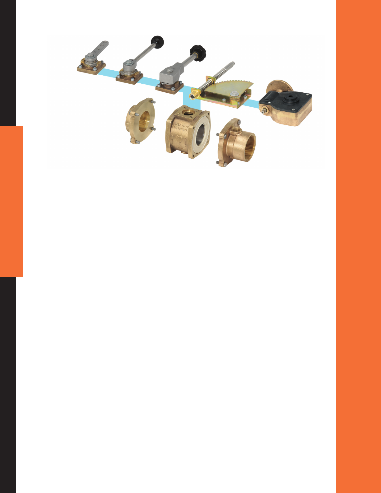
I. INTRODUCTION
Elkhart Brass Unibody apparatus valves are specially designed for reliability, ease of installation and ease
of use.
BALL VALVE
• Unibody Ball Valves are available in 1.5", 2", 2.5", 3", 3.5", and 4" sizes.
• The bodies are constructed of corrosion resistant brass, and the ball is constructed from durable
stainless steel (EB15–EB35) or high strength brass alloy (EB40).
• Dual self-adjusting seats provide bidirectional sealing (EB15-EB35) or single self-adjusting abrasion
resistant unidirectional seat (EB40).
• Adapters (end caps) and pump anges are constructed of either brass or stainless steel requiring no
6
• Swing out construction allows for easy access to internal waterway.
• The patent pending Unibody design allows any actuator assembly to be bolted onto the valve body
• Actuators are interchangeable so that a Unibody Valve may be easily converted to a different actuation
• Durable handles and handle stops ensure dependability, while the handle may be easily changed to
O-rings that could cut or tear during servicing.
without need to break the internal plumbing of the truck.
type without the need to break the waterway.
eight different positions by removing a single bolt.
BUTTERFLY VALVE
• Unibody Buttery Valves are available in 3", 4", 5", 6", and 8" sizes.
• Bidirectional with EPDM seat.
• The buttery valve utilizes either our extreme duty electric actuator or our gear actuator.
Unibody Valves meet or exceed NFPA 1901 Standards.
The electric valve utilizes a three-inch extreme duty motor and gearbox for ultimate reliability.
ELKHART BRASS MANUFACTURING COMPANY, INC
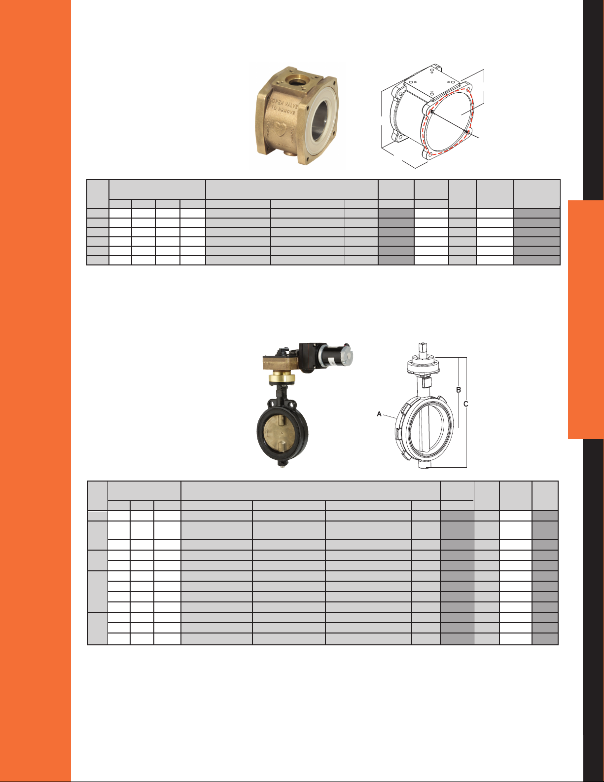
II. COMPONENT IDENTIFICATION
1a. Ball Valve Body
B
B
C
C
D
A
A
DIMENSIONS M ATERIALS BALL RATED CvELKHART Akron
PRESSURE
Size A B C D* Body Ball Seat TYPE (psi) VALUE M O D E L Model
1
1
/
2" 3" 2
2" 3" 2
1
2
/
2" 3
3" 4" 3" 5
1
3
/
2" 4" 3" 5
4" 4" 4
1
/
2" 2
3
/
16" 4
3
/
16" 4
5
/
8" 5
11
/
16" 8
5
1
/
16" 4
/
2" Brass Alloy 844 316 Stainless Steel Hytrel Round 600 139 EB15 7615/7815
5
1
/
16" 4
/
2" Brass Alloy 844 316 Stainless Steel Hytrel Round 600 139 EB20 8620
1
3
/
16" 5
/
8" Brass Alloy 844 316 Stainless Steel Hytrel Round 600 277 EB25 8625
7
1
/
8" 6
/
8" Brass Alloy 844 316 Stainless Steel Hytrel Round 600 510 EB30 8630
7
1
/
8" 6
/
8" Brass Alloy 844 316 Stainless Steel Hytrel Round 600 510 EB35 8635
5
1
/
8" 7
/
8" Brass Alloy 844 316 Stainless Steel Hytrel lat 500 694 EB40 8840
/
/
/
/
* Bolt center diameter
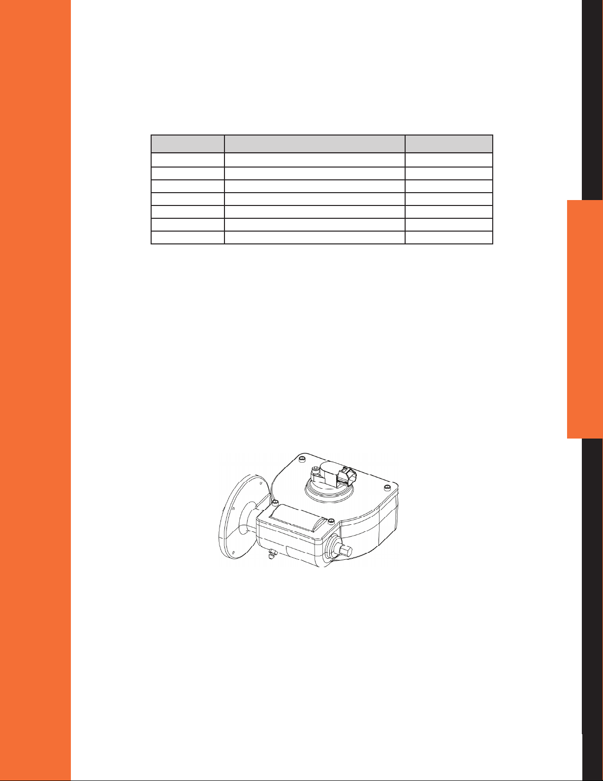
1b. Butterfly Body
8820
8825
8830
8835
7
DIMENSIONS M ATERIALS R ATED CvELKHART Akron
PRESSURE
Size A B C Body W afer Shaft Seat (psi) VALUE M O D E L Model
13
23
3" 1
4"
5"
6"
8" 2
1
2
2
3
2
2
3
2
2
2
2
2
2
/
16" 7
/
16" 8
1
/
8" 8
/
16" 8
1
/
2" 6
/
16" 9
1
/
4" 9
1
/
4" 9
1
/
4" 9
3
/
8" 10
1
/
2" 10
1
/
2" 10
/
32" 11
13
/
32" 12
7
/
16" 13
31
/
32" 13
17
/
32" 13
19
/
32" 14
13
/
32" 11
3
/
16" 15
3
/
16" 15
27
/
32" 17
9
/
16" 18
9
/
16" 18
1
/
8" Cast Iron Aluminum/Bronze 416 Stainless Steel E P D M 250 340 EB3B 7940
15
/
32" Cast Iron Aluminum/Bronze 416 Stainless Steel E P D M 250 660 EB4B 7940/
3
/
8" Carbon Steel 316 Stainless Steel 17-4 PH Stainless Steel PTFE 285 400 EB4J
23
/
32" Cast Iron Aluminum/Bronze 416 Stainless Steel E P D M 250 1080 EB5B 7950
7
/
32" Carbon Steel 316 Stainless Steel 17-4 PH Stainless Steel PTFE 285 650 EB5J
19
/
32" Cast Iron Aluminum/Bronze 416 Stainless Steel E P D M 250 1613 EB6B 7960
13
/
32" Dutile Iron Aluminum/Bronze 416 Stainless Steel E P D M 250 1950 EB6D
1
/
16" Carbon Steel 316 Stainless Steel 17-4 PH Stainless Steel PTFE 285 1050 EB6J
1
/
16" 316 Stainless Steel 316 Stainless Steel 17-4 PH Stainless Steel PTFE 275 1050 EB6JS
11
/
32" Cast Iron Aluminum/Bronze 416 Stainless Steel E P D M 250 3759 EB8B
3
/
16" Carbon Steel 316 Stainless Steel 17-4 PH Stainless Steel PTFE 285 2200 EB8J
3
/
16" 316 Stainless Steel 316 Stainless Steel 17-4 PH Stainless Steel PTFE 275 2200 EB8JS
7945
800.346.0250 • www.elkhartbrass.com
2. Adapters
For complete adapter availability, view the “Unibody Valve Engineering Guide” at www.unibodyvalve.com.
3. Actuators
REMOTEHANDLE
Elkhart Model
Self-Locking Non-Locking
noitpircseDsehcnIsnoisnemiD
8
Handle Length A
(short)
Handle Length A
(long)
Handle Height B 15/
Overall Height C 21/
Overall Height C
DIRECTHANDLE
Handle Length A
(short)
Handle Length A
(long)
Handle Height B 1
Overall Height C 2
Overall Height C
(with slow close)
41/
2"
A
7" Long R2F R4F
Short R1F R3F
C
B
35/
8"
4 esolc wols"
16"
Short with
Long with
R1S R3S
esolc wols)esolc wols htiw(
R2S R4S
noitpircseDsehcnIsnoisnemiD
Elkhart
Mode
5" Short D3F
5
9
/
16"
7
8"
/
1
4"
/
A
C
B
Long D1F
Short with
slow close
Long with
slow close
Short with
5
3
8"
/
chrome cover
Long with
chrome cover
D3S
D1S
D4F
D2F
ELKHART BRASS MANUFACTURING COMPANY, INC
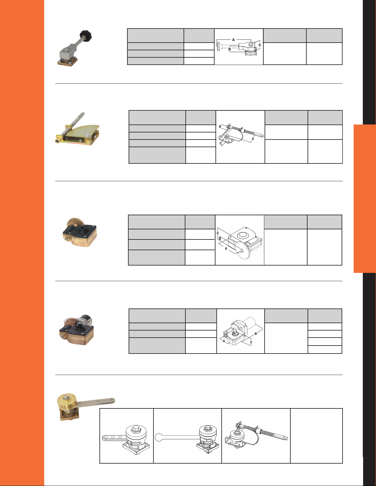
TWISTLOCK
Elkhart
noitpircseDsehcnIsnoisnemiD
Model
Handle Length A 8
15
/
16"
Handle Height B 1
7
/
8 dradnatS" T1F
Overall Height C 3"
B
A
C
Elkhart
noitpircseDsehcnIsnoisnemiD
Model
Handle Length A 8
15
/
16"
Handle Height B 1
7
/
8 dradnatS" T1F
Overall Height C 3"
B
A
C
Elkhart
noitpircseDsehcnIsnoisnemiD
Model
Handle Offset A 4
7
/
8"
Standard S1F
Handle Height B 1
1
/
8"
Overall Height C
1
7
/
8"
Standard with S1S
Overall Height C
3
5
/
16"
slow close
(with slow close)
B
A
C
* For use on the EB6D only.
Elkhart
noitpircseDsehcnIsnoisnemiD
Model
Handle Length A 8
15
/
16"
Handle Height B 1
7
/
8 dradnatS" T1F
Overall Height C 3"
B
A
C
Elkhart
noitpircseDsehcnIsnoisnemiD
Model
Handle Offset A 4
7
/
8"
Standard S1F
Handle Height B 1
1
/
8"
Overall Height C
1
7
/
8"
Standard with S1S
Overall Height C
3
5
/
16"
slow close
(with slow close)
B
A
C
Elkhart
Dimensions Inches Description
Model
Handle Offset A 2
9
/
16"
Handwheels
Handle Height B 1
9
/
16" are ordered G1F
*G2F
Overall Height C 3
7
/
16"
separately.
B
A
C
* For use on the EB6D only.
RACKandSECTOR
Handle Length A 8
Handle Height B 1
Overall Height C 3"
15
16"
/
7
8 dradnatS" T1F
/
A
B
C
noitpircseDsehcnIsnoisnemiD
Elkhart
Model
Handle Offset A 4
Handle Height B 1
Overall Height C
Overall Height C
(with slow close)
GEAR
ELECTRIC
SLOWCLOSE
Dimensions Inches Description
Handle Offset A 2
Handle Height B 1
Overall Height C 3
Manual Offset A 2
Motor Length B 10
Overall Height C (E1F, E2F,
E3F, E4F, E5F, and E6F)
Controllers are ordered separately. * For use on the EB6D only.
7
8"
/
1
8"
/
7
1
8"
/
5
3
16"
/
9
16"
/
9
16" are ordered G1F
/
7
16"
/
9
16"
/
1
4"
/
3
8
4
"
/
noitpircseDsehcnIsnoisnemiD
B
C
A
Standard S1F
Standard with S1S
Elkhart
Model
slow close
Elkhart
Model
C
B
A
Handwheels
separately.
*G2F
9
noitpircseDsehcnIsnoisnemiD
B
A
C
Controllers are
ordered
separately.
Elkhart
Model
E1F
*
E2F
E3F & E4F
*E5F & *E6F
800.346.0250 • www.elkhartbrass.com
Slow close may
be bolted to
remote, direct
and rack and
sector actuators.
4. Remote Valve Controls
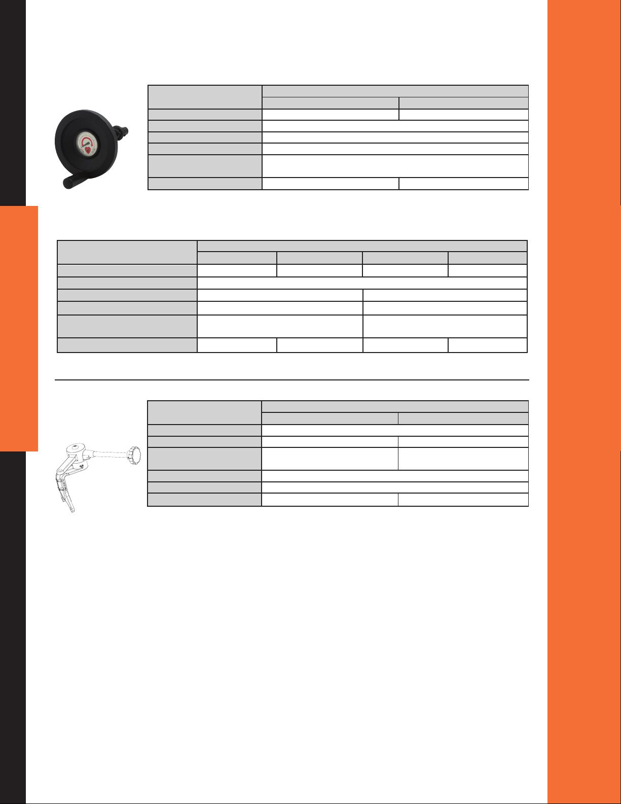
POSITIONINDICATINGHANDWHEEL
MODELS
P 3.6-PWG4-PWGNOITAMROFNI TCUDOR
Handwheel diameter "3.6"4
Material Aluminum
Finish
(specify)
Installation diameter 1.125"
Furnished with
Weight .sbl 5.4.sbl 0.4
swivel joints with protective rubber boots
STANDARDHANDWHEEL
PRODUCT INFORMATION GWR-5 GWR- 6.5 GWD-5 GWD-6.5
Handwheel diameter 5" 6.5" 5" 6.5"
Material Chrome plated brass
Type Panel mount Direct mount
Installation diameter –"521.1
Furnished with
Weight 4. 0 lbs . 6.75 lbs. 2.50 lbs. 5.25 lbs.
Panel bushing and two universal swivel
joints with protective rubber boots
Black or Chrome
Panel bushing and two universal
MODELS
–
10
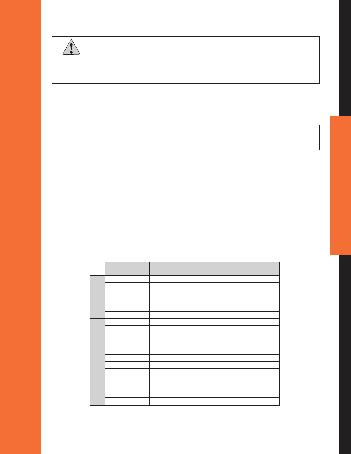
PIGGY-BACK
REMOTE
CONTROLUNIT
MODELS
Valve compatability For use with the Elkhart Brass Unibody line
Handle gnikcol-noNkcoL-tsiwT
Orientation
(specify)
Material Cast brass with stainless steel handle rod
Length "8"8
Weight .sbl 0.6.sbl 0.6
Dual handle right (A) Dual handle right (A)
U3-CRU2-CRNOITAMROFNI TCUDORP
)B( tfel ro)B( tfel ro
ELKHART BRASS MANUFACTURING COMPANY, INC
III. GENERAL WARNINGS AND CAUTIONS
Important:
Beforeinstallingandoperatingthisequipment,readandstudythismanualthoroughly.Proper
installationisessentialtosafeoperation.Inaddition,thefollowingpointsshouldbeadheredtoinorder
toassurethesafetyofequipmentandpersonnel.
• All personnel who may be expected to operate this equipment must be thoroughly trained in its safe
and proper use.
• Become thoroughly familiar with the hydraulic characteristics of this equipment.
NFPA1901Standardsspecifyaminimumof3secondsisrequiredtoopenorclosea3”orlargervalve.
• Always open and close valves slowly to avoid water hammer.
• After each use, and on a scheduled basis, inspect equipment per instructions in the maintenance
Section V.
• Keep ngers and hands clear of moving parts.
• Do not use lubrication on the valve ball or seats.
• Do not wrench on the valve body or the opposite adapters.
• Disconnect power before servicing an electric valve.
• Clear debris from waterway before the valve is installed.
• Foreign materials such as metal chips could jeopardize the sealing capability of the valve. Any drilled
holes required in the plumbing should be added, and the chips removed from the waterway, prior to
installation of the valve.
• Do not exceed rated operating pressure for any valve as listed in Table 1.
11
Model Rated Operating Pressure C
Number (psi) Value
EB15 600 139
EB20 600 139
EB25 250 277
EB30 250 510
Ball Valves
Butterfly
EB35 250 510
EB40 250 694
EB3B 250 340
EB4B 250 660
EB4J 285 400
EB5B 250 1080
EB5J 285 650
EB6B 250 1613
EB6D 250 1950
Valves
EB6J 285 1050
EB6S 275 1050
EB8B 250 3759
EB8J 285 2200
EB8S 275 2200
Table 1 – Pressure
v
800.346.0250 • www.elkhartbrass.com
IV. QUICK INSTALLATION GUIDE
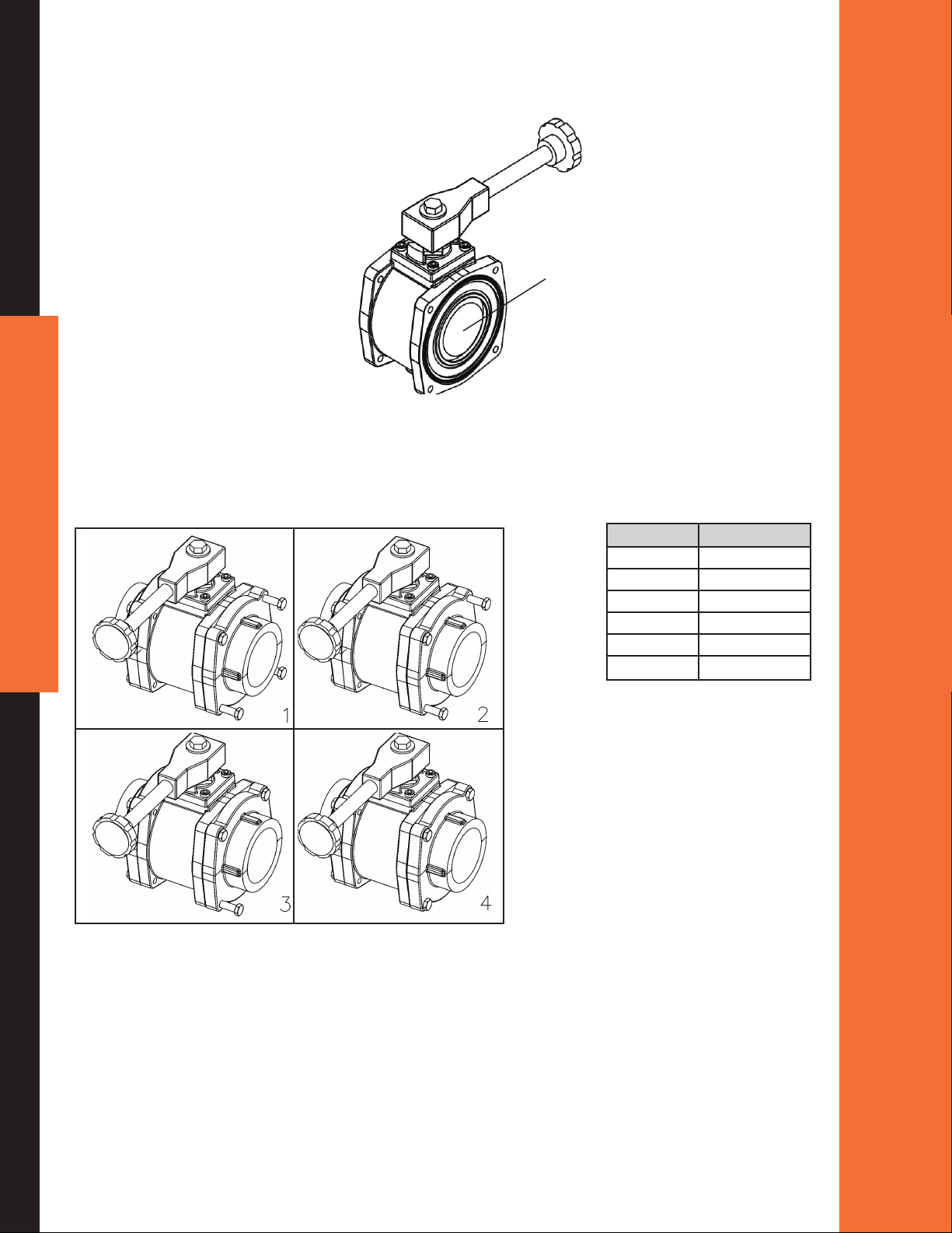
1. Adapters to Valve Body
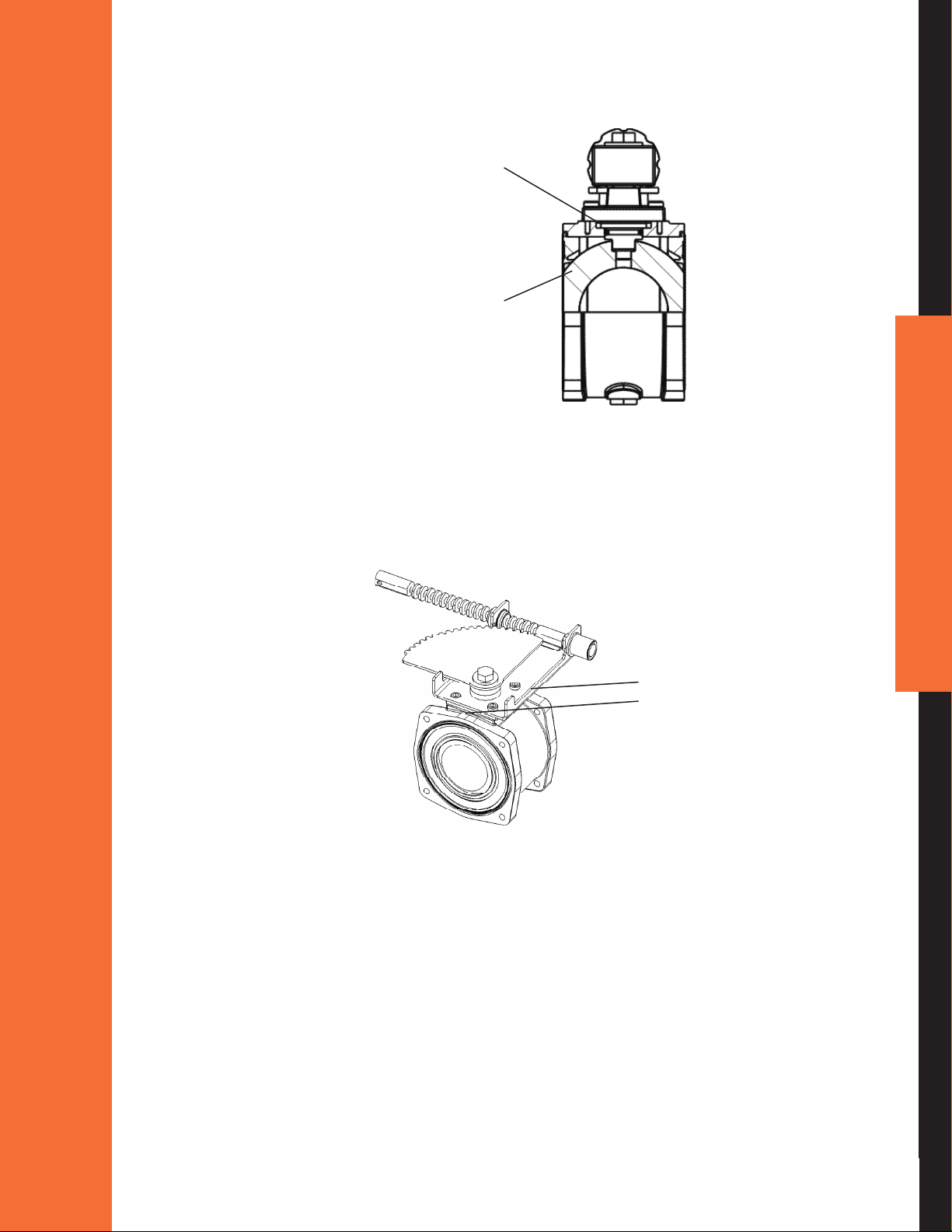
A) Move valve to close position. See Figure 1.
Ball in closed
position
Figure 1
B) Tighten the four 3/8" adapter bolts in an X pattern (see Figure 2). See Table 2 for torque
requirements.
12
Valve Torque
EB15 25-30 ft-lbs
EB20 25-30 ft-lbs
EB25 25-30 ft-lbs
EB30 38-40 ft-lbs
EB35 38-40 ft-lbs
EB40 60-70 ft-lbs
Table 2 – Torque
Figure 2
ELKHART BRASS MANUFACTURING COMPANY, INC
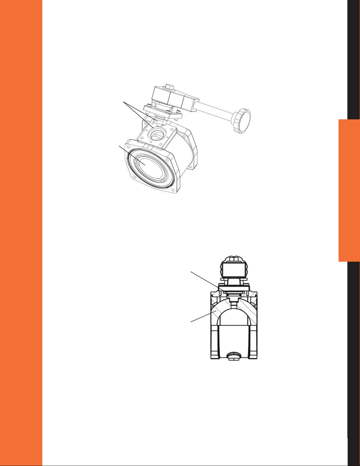
2. Installation of Actuators to Valve Body
A) Remote, Direct Handle, or Twist Lock Actuator
1. Hold the actuator assembly above valve body assembly and align the actuator shaft
with the slot in the ball as shown. See page 18 Handle Position if the handle requires
new orientation.
Actuator shaft
and slot in
ball align
Ball in closed
position
Figure 3
2. Push the actuator assembly down against valve body assembly and rotate the handle
assembly in both directions slightly while pushing assembly against valve body until
actuator drops into slot in valve ball as shown in Figure 4. There should be no gap
between the actuator assembly and the valve body.
No gap between
actuator assembly
and valve body
Ball in closed
position
Figure 4
13
800.346.0250 • www.elkhartbrass.com

3. Rotate the actuator assembly on valve body until handle stops align with waterway
as shown in Figure 5.
Handle stops align
with waterway
Figure 5
4. Fasten the actuator assembly to valve body by tightening 5/16 socket head cap screws in
an X pattern to a torque of 15 ft-lb.
B) Rack and Sector Actuator
1. Hold the actuator assembly above valve body assembly and align the actuator shaft
with the slot in the ball as shown in Figure 6. Ensure that the rst tooth of the rack and
the rst tooth of the section are aligned properly (see Figure 7) or the valve will not
shut completely. Note that the rack and sector actuator assembly can rotate in 90°
increments for different orientations of the actuator assembly.
14
First teeth
together
Actuator shaft
and slot in ball
align
Ball in closed
position
Figure 6 Figure 7
ELKHART BRASS MANUFACTURING COMPANY, INC
2. Push the actuator assembly down against valve body assembly and rotate the assembly
in both directions slightly while pushing assembly against valve body until actuator drops
into slot in valve ball as shown in Figure 8. There should be no gap between the actuator
assembly and the valve body.
No gap between
actuator assembly
and valve body
Ball in closed
position
Figure 8
3. Rotate the actuator assembly on valve body until the rectangular actuator adapter aligns
with the square-mounting surface on the valve body. Ensure the rack is in the proper position when the ball is open, as shown in Figure 9.
Rectangle adapter
aligns with valve
body adapter
Figure 9
4. Fasten the actuator assembly to valve body assembly by tightening 5/16 socket head
cap screws in an X pattern to a torque of 15 ft-lb.
15
800.346.0250 • www.elkhartbrass.com
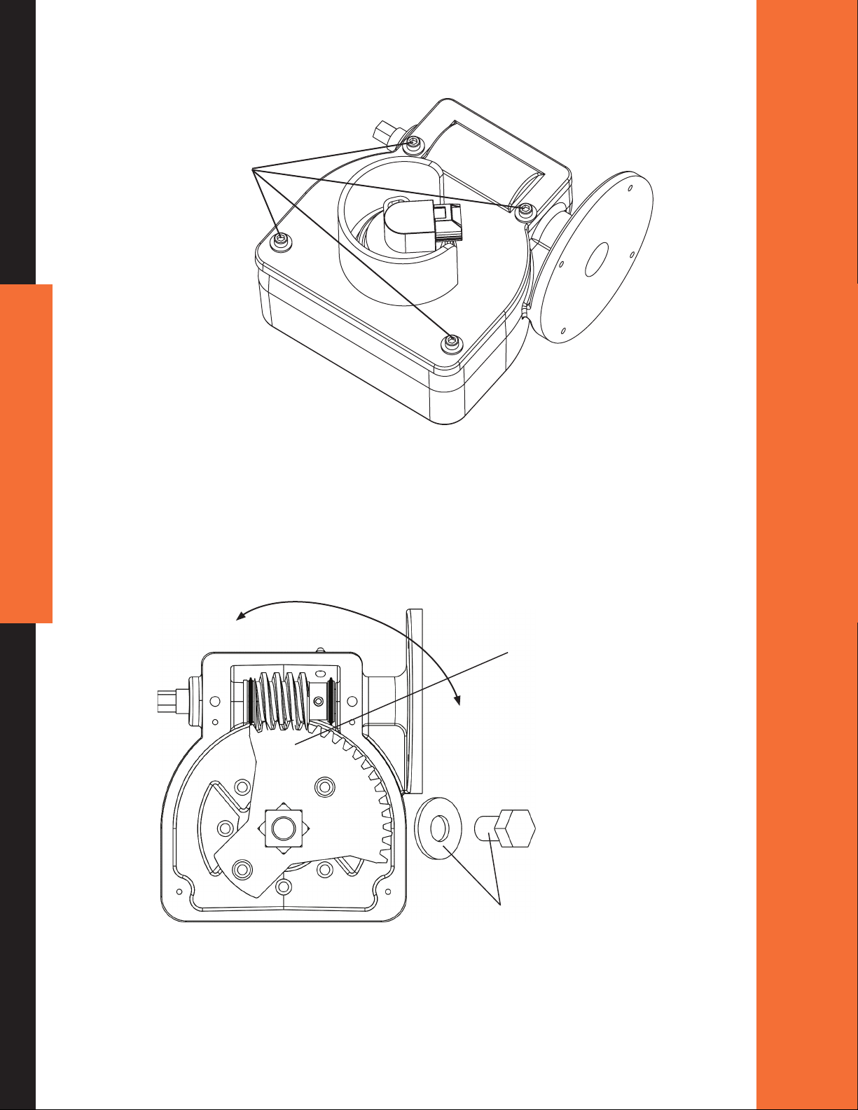
C) Gear and Electric Actuator
1. Disassemble gear case cover from gear case by removing four screws as shown below.
Remove
four
screws
Figure 10
16
2. Remove the 1/2" bolt and washer that locks the actuator assembly in position. Remove
actuator shaft. Remove gear sector and place in the full clockwise position as shown in
Figure 11. This equates to the valve open position for electric actuators on all valves
except EB_J & EB_S buttery valves (The gear sector positions are opposite for the EB_J
and EB_S butterys with electric actuators). This full clockwise position also equates to
the closed position for gear actuators on all valves.
Close(Electric)
Open(GearOP,EB_J&EB_S)
Place gear sector
in full clockwise
position
Open(Electric)
Close(GearOP,EB_J&EB_S)
Figure 11
ELKHART BRASS MANUFACTURING COMPANY, INC
Remove 1/2"
bolt and
washer
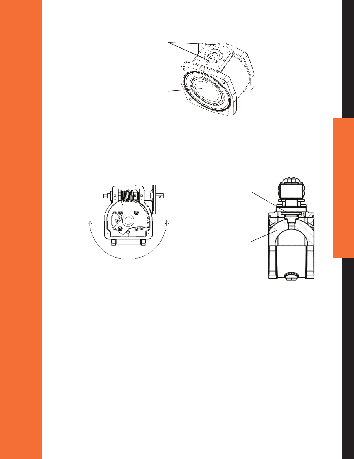
3. Hold the actuator assembly above valve body assembly and align the actuator shaft with
the slot in the ball as shown in Figure 12 for desired gear position on valve body as shown
in Figure 13.
Actuator shaft and
slot in ball align
Ball in closed
position
Figure 12
4. Push the actuator assembly down against valve body assembly and rotate the actuator
assembly in both directions slightly while pushing assembly against valve body until
actuator drops into slot in valve ball as shown in Figure 12. There should be no gap
between the actuator assembly and the valve body as shown below.
No gap between
actuator assembly
and valve body
Ball in closed
position
Figure 13
Figure 14
5. The actuator assembly should be rotated on the valve body until the #10-24 socket head
cap screws line up with the tapped holes on the valve body. The actuator assembly may
be positioned in rotational increments of 45° on the valve body. Replace the 1/2" bolt
and washer that were removed in Step 2. Secure with a thread locker (Blue Loctite #242)
and tighten to 5-7 Ft-Lb.
6. It is recommended to apply a thread locker (Blue Loctite #242) to the screws fastening
the actuator to the valve. Fasten the actuator assembly to valve body assembly by
tightening the #10-24 socket head cap screws in an X pattern to a torque of 5 ft-lb.
17
800.346.0250 • www.elkhartbrass.com
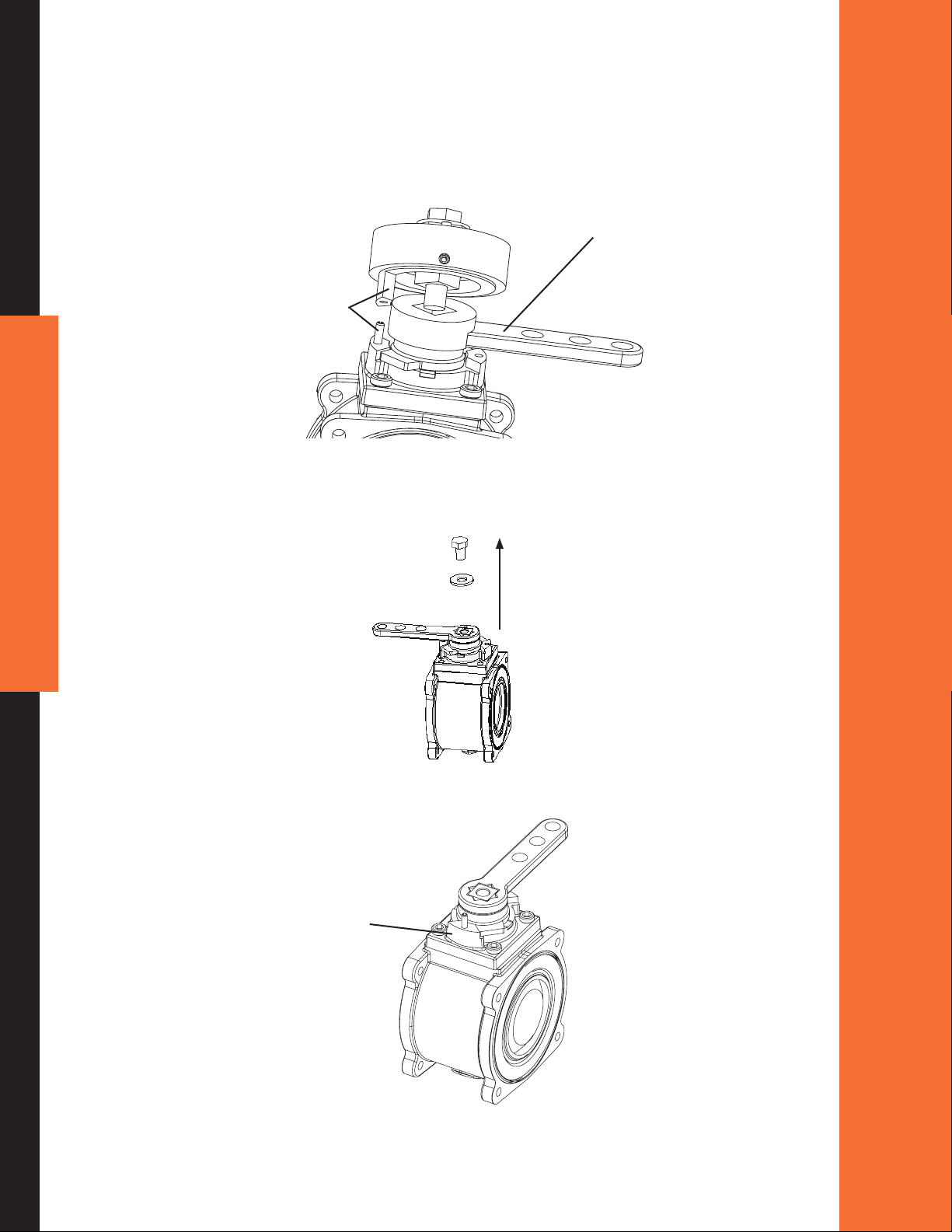
7. On G1F, E3F and E4F assemblies, reattach the gear case cover to the gear case by
replacing the four screws that were removed in Step 1.
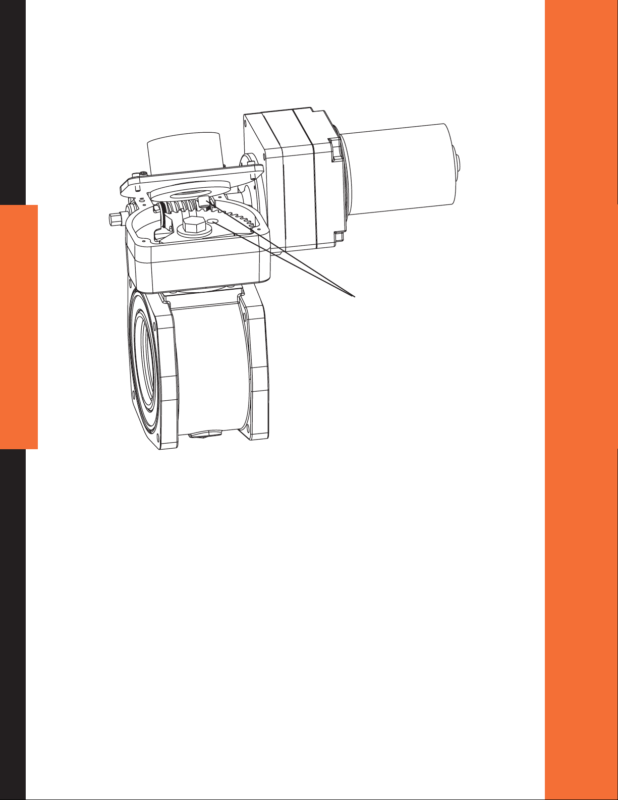
8. On E1F (electric) assemblies only, the gear case cover should be re-attached to the gear
case with the sensor shaft engaged into the gear sector. Accomplish this by aligning the
sensor shaft with the gear sector hole nearest the worm gear as shown below.
Sensor shaft aligns
with gear sector
18
Figure 15
9. Push the gear case cover on to the gear case so that the sensor actuator engages in
the hole on the gear sector, then rotate the gear case cover on the gear case so that
the holes in the gear case cover line up with the tapped holes in the gear case. Next,
re-attach the screws that were removed in Step 1.
3. Handle Position
The twist lock, remote, and direct handle actuators may easily have the handles repositioned in
45° increments. The following details the handle reposition procedure.
ELKHART BRASS MANUFACTURING COMPANY, INC
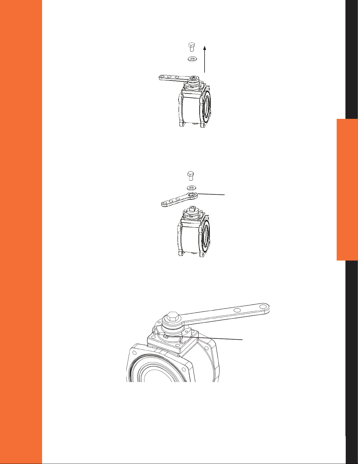
A) Non-Slow Close Handle Positioning
1. Remove the 1/2" bolt and washer that locks the handle in position.
Figure 16
2. The spring-loaded assembly will urge the handle off the actuator shaft. Remove the
handle completely from the shaft and rotate to the desired location in 45° increments.
Remove handle
and rotate in
45° increments
Figure 17
3. Place handle back on actuator shaft in new location and reattach washer and 1/2" bolt.
While tightening bolt, ensure that the stop plate tabs line up with slots in adapter plate
as shown.
Bearing break tab drops
into slot on adaptor plate
19
Figure 18
800.346.0250 • www.elkhartbrass.com
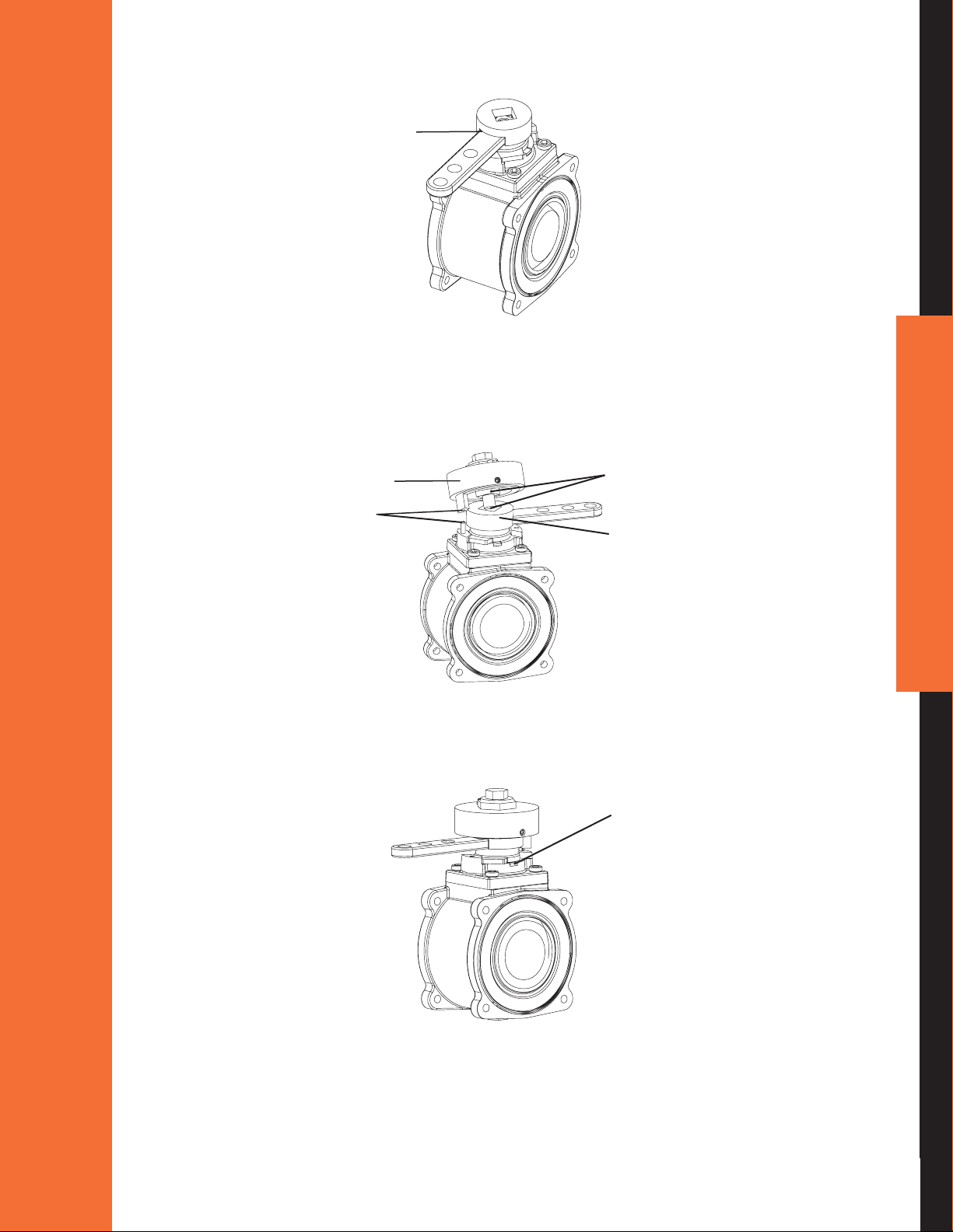
B) Slow Close Handle Positioning
A slow close is available for the R1S, R2S, D1S, D3S and S1S actuators.
1. Properly position the handle. See page 19 - Non-Slow Close Handle Positioning
2. Determine the position of the roll pin alignment. Ensure that the handle will not be
obstructed from moving to full open and full close positions when installed.
Handle moves freely
Pin alignment
Figure 19
20
3. Remove the 1/2" bolt and washer that locks the handle in position.
Figure 20
4. Drive the roll pin into an appropriate stop.
Roll pin
Figure 21
ELKHART BRASS MANUFACTURING COMPANY, INC
5. Place the handle coupler over the handle with the handle lling the slot.
Slot
Figure 22
6. Place the slow close onto the handle coupler. Ensure that the slow close shaft is properly
engaged with the handle coupler. Place entire assembly onto actuator shaft considering
proper handle and drive pin alignment.
Slow Close
Pin Alignment
Shaft Alignment
Handle Coupler
Figure 23
7. Attached washer and new 2" long 1/2" bolt. While tightening bolt, ensure that the bearing
break tabs line up with slots in adapter plate as shown.
Bearing break tab
drops into slot on
adapter plate
21
Figure 24
800.346.0250 • www.elkhartbrass.com
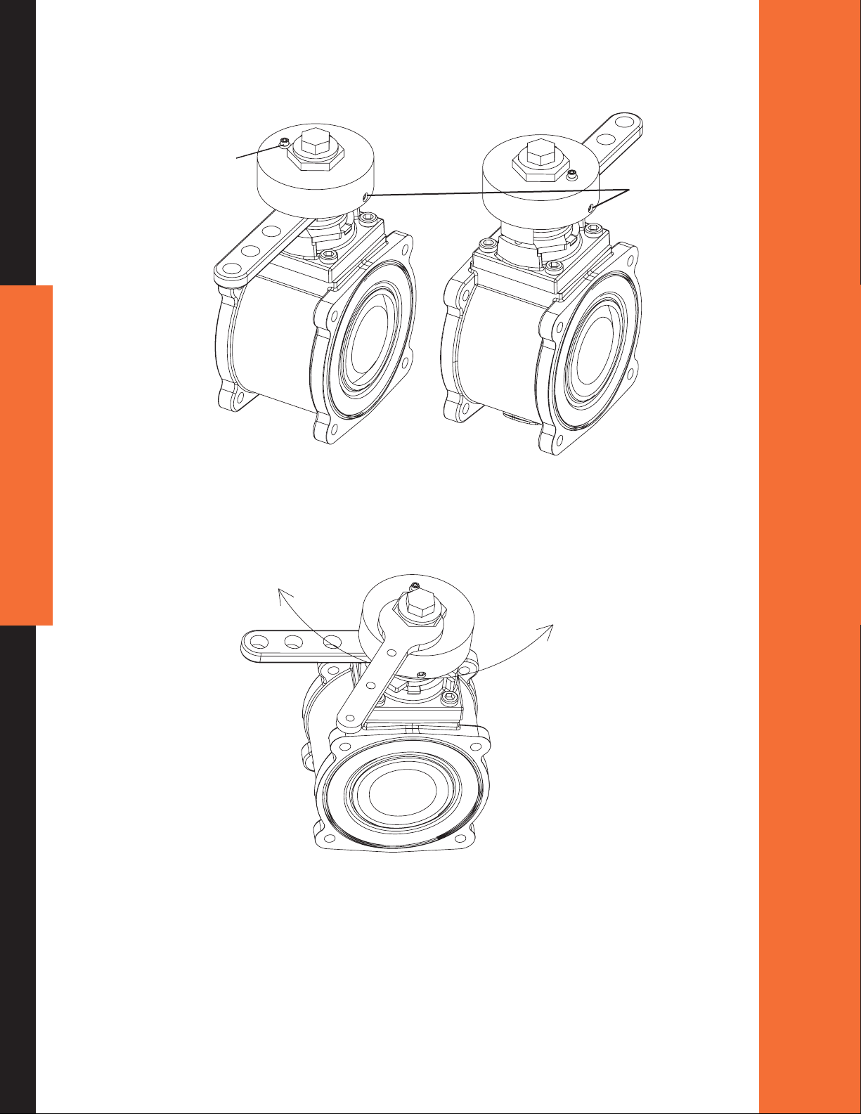
4. Slow Close Adjustment
1. Loosen the socket head cap screw and two set screws.
Cap screw
Figure 25
Set screws
22
2. Use a 1-3/8" wrench to adjust the slow close. (Note that a 3" or larger valve cannot be
actuated to close or open in less than three seconds per NFPA 1901.) Turning the cover
clockwise will reduce the speed at which the valve can be actuated. Turning the cover
counterclockwise will increase the speed at which the valve can be actuated.
Slower
Faster
Figure 26
3. Once proper adjustment has been achieved, tighten the socket head cap screw and both set
screws rmly.
ELKHART BRASS MANUFACTURING COMPANY, INC
V. MAINTENANCE
1. Ball Valve Seal Kits
The Unibody Valve body assemblies require very little maintenance. If it does become necessary
to service a ball valve body, seal kits are available to provide all O-rings and seats required in the
valve assembly.
Additional kits are available that also include the valve ball in the case of severe waterway
debris damage.
Part Number Description Valve Size
02BE ro 51BEtiK laeS00067456
65477000 Seal Kit with Stainless Steel Ball EB15 or EB20
65478000 Seal Kit EB25
65479000 Seal Kit with Stainless Steel Ball EB25
53BE ro 03BEtiK laeS00008456
65481000 Seal Kit with Stainless Steel Ball EB30 or EB35
04BE tiK laeS00028456
Table 3
Swing out instructions for accessing internal waterway.
1. Remove three of the end-cap bolts on each side of the valve away from the desired
swing-out direction.
2. Loosen the remaining two bolts (one on each side of the valve).
3. Rotate the valve out from the end caps pivoting on the remaining two end cap bolts.
4. After servicing the valve, ensure the two seats are secured in the valve body. Rotate the valve back
in line with the end caps.
5. Replace all the end cap bolts and tighten in an X pattern to the torque specied in Table 2 (page 12).
Do not lubricate the valve ball or seats.
2. Gear Box Lubrication
Gearbox should be greased with petroleum base grease (Mobilux EP2) every six months.
Figure 27
23
800.346.0250 • www.elkhartbrass.com
 Loading...