

Page 1
SCORPION
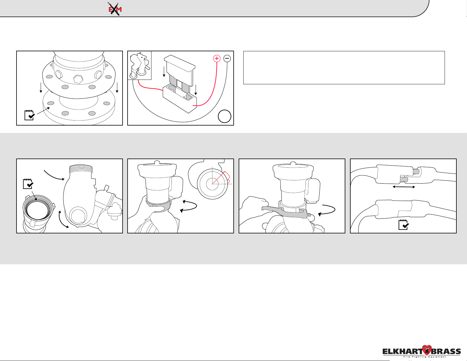
1.
A. Install monitor to flange using 5/8”-11
UNC Grade 5 bolts and nuts. Tighten
uniformly to 70ft/lb using Loctite 242 or
equivalent.
Gasket or
Sealant
2.
A. Position monitor discharge elbow
vertical. Ensure gasket is inside nozzle
swivel before installing.
180°
Typical Aerial Platform Install Guide:
B. Add a 20A(12VDC)* fuse between
RED controller lead and positive power
lead. Use 40A fuse if nozzle with foam
expansion tube is utilized.
B. Hand tighten nozzle to monitor using
swivel end piece. Position actuator
assembly about 45° around the swivel.
*10A(24VDC)
16g
0°
45°
NOTE: We recommend using 14 AWG for monitor power and ground (12
AWG if using nozzle with foam expansion tube). See Scorpion EXM
monitor installation guide on page 9 of the manual for length to gauge
recommendations.
C. Tighten swivel using a spanner
wrench to ensure a secure connection.
Monitor & Nozzle
MONITOR
D. Connect nozzle and monitor two-way
connectors.
1
NOZZLE
3.
Confirm that all connections are tight and all electrical connections have been reconnected. If installing additional components, such as controllers, you may choose to
double check the connections after everything has been installed.
98342040 Rev. Rel
Page 2
SCORPION
Typical Aerial Platform Install Guide:
Control Components/Accessories
2
- Panel Mount Controller Handheld Controller / Docking Station
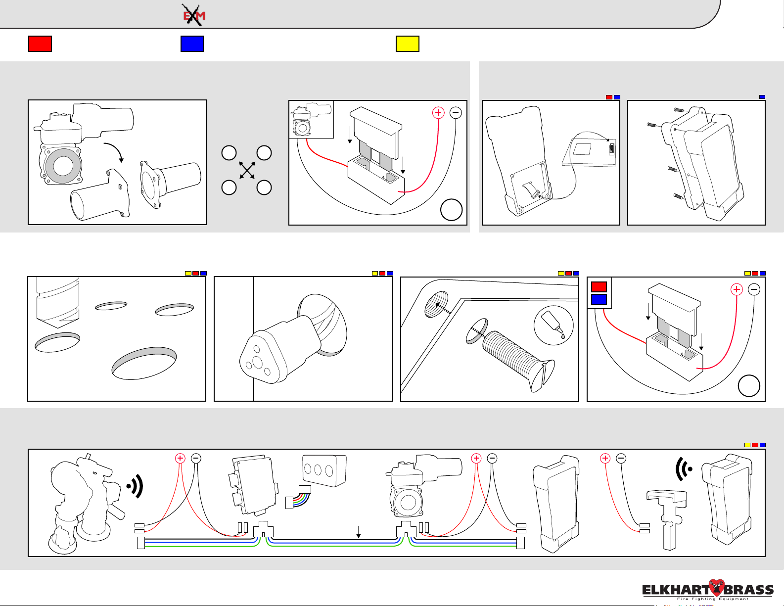
A. Install valve into plumbing. Torque
4.
adapter bolts to spec using torque specs
listed to the right.
A. Follow mounting templates on page
5.
30 of the instruction manual for hole
diameters and dimensions.
-
B. Add a 30A(12VDC)* fuse between
RED controller lead and positive power
lead.
*15A(24VDC)
Tighten Adapter
Bolts using a
cross pattern
1 3
4 2
EB40:
60-70 ft-lbs
B. Drill holes for CAN network and
power cables for each components’
leads behind each component.
- OEM Interface Module
RF Installation - The RF
Module will be upside down
when installed correctly.
16g
C. Mount components to panel using
10-24 x 1/2” screws. Use Loctite 242 or
equivalent.
Connect power and attach
battery pack to Handheld
controller.
D. Add a 1A (12VDC)* fuse between
red component lead and positive power
*.5A (24VDC)
lead.
7/32” dia.
unless noted
A. Connect entire CAN network together using 18-22 AWG. Ensure every component connected to the CAN network is connected in between 2 end components that
6.
have CAN termination. Please refer to the BLUE, GREEN, and BLACK lines as the CAN wires below.
CAN
Network
Wires
Before continuing please follow the steps on page 14 of the Scorpion EXM instruction manual, outlining the
EXM Configuration Tool.
98342040 Rev. Rel
18g
Page 3

AUX
OSC
OPEN
CLOSE
OSC
FOG
CLOSE
OPEN
CLOSE
SCORPION
NOTE: You will
need to calibrate
the valve before
use. While you
are NOT in
setup mode,
press and hold
<Preset> and
<Close> for
approximately 5
seconds. The
valve will
a u t o m a t i c a l l y
start to calibrate
itself.
The following
steps are
optional (O).
Pressing the
<Osc> button will
cycle through the
monitor speed
options:
LEDs - Ver / Hor
0 - Fast / Fast
1 - Slow / Fast
2 - Fast / Slow
3 - Slow / Slow
Move monitor to
desired position,
then press <Fog>
and <Osc> at the
same time to
store a stow
position.
Stow position
must be within
allowed limits of
travel.
CALIBRATE VALVE
PRESET
SET MONITOR SPEED
(O)
3
SET STOW POSITION
(O)
Typical Aerial Platform Install Guide:
Press and hold
<Stream> and
<Fog> until
yellow status
LED on controller
and blue status
LED on monitor
box turn on.
From a Joystick
OPEN
Controller, press
and hold <Aux>
and <Preset>
until LEDs turn
on.
Move monitor to
the left limit and
press <Close>.
Move monitor to
the right limit and
press <Open>.
Maximum Travel
limits will give
approx 175° of
travel from the
c a l i b r a t e d
horizontal forward
position in either
direction.
Pressing <Open>
and <Close> at
the same time
will clear travel
limits, keep out
areas, and the
stow position.
4 5
STATUS POWER
L
CLEAR ALL
C
E
L
PRESET
A
R
A
L
L
Setup Mode
This step is
required (R).
Aim monitor at
center forward
“zero” position.
Hold <Preset>,
then press and
hold <Left> or
<Right> until
status LED on
monitor blinks &
returns to solid.
Takes about a
second.
Lower Left:
Move to top/right
corner of the
lower left zone,
hold <Preset>,
press <Close>,
and release both.
Lower Right:
R
Move to top/left
corner of the
lower right zone,
hold <Preset>,
press, <Open>,
and release both.
Press and hold
<Stream> and
<Fog> on the
panel mount and
<Aux> and
<Preset> on the
joystick until the
status LEDs turn
off.
CALIBRATE HORIZONTALENTER SETUP MODE
(R)(R)
21
SET KEEP-OUT ZONESSET TRAVEL LIMITS
(O)(O)
Lower Right
Zone:
Top left corner
Lower Left
Zone
0°
EXIT SETUP MODE
STATUS POWER
8
OPEN
Lower Left Zone:
Top right corner
Right Travel LimitLeft Travel Limit
Lower Right
Zone
3
6
7
98342040 Rev. Rel
Page 4

SCORPION
Button Press Logic: Panel Mount & Handheld Panel Mount Layout:
To Stow
Hold <Fog> and <Osc> until monitor begins to stow.
Typical Aerial Platform Install Guide:
Button Press Logic
4
To Oscillate
Press the <Osc> button at both extremities of the desired oscillation
pattern.
Horizontally Vertically Two Axis Oscillation
NOTE: You can manually control nozzle position while in a single
axis oscillation. Example: Up and Down will allow you to manually
control the vertical axis while in a horizontal oscillation. Any
direction in a two axis oscillation will stop the oscillation.
Left, Right, Up, Down
These function normally
Fog & Straight Stream
These function normally
Valve Open & Close
These function normally
Valve Preset
Opens or closes valve to a predetermined position
Power LED
OSC
USB Port (Covered)
Status LED
FOG
Straight Stream
Monitor Directional
Control Buttons
AUX
Valve Position LEDs
Open
To Change Valve Preset
Open or close the valve to the desired position. Press and hold the
<Preset> button until the preset light blinks (approx 10 seconds).
Valve Auto Travel
To auto travel OPEN, hold the <Open> button, then press <Close>, and
release both. The valve should fully open automatically. To CLOSE,
hold the <Close> button, then press <Open>, and release both.
BUTTON LOGIC
Preset
Close
PANEL MOUNT
98342040 Rev. Rel
 Loading...