

Page 1
E
LLKKHHAARRTT
E
1302 WEST BEARDSLEY AVENUE • P.O. BOX 1127 • ELKHART IN 46515 • (574) 295-8330 • FAX (574) 293-9914
B
RRAASSSS
B
M
M
G
FFG
.
.
O
C
O
C
..,
,
I
I
C
NNC
.
.
Operating and Maintenance Instructions
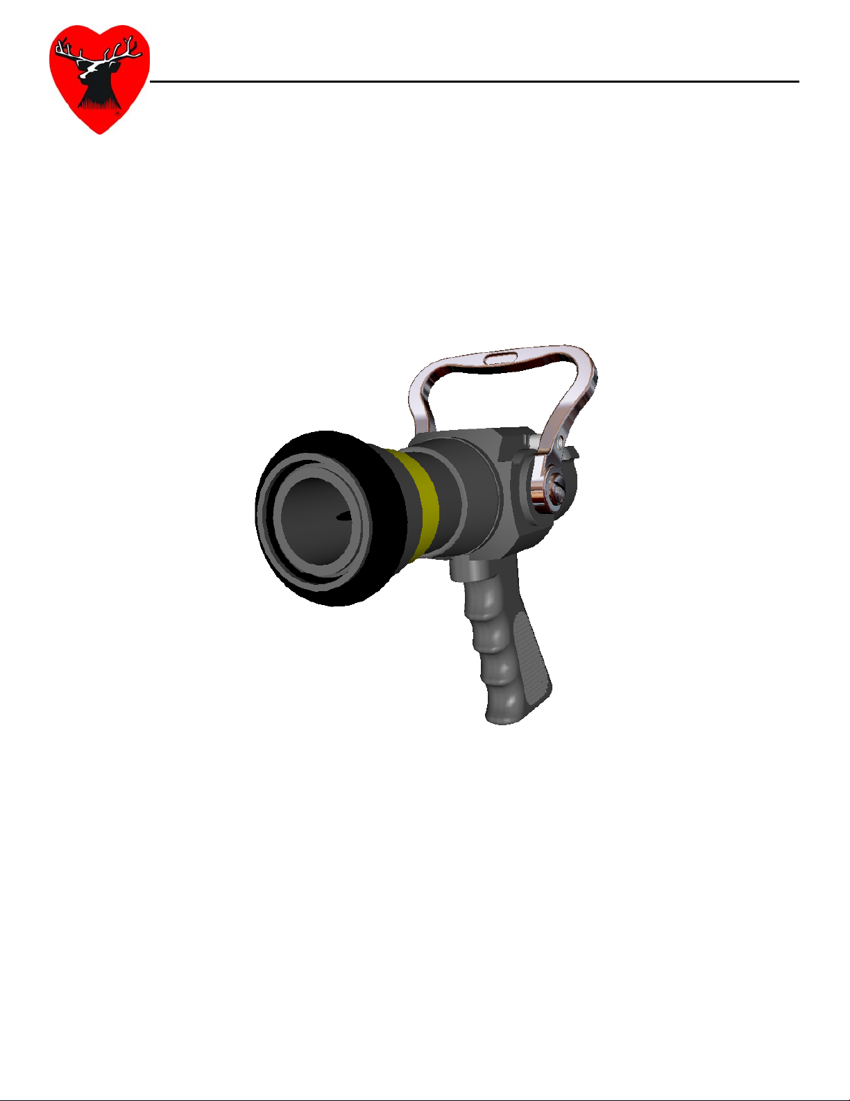
Solid Strike® – Adjustable Solid Stream Nozzle
Catalog Number: SS-475GAAT
Part Number: 00475001 REV REL
98477000 – REV. A
Page 2

Contents
I. Product Safety Information ......................................................................................................................... 1
II. Product Description ...................................................................................................................................... 2
A. Shutoff ........................................................................................................................................................ 2
B. Nozzle Tip .................................................................................................................................................. 2
C. Variable Orifice Waterway ...................................................................................................................... 2
III. Solid Strike® Operation ............................................................................................................................. 3
A. Discharge Adjustment ............................................................................................................................. 3
IV. Maintenance ............................................................................................................................................... 4
A. Inspections ................................................................................................................................................ 4
B. Maintenance After Use ............................................................................................................................ 4
C. Storage....................................................................................................................................................... 4
Page 3

Page 4

I. PRODUCT SAFETY INFORMATION
Important:
Before installing and operating this equipment, read & study this manual thoroughly. Proper use
is essential to safe operation. In addition, the following points should be adhered to in order to
ensure safety:
• All personnel who may be expected to use this equipment must be thoroughly trained in its
safe and proper use.
• Before flowing water from this device, check that all personnel (fire service and civilian) are out
of the stream path. Also, check to make sure stream direction will not cause avoidable
property damage.
• Become thoroughly familiar with the hydraulic characteristics of this equipment, and the
pumping system used to supply it. To produce effective fire streams operating personnel must
be properly trained.
• Open water valve supplying this equipment slowly, so that piping and hose lines fill slowly, thus
preventing possible water hammer occurrence.
• After each use, and on a scheduled basis, inspect equipment per instructions in section VII.
• This nozzle is not designed to be used as a battering ram, sledge hammer, or forcible entry
tool.
• The maximum recommended operating pressure for this nozzle is 100 psi.
Important:
Prior to entering the fire building or any other area considered to be Immediately Dangerous to
Life and Health (IDHL), where firefighter safety will be dependent upon the nozzle and hose line,
the following checks and actions must be made:
- Make sure the hose line is charged and properly pressurized
- Make sure that all kinks are removed from the hose line
- Briefly open and flow nozzle to remove air from hose line and assure proper nozzle function
98477000 Rev. A
Page 5

II. PRODUCT DESCRIPTION
The Solid Strike® Nozzle has been designed primarily to give a fire-fighter a distinct advantage.
The patent pending variable orifice waterway allows the fire-fighter to adjust discharge sizes
without shutting down, depending on the requirements of the specific situation. The nozzle
has been designed to flow a concentrated stream of water.
A. Shutoff
The shutoff portion of the Solid Strike® nozzle features a stream-converging stem that, when
pushed forward by the handle, fully closes the water orifice. The nozzle is manufactured
standard with a 1.5” NH thread free swivel inlet and an aluminum/bronze horseshoe shutoff
handle. A Teflon® impregnated, hard anodized aluminum pistol grip is also standard on the
shutoff body. Special thread and handle configurations can be addressed upon request.
B. Nozzle Tip
The Solid Strike® nozzle tip is constructed from Teflon® impregnated, hard anodized aluminum
and comes standard with an advantage over other nozzles. The nozzle tip includes a male
hose thread at the discharge end to allow either the attachment of an optional fog tip, or
extension of the hose line length, with the Solid Strike® becoming an inline shutoff valve. A
twist-shutoff fog tip could then serve as the fire attack nozzle.
A built in thread protector prevents damage to the male hose thread. To expose the hose
thread, simply rotate the thread protector counter clockwise (as viewed from the inlet end of
the nozzle), then pull back. Included is a set of colored, reflective labels for convenient
discharge line identification. See instructions sheet in label packet for details on label
installation.
C. Variable Orifice Waterway
The patent pending variable orifice waterway enables the user to vary the nozzle discharge
size in response to varying needs. The variable orifice waterway allows for the operator to use
the correct setting depending on the situation. Detents on the handle indicate different orifice
sizes helping the operator know the amount of water being flowed. The variable orifice also
allows the operator to increase the pressure of the water as it exits the nozzle allowing for
concentrated and controlled strikes as well as deeper penetration. The detents mark stream
diameters of 3/4”, 7/8”, and 1”.
Orifice Size (inches) Flow Rate (GPM) @ 50 psi
3/4 118
7/8 159
1 209
98477000 Rev. A
Page 6

®
III. SOLID STRIKE
OPERATION
A. Discharge Adjustment
The discharge size of the nozzle can be adjusted by simply pushing or pulling the handle of the
nozzle towards and away from the operator. The adjustment of the discharge size can be
accomplished without shutting the nozzle down. Pushing the handle forward will decrease the
discharge diameter. Pulling the handle toward the operator will increase the discharge
diameter. Spring-loaded ball detents are used to indicate discharge positions.
Important:
All users should become thoroughly familiar with the hydraulic characteristics of this equipment, and
the pumping system used to supply it. Personnel must be properly trained in all aspects of the nozzle
in order to produce effective fire fighting streams.
Warning:
The reaction force of this nozzle is dependent on the pressure and flow that is supplied to the nozzle.
Excess nozzle pressure may create an unsafe reaction force for the user. The nozzle reaction
formula for water is as follows:
NR = 1.5*d2*NP
NR = Nozzle Reaction (Pounds)
D = Nozzle Diameter (Inches)
NP = Nozzle Pressure (psi) (measured with pitot tube)
98477000 Rev. A
Page 7

IV. MAINTENANCE
The following maintenance procedures should be followed in order to reduce to possibility of
field difficulty or failure.
A. Inspections
Weekly visual inspections and monthly operational checks will promote proper nozzle function.
These inspections should be done daily in busy companies. All nozzles should be flow tested
before entering any hazardous environment to ensure equipment is operating properly.
B. Maintenance After Use
The nozzle should be flushed thoroughly after every use. This can be done by flowing a clean
water source through the nozzle. The internal passageway of the nozzle should also be
visually inspected for possible damage caused by foreign objects carried by the water through
the nozzle.
C. Storage
To prevent possible freeze damage during response, be sure nozzle is thoroughly drained
prior to placing back on apparatus.
Important:
If there is a question regarding any necessary repair or damage issue, contact Elkhart Brass for
assistance.
Phone #: 800-346-0250
Email: info@elkhartbrass.com
98477000 Rev. A
Page 8

ELKHART BRASS MFG. CO., INC.
P.O. Box 1127 · 1302 West Beardsley Ave.
Elkhart, Indiana 46515
E-mail: info@elkhartbrass.com
Website: www.elkhartbrass.com
(800) 346-0250
98477000 Rev. A
 Loading...