

Page 1
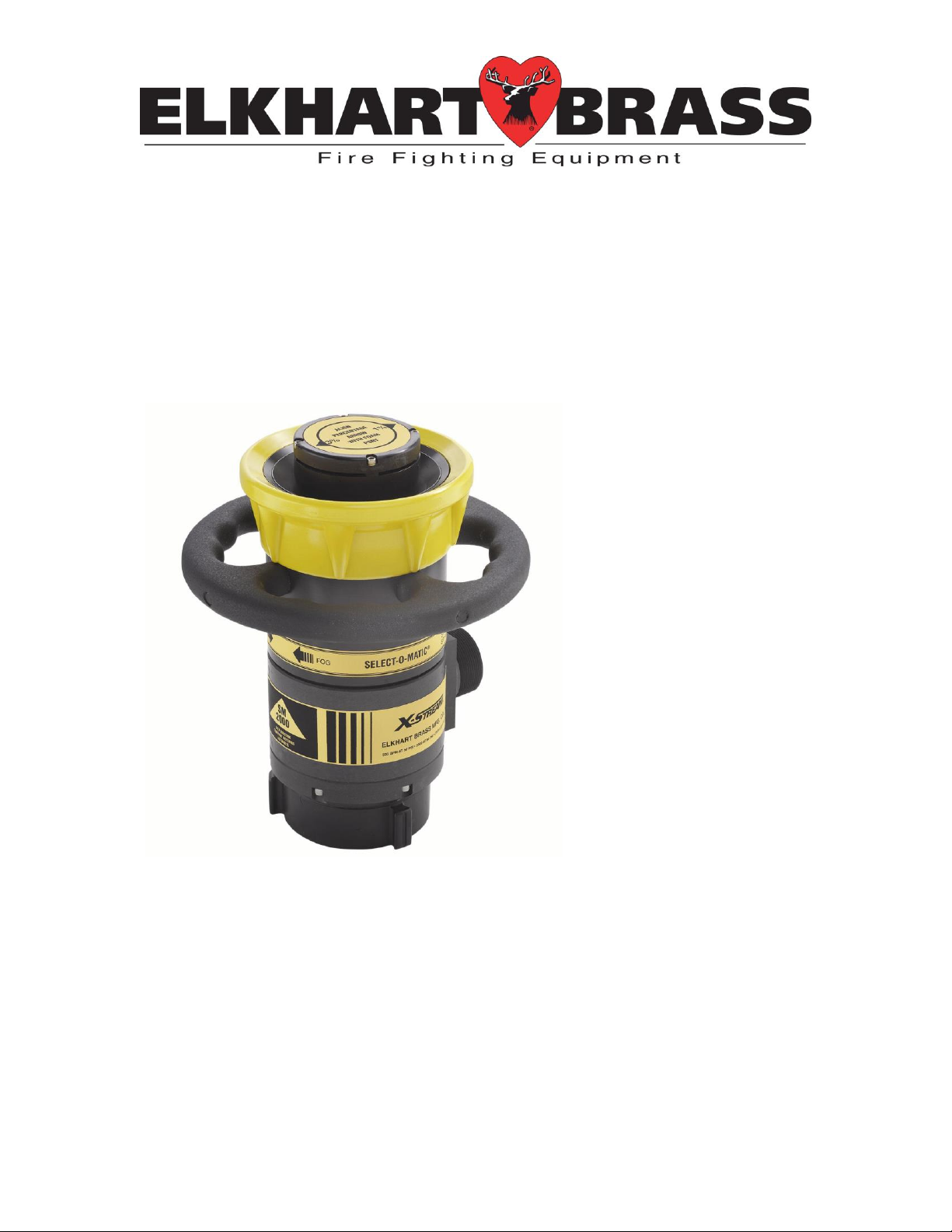
Self-Educting
Master Stream Foam Nozzles
SM-1000-HF
SM-1000E-HF
SM-2000-HF
SM-2000E-HF
98445000 Rev. A
Page 2

Table of Contents
I. Product Safety ........................................................................... 1
II. Installation ................................................................................. 2
III. Nozzle Operation .................................................................... 2
A) SM-1000-HF, SM-1000E-HF, SM-2000-HF, and SM-2000E-HF Master
Stream Nozzles ............................................................................................................... 2
1. Proportioning Rate ............................................................................................. 3
2. Pattern Control ................................................................................................... 3
IV. Maintenance ........................................................................... 5
A) Cleaning ................................................................................................................. 5
B) Pilot Assembly ........................................................................................................ 5
C) Storage .................................................................................................................... 6
D) General ................................................................................................................... 6
Page 3

I. Product Safety
Important:
Before installing and operating this equipment, read & study this manual
thoroughly. In addition, the following points should be adhered to ensure
the safety of equipment and personnel:
1. All personnel who may be expected to use this equipment
must be thoroughly trained in its safe and proper use.
2. Before flowing water from this device, check that all
personnel (fire service and civilian) are out of the stream
path. Also, check to make sure stream direction will not
cause avoidable property damage.
3. Become thoroughly familiar with the hydraulic characteristics
of this equipment and the pumping system used to supply it.
To produce effective fire streams, operating personnel must
be properly trained.
4. Whenever possible, this equipment should be operated from
a remote location. Do not needlessly expose personnel to
dangerous fire conditions.
5. Never attempt to view or change the SM-1000-HF, SM1000E-HF, SM-2000-HF, or SM-2000E-HF foam nozzle
proportioning rate settings while the nozzle is in operation.
6. The nozzle must be properly mated and tightened. Failure
to do so could result in leaks or may cause injury or death.
7. After each use and on a scheduled basis, inspect equipment
per Maintenance on page 5 instructions.
1
Page 4

II. Installation
SM-1000-HF/SM-1000E-HF
SM-2000-HF/SM-2000E-HF
Inlet:
Water: 2-½” NH
Foam: 1-½” NPT
Water: 3-½” NH
Foam: 2” NPT
Flow:
250-1000 GPM Automatic
500-2000 GPM Automatic
Operating
Pressure:
100 PSI
100 PSI
Proportioning
Rate:
1% / 3% Selectable
1%
Pick up Hose:
1-½” diameter x 8’ long
2” diameter x 8’ long
Figure 1 - SM-1000-HF
NOTE: The 55 gallon drum of foam concentrate should be positioned as
close to the monitor as possible without interfering with the desired travel
of the monitor.
1. Attach the nozzle to the monitor discharge. Hand tighten with the foam
inlet nipple down.
2. Remove the small bung hole plug from the 55 gallon drum & install the
vacuum breather. Use Teflon tape or pipe thread sealant to seal the
threads.
3. Remove the large bung hole plug and install the pickup tube. Use Teflon
tape to seal the threads. Tighten so that the 2.0 threaded connection at
the top is pointed at the nozzle.
4. Make sure the rubber gaskets are in place before connecting one end of
the pickup hose to the nipple on the nozzle, and the other to the male
thread on the pickup tube. Tighten both connections.
5. Tighten the nozzle onto the monitors discharge using a spanner wrench.
III. Nozzle Operation
A) SM-1000-HF, SM-1000E-HF, SM-2000-HF, and SM-2000E-HF
Master Stream Nozzles
2
Page 5

1. Proportioning Rate
Handle
Straight
Stream
Fog
Flood Plate/Baffle
Head Assembly
Foam Inlet Port
As shown, this
is set to 1%.
1%
3%
The proportioning rate on the SM-1000-HF and SM-1000E-HF can
only be adjusted or viewed when the water supply valve is close.
1. Firmly grasp the flood plate/baffle head assembly.
2. Rotate until the desired proportioning rate arrow is pointing at
the foam inlet port. See Figure .
3. Listen for audible click noise indicating that the nozzle is in the
detented position.
Note: It may be necessary to use a strap wrench in order to rotate
the assembly into place. Use care to avoid damage to the nozzle.
Figure 2
2. Pattern Control
Manual
1. Grasp the handle firmly.
2. Rotate clockwise for straight stream. Rotate counter-clockwise
for full fog. The full stroke of the pattern requires 180° of input
rotation.
Figure 3
3
Page 6

Electrical
12 VDC
Motor
Male Contact
Female Contact
The SM-1000E-HF and SM-2000E-HF nozzle uses a 11-15 VDC/1-2
Amp motor to adjust pattern control. Positive power to the male
contact with respect to the female contact will generate a fog pattern.
Positive power to the female contact will generate a straight stream.
Figure 4
4
Page 7

Screws
Flood Plate
Baffle Head
Assembly
Pilot Valve Port
Piston Head
Pilot Valve
Spring Adjustment Nut
IV. Maintenance
A) Cleaning
The nozzle should be flushed thoroughly after each use. This is
accomplished by flowing the nozzle with a clean water source for both
water and foam inlets. Ensure the nozzle is set to the largest
proportioning rate.
B) Pilot Assembly
Caution:
Do not allow the piston head and baffle head to turn. If necessary, use a
strap wrench to secure it while moving the pilot valve assembly.
Figure 5 - Pilot Valve Assembly
1. Using a 5/
plate.
2. With the aid of a pair of channel lock pliers, remove the pilot valve
assembly by turning it counter clockwise.
3. Using an air nozzle and pressurized air source, blow through the holes
in the spring adjustment nut to remove any small debris.
” Allen wrench, remove the four screws that retain the flood
32
5
Page 8

4. Submerge the pilot valve assembly in warm soapy water. While
submerged, depress and release the spring-loaded pilot several times.
Do this by inserting a ¼” wood dowel (or plastic end of a pen) into the
open end of the pilot guide stem.
5. Remove the assembly from the soapy water. Using an air nozzle and
a pressurized air source, blow air through the holes in the spring
adjustment nut to remove any debris.
6. Apply a light coating of grease to the pilot valve assembly threads and
stem.
7. Re-insert the pilot valve assembly making sure that the o-ring in the
back of the baffle head is aligned with the pilot valve port in the piston
head. Screw the pilot valve assembly in clockwise by hand until it is
firmly tight.
8. Apply a drop of Loc-Tite removable thread locker to each retaining
screw. Insert the screws through the holes in the flood plate and into
the baffle-head. Tighten the screws firmly using the 5/32” Allen wrench.
C) Storage
After use, the nozzle should always be stored so that the tip is pointed
downward. This will allow the water to drain from the nozzle.
D) General
On a monthly basis, operate the pattern control through a full range of
motion from full fog to straight stream.
If required, apply a light coating of lithium grease to the nozzle body in
the area where it contacts the pattern control sleeve.
Inspect and clean the pilot assembly as outlined in Section IV
Maintenance B) Pilot Assembly. Do this quarterly or as dictated by
water conditions and frequency of use.
Periodically check that fittings are leak free and replace gaskets as
required.
6
Page 9

Notes:
___________________________________________
___________________________________________
___________________________________________
___________________________________________
___________________________________________
___________________________________________
___________________________________________
___________________________________________
___________________________________________
___________________________________________
___________________________________________
___________________________________________
___________________________________________
Page 10

Elkhart Brass Mfg. Co., Inc.
Mailing Address:
P.O. Box 1127
Elkhart, IN 46515 USA
Shipping Address:
1302 W. Beardsley Ave.
Elkhart, IN 46514 USA
Tel. 1-574-295-8330
1-800-346-0250
Fax 1-574-293-9914
e-mail: info@elkhartbrass.com
www.elkhartbrass.com
 Loading...