

Page 1
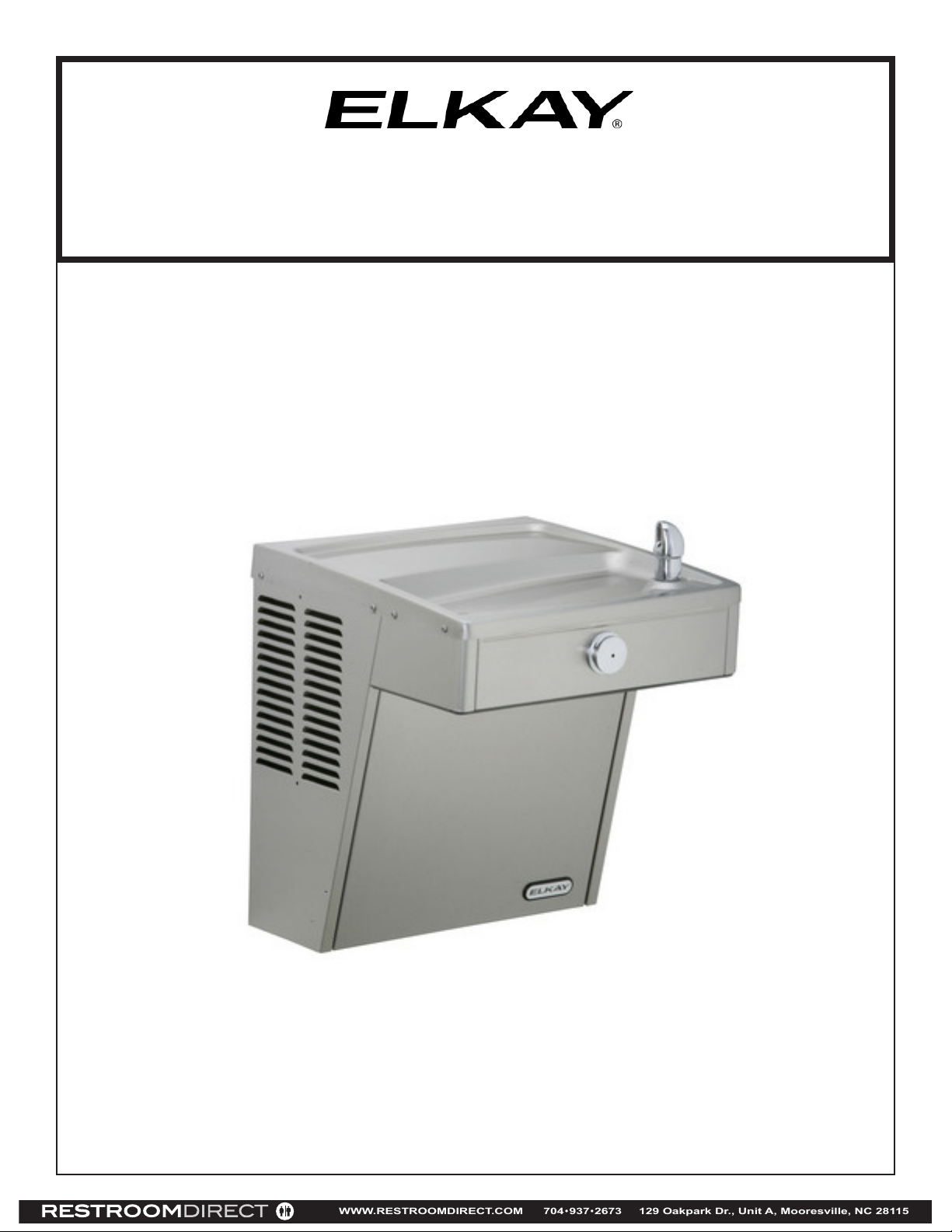
VRC8FR*1C VRCFRD_B
WWW.RESTROOMDIRECT.COM 704•937•2673 129 Oakpark Dr., Unit A, Mooresville, NC 28115
INSTALLATION, CARE & USE MANUAL
VRCTL™ Series Barrier-Free Water Coolers
Page 1 98966C (Rev. D - 12/17)
Page 2
VRC8FR*1C VRCFRD_B
WWW.RESTROOMDIRECT.COM 704•937•2673 129 Oakpark Dr., Unit A, Mooresville, NC 28115
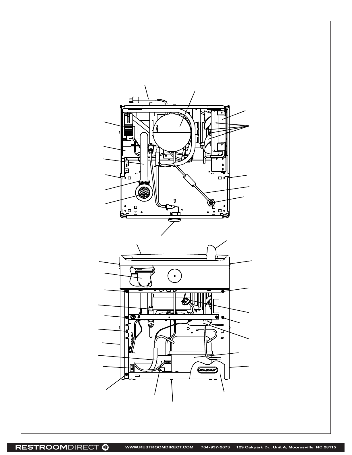
Note: Danger! Electrical shock hazard. Disconnect power before servicing unit.
Uses HFC-134A refrigerant
17
29
39
21, 15
10
20
38
5
7
7
16
1
4
25
See Fig. 4
See Fig. 3
42
24, 30
41
6
8
33
40
55
42
6
6
3
6
19
11
32
6
9
37
2
Fig. 1
Page 298966C (Rev. D - 12/17)
Page 3
VRC8FR*1C VRCFRD_B
WWW.RESTROOMDIRECT.COM 704•937•2673 129 Oakpark Dr., Unit A, Mooresville, NC 28115
1 1/2"
38mm
FINISHED FLOOR
18 5/8"
474mm
HANGER BRACKET
C
6 1/4"
159mm
8"
203mm
12 5/16"
313mm
*
27"
686mm
2 5/8"
67mm
31 7/8"
809mm
*
*ADA REQUIREMENT
RIM HEIGHT
32 15/16"
837mm
ORIFICE HEIGHT
2 9/16"
7 1/4"
E
4 9/16"
116mm
5 3/4"
146mm
1 3/8"
35mm
L
C
1 3/8"
35mm
5 3/4"
146mm
B
E
185mm
11/16"
18mm
D
HOLES (5 PL)
5/16"
8mm
O
65mm
13 7/8"
352mm
4 1/2"
2 1/2"
64mm
3 1/2"
A
21 3/8"
542mm
25"
635mm
114mm
89mm
10"
254mm
5"
127mm
*REDUCE HEIGHT BY 3” FOR INSTALLATION OF CHILDREN’S ADA COOLER
F
18 3/8"
466mm
30 15/16"
787mm
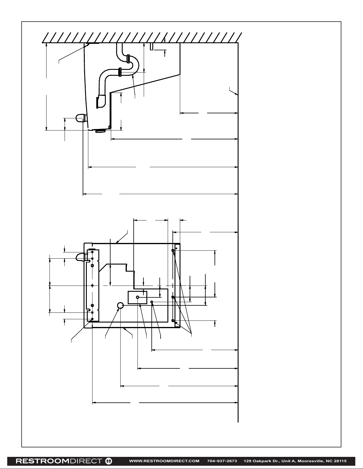
Fig. 2
Page 3 98966C (Rev. D - 12/17)
LEGEND
A = RECOMMENDED WATER SUPPLY LOCATION 3/8 O.D. UNPLATED COPPER TUBE CONNECT STUB WITH SHUT OFF (BY OTHERS) 3 IN. (76mm) MAXIMUM OUT FROM WALL
B = RECOMMENDED LOCATION FOR WASTE OUTLET 1-1/2” O.D. DRAIN STUB 2 IN. OUT FROM WALL
C = 1-1/2” TRAP NOT FURNISHED
D = ELECTRICAL SUPPLY (3) WIRE RECESSED BOX
E = INSURE PROPER VENTILATION BY MAINTAINING 6” (152 mm) (MIN.) CLEARANCE FROM CABINET LOUVERS TO WALL.
F = 7/16 BOLT HOLES FOR FASTENING UNIT TO WALL
Page 4
BASIN
WWW.RESTROOMDIRECT.COM 704•937•2673 129 Oakpark Dr., Unit A, Mooresville, NC 28115
Vandal-Resistant Bubbler
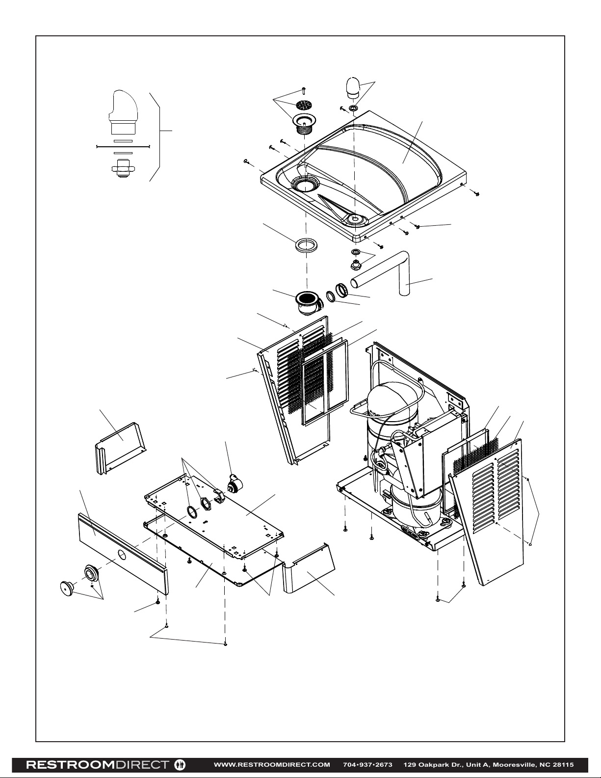
Fig. 3
VRC8FR*1C VRCFRD_B
1
4
25
1
36
35
27
42
14
33
42
30
24
26
15
18
21
1
31
39
42 (8)
31
18
32
27
43
42
28
43 (4)
34
42 (6)
Fig. 4
Page 498966C (Rev. D - 12/17)
42
Page 5
VRC8FR*1C VRCFRD_B
WWW.RESTROOMDIRECT.COM 704•937•2673 129 Oakpark Dr., Unit A, Mooresville, NC 28115
6
12
Fig. 5
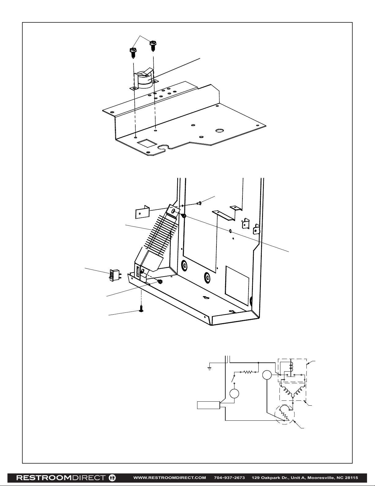
Thermostat Installation Detail
Fig. 6
Heater Strip Detail
17
55
22
42
WARNING!
This unit is frost resistant down to 0° F with no wind. Prevailing winds can reduce the ability of the heater element
to prevent light freezing. If the ambient air temperature will
drop below 0
by blowing out all water lines, evaporator (item 20), and the
drain trap. A heater strip is used to heat the unit and will
begin to cycle at 40
will ensure the heater is working and the unit is resistant to
light freezing.
ALSO, MAKE SURE THERE ARE NO PLASTIC OR FLAMMABLE COMPONENTS DIRECTLY ABOVE THE HEATER
STRIP.
°
F, the cooler needs to be drained of all water
°
+/- 5° F. A check at this temperature
GND
COLD CONTROL
(WATER)
23
BLK
WHT
HEATER
SWITCH
HEATER
HEATER
THERMOSTAT
FAN
1
0
12 13
M S
2
3
22
C
1
11
1
4
RELAY
COMPRESSOR
OVERLOAD
Wiring Diagram
Page 5 98966C (Rev. D - 12/17)
Page 6
115V PARTS LIST
WWW.RESTROOMDIRECT.COM 704•937•2673 129 Oakpark Dr., Unit A, Mooresville, NC 28115
ITEM
PART NO.
DESCRIPTION
NO.
1
2
3
4
5
6
7
8
9
10
11
12
13
14
15
16
17
18
19
20
21
22
23
24
25
26
27
28
29
30
31
32
33
34
35
36
37
38
39
40
41
42
43
NS
*REPLACE WITH SAME COMPRESSOR USED
IN ORIGINAL ASSEMBLY.
NOTE: All correspondence pertaining to any of the above
water coolers or orders for repair parts MUST include Model
No. and Serial No. of cooler, name and part number of replac
ement part.
97446C
98777C
1000001602
600985551640
98775C
70002C
75524C
98773C
0000000238
35870C
36322C
35909C
35907C
98530C
75589C
56092C
35906C
28617C
66703C
98724C
75588C
75506C
70432C
56121C
28963C
22897C
1000001906
55931C
27124C
100147140560
28596C
See Color Table
See Color Table
See Color Table
See Color Table
See Color Table
See Color Table
98776C
45930C
98778C
55996C
0000001190
70864C
28551C
NS = NOT SHOWN
Kit - Compr Mtg. Hardware/Studs/Clips/Grommets
KIt - Push Button/Sleeve/Spacer/Screw/Nuts
VR Bubbler Assy.
Kit - Elbow 5/16” x 1/4” (3 Pack)
Kit - Drain Plug/Strainer/Adapter/Screw
Kit - Fan Mtr/Blade/Shroud/Nut/Screws
Screw - #10 x 1/2” Lg. HHSM
Clip (Front & Rear Panels)
Kit - Cold Control/Screws
Kit - Elect/Relay/Overload/Cover
Power Cord
Compressor Serv. Pak EMI 70
FR Thermostat Assy.
Switch - Rocker
Kit - Regulator/Holder/Nut
Gasket
Tubing - Poly (Cut To length)
Heater Strip
Screen - VR
Evaporator Replacement Assembly
Strainer (See “General Instructions”)
Kit - #10 Pinned Torx Screws/T-25 Bit
Drier
Nut - 1-1/4” Slip Joint
Screw - #10 x .75 HHSM
Screw - 8-32 x .38 THTC
Elbow - Drain
Basin - Stainless Steel
Panel - Bottom Dispenser
Cover - Dispenser Bottom
Cover - Cold Control
Gasket - Drain
Panel - Screen
Panel - RH Rear
Panel - LH Rear
Panel - RH Dispenser Side
Panel - LH Dispenser Side
Panel - Dispenser Front
Panel - Front Lower
Kit - Condenser/Drier
Tube - Drain
Kit - Heat Exchanger/Drier
Screw - #8 x .62 Torx/Slot
Hanger Bracket
VRC8FR*1C VRCFRD_B
ALL SERVICE TO BE PERFORMED BY AN
AUTHORIZED SERVICE PERSON
1) Remove hanger bracket fastened to back of cooler by removing one (1) screw.
2) Mount the hanger bracket and trap as shown in Figure 2.
NOTE: Hanger Bracket MUST be supported securely. Add xture support carrier if wall will not
provide adequate support.
IMPORTANT:
• 6 1/4 in. (159mm) dimension from wall to centerline of trap must be maintained for proper t.
• Anchor hanger securely to wall using all ve (5) 1/4 in. dia. mounting holes.
3) Install straight valve for 3/8” O.D. tube.
4) Hang the cooler on the hanger bracket. Be certain the hanger bracket is engaged properly in
the slots on the cooler back as shown in Figure 2.
5) Loosen the two (2) screws holding the lower front panel at the bottom of cooler base and two
(2) screws at the top (Use torx bits sold separately). Remove the front panel and set aside.
6) Connect water inlet line--See Note 4 of General Instructions.
7) Remove the slip nut and gasket from the trap and install them on the cooler waste line making
sure that the end of the waste line ts into the trap.
Assemble the slip nut and gasket to the trap and tighten securely.
8) Stream height is factory set at 45-50 PSI. If supply pressure varies greatly from this, adjust
screw using the access hole in the pushbutton (insert screwdriver). CW adjustment will raise
stream and CCW adjustment will lower stream. For best adjustment, stream should hit basin
approximately 6-1/2” (165mm) from bubbler.
HANGER BRACKETS & TRAP INSTALLATION
IMPORTANT
INSTALLATION OF COOLER
START UP
Also See General Instructions
PRINTED IN U.S.A.
IMPRESO EN LOS E.E.U.U.
IMPRIMÉ AUX É.-U.
COLOR TABLE
PANEL COLOR
Stainless Steel
Item No. 32
Part No.
28525C 28519C
FOR PARTS, CONTACT YOUR LOCAL DISTRIBUTOR OR CALL 1.800.834.4816
REPAIR SERVICE INFORMATION TOLL FREE NUMBER 1.800.260.6640
Item No. 33
Part No.
28528C 28522C 22955C
Item No. 34
Part No.
Item No. 35
Part No.
Item No. 36
Part No.
28516C
Item No. 37
Part No.
ELKAY MANUFACTURING COMPANY • 2222 CAMDEN COURT • OAK BROOK, IL 60523 • 630.574.8484
Page 698966C (Rev. D - 12/17)
 Loading...