

Page 1
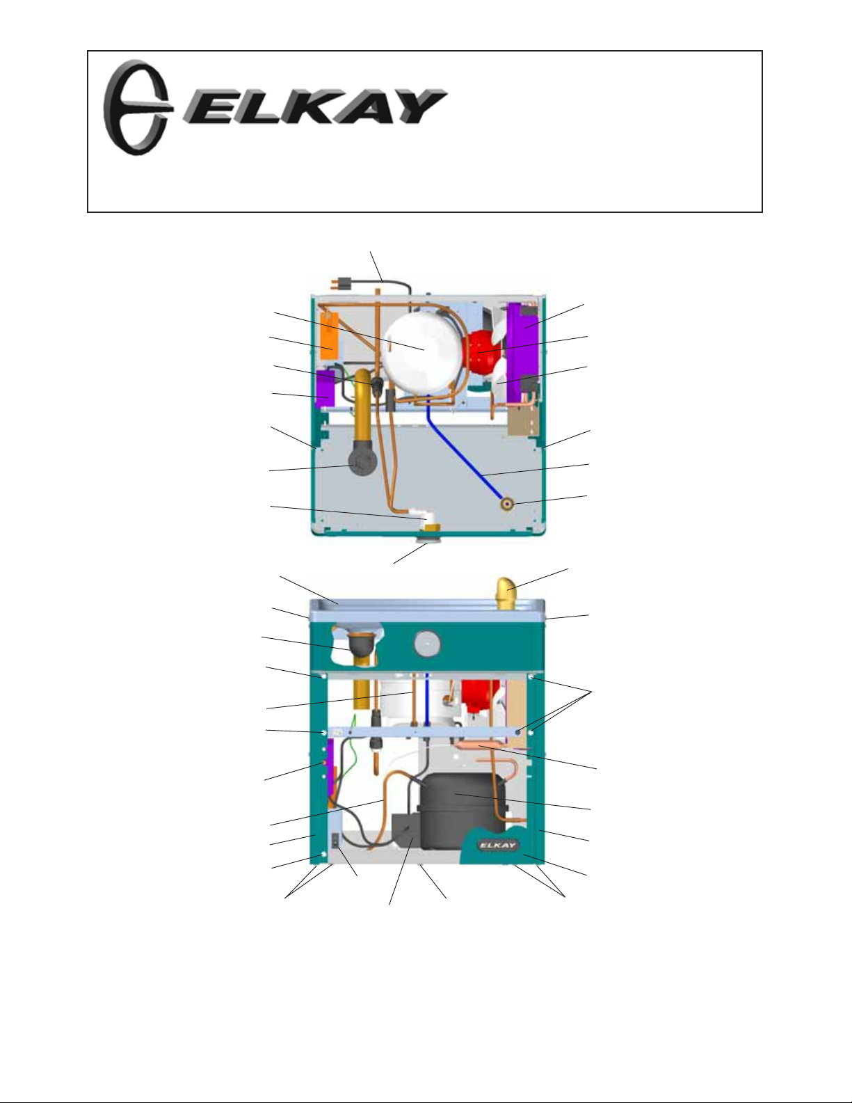
VRC8FR*1A VRCFRD*A
INSTALLATION, CARE & USE MANUAL
VRC Series Barrier-Free Water Coolers
TM
Uses HFC-134A refrigerant
10
20
54
43
51
42
23, 30
14, 17, 18
25
See Fig. 4
38, 39
7, 22, 41
6
42
16
1, 4
See Fig. 3
45
50
21
24
21
8
49
33
21
55
45
2, 3, 5
9, 12, 13
NOTE: Non-refrigerated units do not include all electrical and refrigeration
components shown above.
Other components and rough-in are the same as shown.
45
21
19
11
32
37
45
Page 1
98218C (REV. A - 3/06)
Page 2
VRC8FR*1A VRCFRD*A
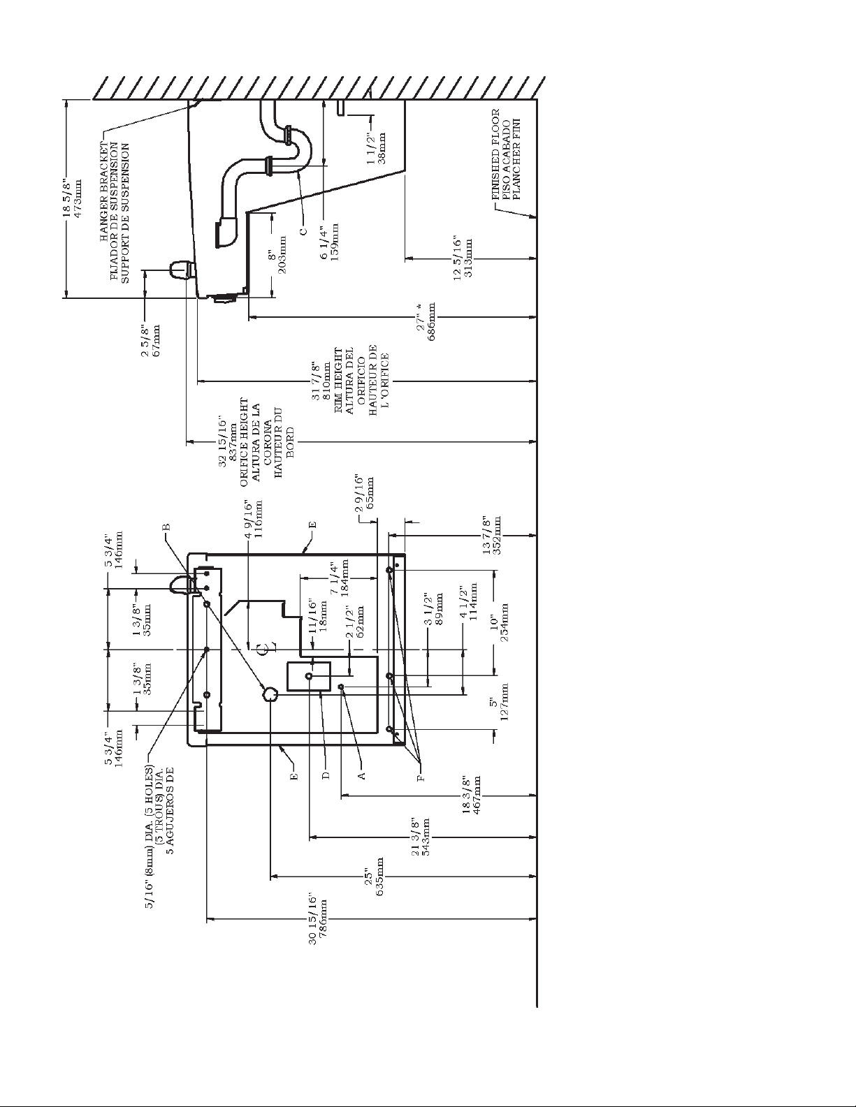
ADA REQUIREMENT
*
98218C (REV. A - 3/06)
Fig. 2
Page 2
REDUCE HEIGHT BY 3” FOR INSTALLATION OF CHILDRENS ADA COOLER
COPPER TUBE.
LEGEND/LEYENDA/LÉGENDE
A = RECOMMENDED WATER SUPPLY LOCATION. SHUT OFF VALVE (NOT FURNISHED) TO ACCEPT 3/8” O.D. UNPLATED
B = RECOMMENDED LOCATION FOR WASTE OUTLET 1-1/4” O.D. DRAIN
C = 1-1/4 TRAP NOT FURNISHED**
D = ELECTRICAL SUPPLY (3) WIRE RECESSED BOX
E = INSURE PROPER VENTILATION BY MAINTAINING 6" (152 mm) (MIN.) CLEARANCE FROM CABINET LOUVERS TO WALL.
F = 7/16 BOLT HOLES FOR FASTENING UNIT TO WALL
Page 3
VRC8FR*1A VRCFRD*A
ALL SERVICE TO BE PERFORMED BY
IMPORTANT
AN AUTHORIZED SERVICE PERSON
HANGER BRACKETS & TRAP
INSTALLATION
1) Remove hanger bracket fastened to back of cooler by removing one (1)
screw.
2 ) Mount the hanger bracket and trap as shown in Figure 2.
NOTE: Hanger Bracket MUST be supported securely. Add fixture support
carrier if wall will not provide adequate support.
IMPORTANT:
y 6 1/4 in. (159mm) dimension from wall to centerline of trap must be
maintained for proper fit.
y Anchor hanger securely to wall using all five (5) 1/4 in. dia. mounting
holes.
3 ) Install straight valve for 3/8" O.D. tube.
INSTALLATION OF COOLER
4) Hang the cooler on the hanger bracket. Be certain the hanger bracket is
engaged properly in the slots on the cooler back as shown in Figure 2.
5 ) Loosen the two (2) screws holding the lower front panel at the bottom of
cooler base and two (2) screws at the top (Use torx bits sold separately).
Remove the front panel and set aside.
6 ) Connect water inlet line--See Note 4 of General Instructions.
7 ) Remove the slip nut and gasket from the trap and install them on the cooler
waste line making sure that the end of the waste line fits into the trap.
Assemble the slip nut and gasket to the trap and tighten securely. Recommend fastening cooler to wall using 7/16 bolt holes. (see fig.2, "F")
START UP
8) Stream height is factory set at 45-50 PSI. If supply pressure varies
greatly from this, adjust screw using the access hole in the pushbutton
(insert screwdriver). CW adjustment will raise stream and CCW adjustment will lower stream. For best adjustment, stream should hit basin
approximately 6-1/2” (165mm) from bubbler.
Also See General Instructions
COLOR TABLE
PANEL COLOR
Stainless Steel
Item No. 32
Part No.
28525C 28519C
Item No. 33
Part No.
28528C 28522C 22955C
Item No. 34
Part No.
Item No. 35
Part No.
15
Basin
Estanque
1
Bassin
4
Fig. 3
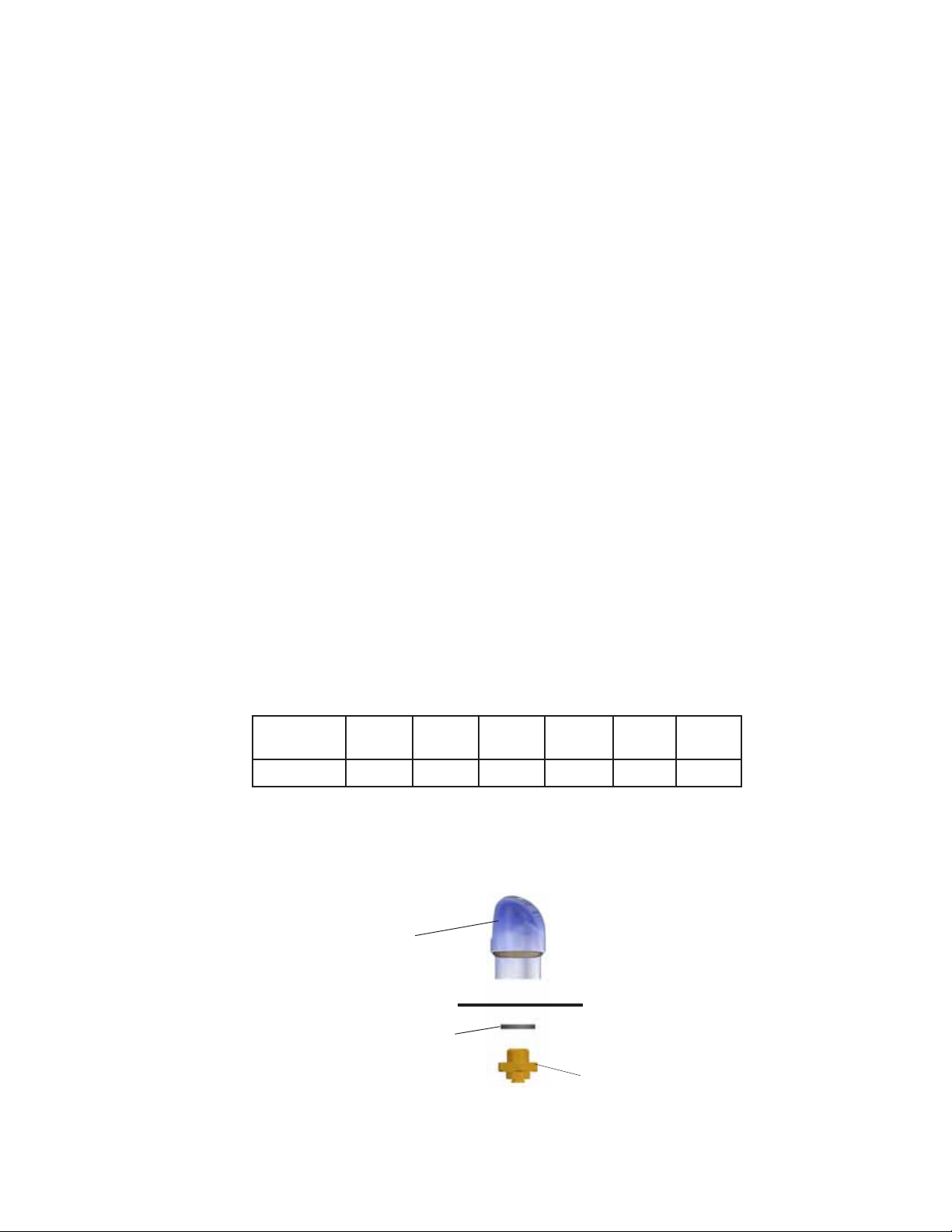
VANDAL RESISTANT BUBBLER DETAIL
DETALLE DEL GRIFO RESISTENTE AL VANDALISMO
DESCRIPTION DU BARBOTEUR RESISTANT AU VANDALISME
Item No. 36
Part No.
28516C
Item No. 37
Part No.
Page 3
98218C (REV. A - 3/06)
Page 4
VRC8FR*1A VRCFRD*A
23
30
15
25
45 (8)
28
35
48
40
44
46
33
46
50
1
4
53
31
31
53
46
14,17,18
26
27
29
Fig. 4
98218C (REV. A - 3/06)
36
46
52
46
34
32
47 (4)
45 (6)
46
Page 4
Page 5
56
VRC8FR*1A VRCFRD*A
Fig. 5
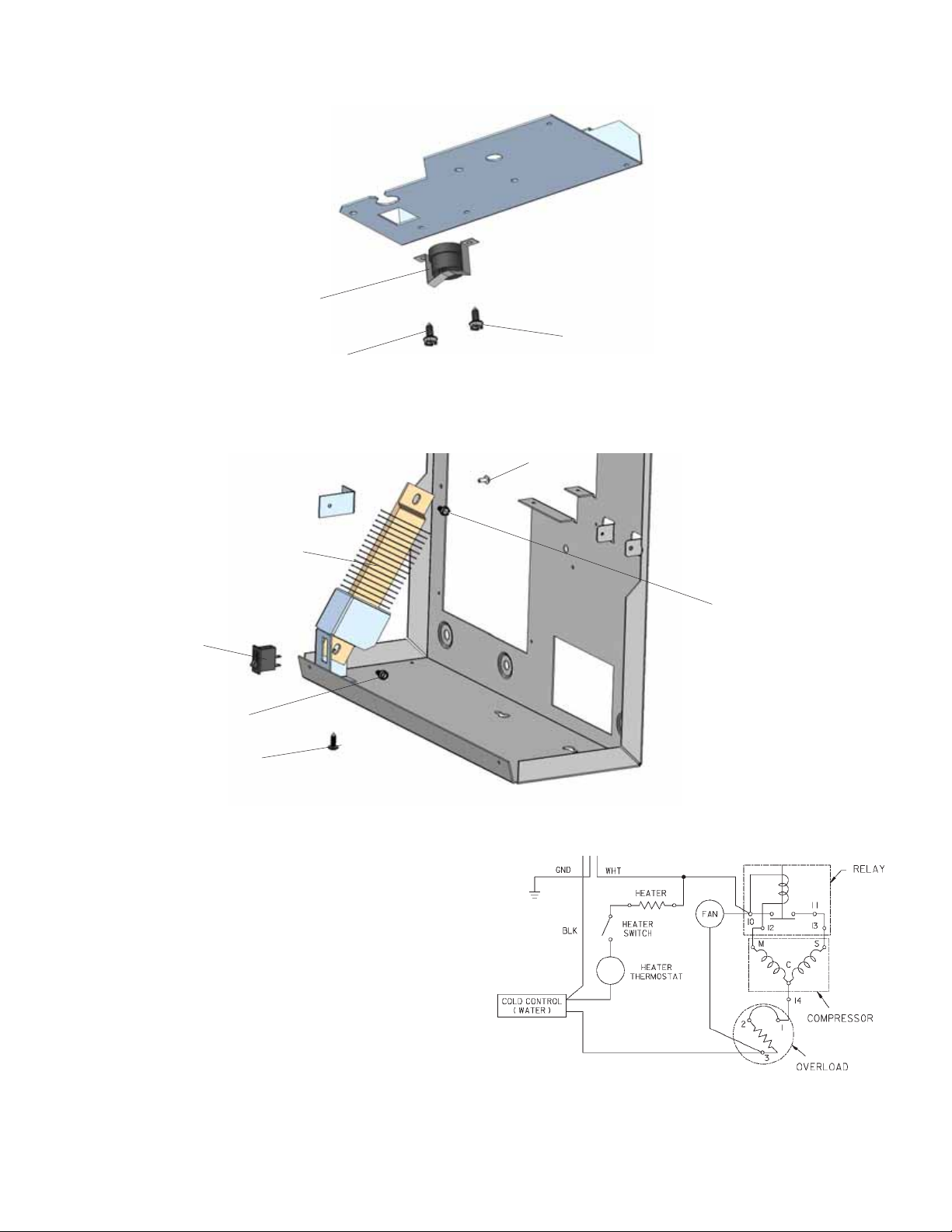
Thermostat Installation Detail
21
21
57
Fig. 6
Heater Strip Detail
54
55
58
45
WARNING!
This unit is frost resistant down to 0° F with no wind.
Prevailing winds can reduce the ability of the heater
element to prevent light freezing. If the ambient air
temperature will drop below 0
be drained of all water by blowing out all water lines,
evaporator (item 20), and the drain trap. A heater
strip is used to heat the unit and will begin to cycle
°
at 40
+/- 5° F. A check at this temperature will
ensure the heater is working and the unit is resistant to light freezing.
ALSO, MAKE SURE THERE ARE NO PLASTIC OR
FLAMMABLE COMPONENTS DIRECTLY ABOVE
THE HEATER STRIP.
°
F, the cooler needs to
58
Wiring Diagram
Page 5
98218C (REV. A - 3/06)
Page 6
115V PARTS LIST
ITEM NO.
1
2
3
4
5
6
7
8
9
10
11
*
12
13
14
15
16
17
18
19
20
21
22
23
24
25
26
27
28
29
30
31
32
33
34
35
36
37
38
39
40
41
42
43
44
45
46
47
48
49
50
51
52
53
54
55
56
57
58
Sold Separate
Sold Separate
NS
*REPLACE WITH SAME COMPRESSOR USED
IN ORIGINAL ASSEMBLY.
NOTE: All correspondence pertaining to any of the
above water coolers or orders for repair parts MUST
include Model No. and Serial No. of cooler, name and
part number of replacement part.
PART NO.
100322740560
100806740570
101516143550
15009C
19037000
30664C
31490C
31513C
35768C
35870C
36094C
36158C
35959C
50986C
45866C
56092C
15005C
61313C
66703C
66534C
70002C
70009C
45768C
66723C
28593C
22897C
45662C
45737C
75672C
56163C
28596C
See Color Table
See Color Table
See Color Table
See Color Table
See Color Table
See Color Table
66743C
56237C
40045C
70018C
75524C
55996C
45736C
75570C
75661C
70864C
56033C
66576C
45849C
27124C
55931C
28617C
35906C
35907C
35909C
70432C
75506C
75520C
75523C
28551C
DESCRIPTION
Gasket - Bubbler
Grommet - Compressor Mtg.
Stud - Compressor Mtg.
Nipple - Bubbler
Clip - Compressor Mtg.
Fan Blade
Fan Motor
Cold Control
Cover - Relay
Power Cord
Compressor Serv. Pak EMI 70
Screw - #10 x 1/2” Lg. HHSM
Strainer (See “General Instructions”)
Screw - #10 x .50 Pinned Torx
Screw - #8 x .50 Pinned Torx
Overload
Relay
Holder - Regulator
Bubbler Assy.
Tubing - Poly (Cut To length)
Retaining Nut
Regulator
Drier
Evaporator Assembly
Screw - Fan Motor
Drain Plug 1-1/2
Tube - Evap to Base
Basin - Stainless Steel
Panel - Bottom Dispenser
Button - Push
Sleeve - Push Button
Cap Screw
Gasket - Drain
Panel - Screen
Panel - RH Rear
Panel - LH Rear
Panel - RH Dispenser Side
Panel - LH Dispenser Side
Panel - Dispenser Front
Panel - Front Lower
Condenser
Shroud Fan
Hex Nut
Hex Nut - Fan Blade
Clip (Front & Rear Panels)
Half Nut - Regulator
Screw - #8 x .62 Torx/Slot
Washer
Heat Exchanger
Assy. Drain/Tailpipe
Cover - Cold Control
Cover - Dispenser Bottom
Screen - VR
Heater Strip
Switch - Rocker
FR Thermostat Assy.
Screw - 8-32 x .38 THTC
Screw - #10 x .75 HHSM
Torx Tool - T25
Torx Tool - T20
Hanger Bracket
VRC8FR*1A VRCFRD*A
PRINTED IN U.S.A.
IMPRESO EN LOS E.E.U.U.
IMPRIMÉ AUX É.-U.
98218C (REV. A - 3/06)
www.DrinkingFountainDoctor.com 800-518-5388
Page 6
 Loading...