

Elkay pushbutton, touchsensor, 350A-1, 350A-2, 360A-1 Fitting And Operating Instructions
...Page 1
pushbutton/touchsensor
master unit - two wire
Product: 350A-1, 350A-2, 360A-1, 360A-2, 750A-1, 760A-1,
550A-3, 550A-4, 560A-3, 560A-4 Two wire
Rating at 240V ac
• Incandescent 16A • Compact Fluorescent 16A
• Resistive 16A • Fluorescent 16A • Time Delay 2min - 2h
The pushbutton/touch timer are part of the Elkay family of
switches, timers and detectors which save energy and increase
convenience in and around your home, garden or premises.
energysense
ene
rgystyle
energyo
utdoor
pushbutton & touchsensor fitting and operating instructions
IMPORTANT NOTICE
All wiring should be carried out by a competent person or a qualified electrician and should be fitted to IEE 17th Edition Wiring regulations BS7671:2008.
Call +44 (0) 1675 468222 or click www.elkay.co.uk
pushbutton & touchsensor
Pushbutton
Touch
Usage
The push button/touch timer are general purpose time controls.
Applications for suitable use include lighting and some heating
and ventilation controls. The timers can be used independently or
as a master unit when using slave trigger switches. One master
product only for each circuit being switched with additional slave
units at other positions in the circuit.
WHEN USED WITH SOME LOW WATTAGE LIGHTING,
HEATING AND VENTILATION CIRCUITS PLEASE ENSURE A
CAPACITOR OF 2 MICROFARADS (MINIMUM) IS FITTED.
SUPPLIES OF SUITABLE ELKAY CAPACITORS CAN BE FOUND
AT YOUR STOCKIST (REF PFCC-1)
IMPORTANT Please note that it is essential that the live in and
live out are identified prior to commencing the installation
and steps 1 – 3 are followed precisely. No neutral is required on
this product (See diagram 1). Do not install the switch timer
with the mains power on as this can damage the product.
NOT SUITABLE FOR USE WITH CONTACTORS. DO NOT MEGGER
TEST OR INSULATION RESISTANCE TEST THIS PRODUCT.
REMOVE BEFORE TESTING OR TEST CIRCUIT PRIOR TO FITTING.
Your Elkay unit is compatible with a single gang, 25mm deep
British Standard accessory plate. Please ensure that the
top and bottom lugs are removed from metal wall boxes
prior to fitting. For 16mm boxes Elkay provide a spacer plate
(product code220A-1) to take box depth to 25mm.
Slave fitting
When connecting with slaves use three core cable connecting the
live in, live out and trigger terminals as shown in Diagram 2. The
optional wire to the slaves only applies to the 350A and 550A
push button slave units and is ideal for retrofitting (See diagram 2).
Please note that the trigger terminal is the third terminal. This
product requires a 24 hour power supply. The battery inside the
unit recharges when the light source or appliance is switched
OFF. Where the supply may be interrupted or isolated regularly
we must recommend our products from the three wire range.
Installation Steps
DO NOT APPLY MAINS UNTIL INSTRUCTED!
Step 1 - Ensure that the mains power to the circuit is switched off.
Place the previously identified Live In into the terminal marked L In
and the switched Live Out into the L Out terminal.
Step 2 - Switch the battery (switch 4) – you will notice a red LED
light flashing on the front of the unit- which will be flashing
rapidly. Whilst this is in action please select the desired timings
by selecting the appropriate time settings shown in diagram 3.
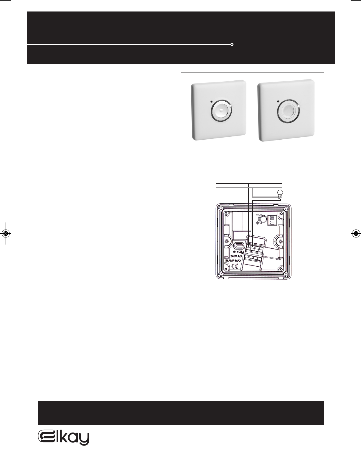
Diagram 1
Wiring diagram for a single sensor unit.
Lux level
adjustment
LIVE IN
NEUTRAL
LIVE OUT
Battery
4.
3.
2.
1.
DIL
switches
Page 2

IMPORTANT NOTICE
All wiring should be carried out by a competent person or a qualified electrician and should be fitted to IEE 17th Edition Wiring regulations BS7671:2008.
TECHNICAL HELPLINE
For further help or assistance or information on this or other products in the range please call the Elkay Technical team on 01675 468222.
Please call the Technical helpline before returning any products to your stockist. In the unlikely event that you have to return your product
please ensure you switch the battery off first.
Elkay Electrical, Coleshill, Birmingham, England.
Tel: +44 (0) 1675 468222 www.elkay.co.uk
For further wiring diagrams and more information on our products please visit our website on www. elkay.co.uk
energysense
ene
rgystyle
energyo
utdoor
pushbutton & touchsensor fitting and operating instructions
pushbutton & touchsensor
Step 3 - Attach the unit with the screws to the wall, then clip
on the front fascia plate. The red LED light will now change to a
single flashing light every 3 seconds approximately. You are now
ready to apply the mains power. The light or chosen appliance
will now start. Press and hold the button, the red flashing light
goes off and the blue locator ring will light up around the
push button/touch pad. Your light source or appliance will
now be switched off and ready for operation.
Operation
1. Press the pushbutton/touch pad and the red LED will light
once. Your light source or appliance will now be switched
on. Please note that the pushbutton has an audible click.
2. At any time during the working of the light source or
appliance, the push button/touch pad can be pressed to
reset the timing sequence to the originally set time,
e.g when the timing period is 30 minutes, if pressed 15 minutes
into the sequence, the timer will reset to 30 minutes.
3. To end the timing sequence prematurely, press and hold the
push button/touch pad until the red LED flashes
continuosly indicating the last minute countdown is in
operation. Your light source or appliance will now be
switched off, after one minute.
4. At one minute prior to the end of the timing sequence, the
red LED will begin to flash continuously for the last minute
of operation. The blue locator ring will then illuminate once
the light source or appliance has gone off.
Operation Notes
If the Elkay Timer does not receive power then the unit will put
the unit into sleep mode to conserve the battery. To reactivate
the unit press and hold for a period of 15 seconds approximately,
the red LED should start to flash, release button, the LED changes
to a flash every 3 seconds press and hold again until load switches
off. The unit will attempt to latch on to the mains power 25 times
automatically before going to sleep mode as mentioned above.
Outdoor Installation
Please note only products in the Elkay energy outdoor range are
suitable for use outdoors. Elkay energy outdoor can only be used
in conjunction with the surface mount box supplied. Take the
surface mount box and remove the knock out section. If required
and to ensure IP66 waterproof rating, please use a suitable M20
cable gland and use appropriate sealing washers. Mount the
surface mount box on a secure surface using the mounting pack
supplied. Place screw cover seals over the mounting screws. It is
essential that the correct IP66 rated connections are made to keep
the IP66 rating of the back box. Steel wire armored connections
without seals are not appropriate.
Turn off mains supply before proceeding with installation - Install
as per previous remote installation instructions - Mount unit
onto surface mount box using the fixing screws at all four corners
ensuring even connection with the seal - Place screw hole seals
over left and right screw cavities - Clip on front fascia plate Re-instate mains supply.
4.
3.
2.
1.
4.
3.
2.
1.
4.
3.
2.
1.
4.
3.
2.
1.
4.
3.
2.
1.
4.
3.
2.
1.
4.
3.
2.
1.
4.
3.
2.
1.
ON DIP
ON DIP
ON DIP
ON DIP
ON DIP
ON DIP
ON DIP
ON DIP
2 mins 5 mins 10 mins 20 mins 40 mins 60 mins 90 mins 120 mins
Diagram 3 - time settings
Please note that the black bar denotes the position of the dip switch.
*Optional wire for blue indicator
ring on push button slaves only
LIVE IN
NEUTRAL
LIVE OUT
DIL
switches
1.
2.
3.
4.
Battery
Lux level
adjustment
Diagram 2
Wiring diagram for a sensor unit with slave.
 Loading...