

Elkay SJ2 Installation Manual
SJ2Q*1B
Halsey Taylor Owners Manual
SJ2
Refrigeration Package
Note: Danger! Electric shock hazard. Disconnect power before servicing unit.
USES HFC-134A REFRIGERANT
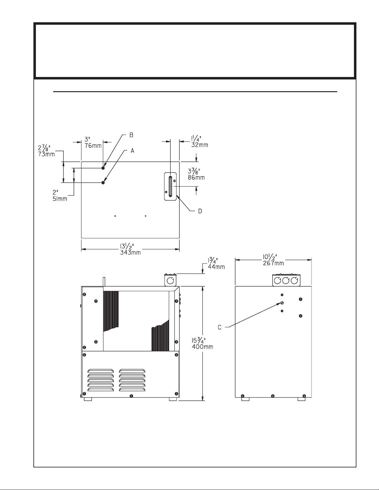
NOTE: It is important to insure proper ventilation. Allow a
minimum clearance of 6 inches (152 mm) in front and 3 inches
(76mm) in the rear of the unit. If unit is to be installed in an
enclosure, allow the following clearances around unit - 1 inch
(25mm) each side, 3 inches (76mm) in the rear, 3 inches (76mm)
inches above wall.
This chiller has been designed for use with potable water ONLY.
LEGEND
A= 1/4" (6mm) O.D. TUBE WATER OUT
B = 1/4" (6mm) O.D. TUBE WATER INLET
C = TEMPERATURE ADJUSTMENT
D = ELECTRICAL
98708C (Rev. C - 05/16)
SJ2Q*1B
ITEM
NO.
*9
10
11
12
13
14
15
16
17
18
NS
NS
*INCLUDES RELAY & OVERLOAD. IF UNDER
WARRANTY, REPLACE WITH SAME COMPRESSOR
USED IN ORIGINAL ASSEMBLY.
NOTE: All correspondence pertaining to any of the
above water cooler or orders for repair MUST include
model number and serial number of cooler, name and
part number of replacement part.
1
2
3
4
5
6
7
8
PAR T
NO.
30040C
30039C
98773C
98788C
42677000
98181C
66201C
66266C
0000001194
98747C
98777C
98724C
50930C
23105C
27304C
23107C
23108C
23109C
56092C
1000001602
DESCRIPTION
Cover - Electrical Box
Box - Electrical
Kit - Cold Control/Screws
Kit - Fan Motor Assy/Blade
Fan - Bracket
Kit - Heat Exchanger/Drier
Drier
Condenser
Compressor Service Pak
Kit - Electrical (Relay/Cvr/O/L)
Kit - Compr Mtg Hdwe/Grommets/
Clips/Studs
Evaporator Replacement Assy
Bumper
Cabinet
Baseplate
Panel - Rear (Not Shown)
Panel - Front
Panel - Condenser Mounting
Poly Tubing (Cut to Length)
Kit - Elbow - 5/16" x 1/4" (3 Pack)
1. It is important to insure proper ventilation. For remote installation a minimum clearance of 6 inches
(152 mm) to the front must be maintained, 1 inch (25 mm) each side, 3 inches (76 mm) to the rear
above the unit.
2. When unit is installed in a kitchen cabinet, two air openings with a minimum of 40 square inches each
(minimum of 75% open area) must be provided in the cabinet. One opening should be in the overhang
of the toe space. The other opening near the top of the cabinet. The remote unit must be installed with
a minimum of 3 inch clearance between the unit and the walls of the cabinet. In addition a minimum 2
inch clearance must be provided between the toe space air opening and front of remote unit.
3. Water inlet is 1/4" (6 mm) O.D. tube. Contractor to supply connections as required.
4. Connecting lines to be of copper, thoroughly ushed to remove all foreign matter before being
connected to chiller. If ushing does not remove all particles, a water strainer should be installed in
supply line.
5. Connect cooler to building supply line with a shut-off valve and install a union connection between the
valve and chiller.
6. Electrical: Make sure power supply is identical in voltage, cycle, and phase to that specied on chiller
serial plate. Never wire compressor directly to the power supply.
1. Open supply line valve.
2. Purge air from all water lines by operating bubbler valve of fountain to which chiller is connected.
Steady stream assures all air removed.
3. Rotate fan to insure proper clearance and free fan action.
4. Connect to electrical power.
Temperature Control: Factory set at 50°F (+/- 5°) under normal conditions. For colder water, adjust screw on item
no. 3 CW.
Ventilation: Cabinet louvers and condenser ns should be periodically cleaned with brush, air hose or vacuum
cleaner. Excess dirt or poor ventilation can cause no cold water and compressor cycling on the compressor overload protector.
Lubrication: Motors are lifetime lubricated.
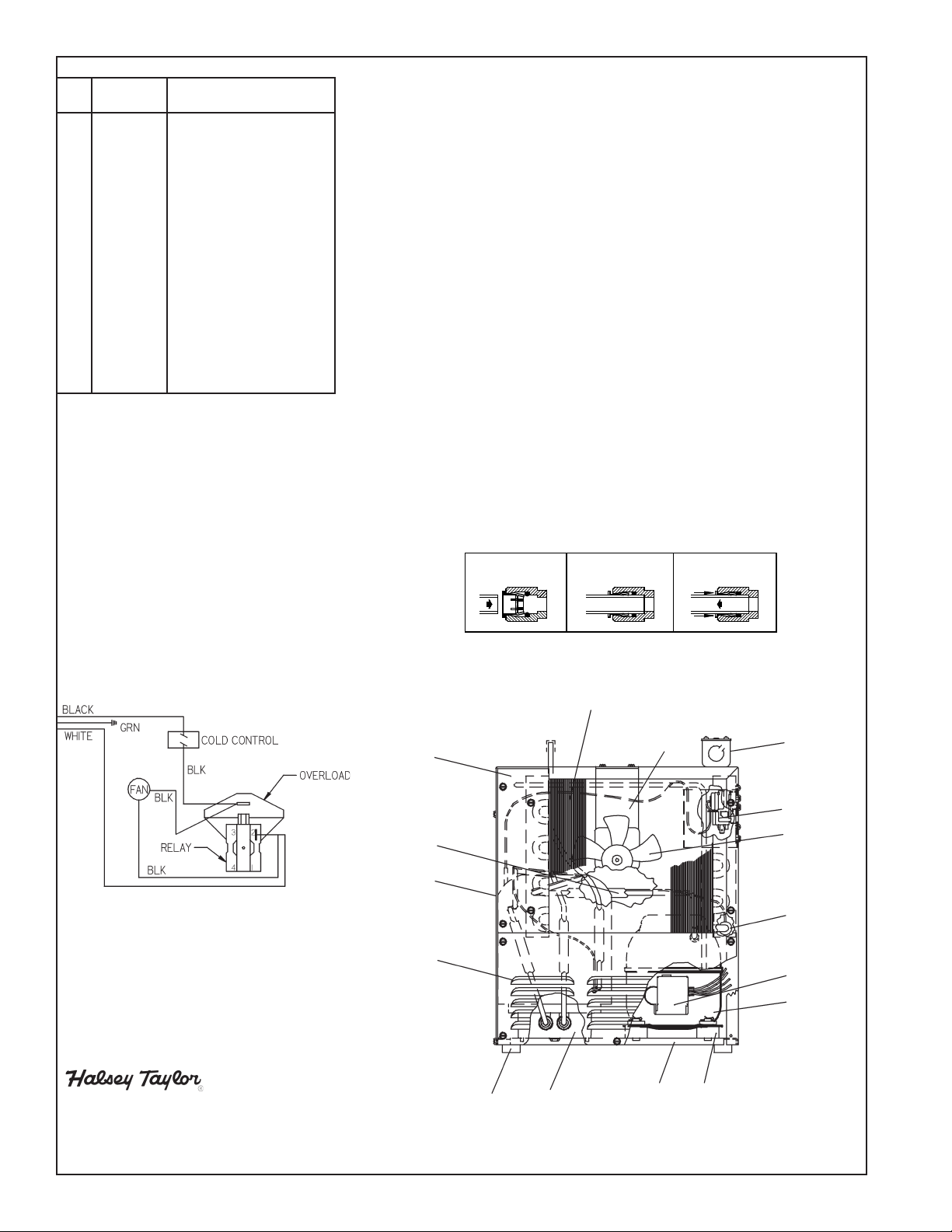
Chiller is provided with a lead-free plug which utilizes an o-ring water seal. To remove plug from chiller, relieve
water pressure, pull the collar towards the tting and pull the tting off the tube. To install plug, push tting straight
onto tubing until it reaches a positive stop, approximately 3/4 in. (19mm).
TROUBLE SHOOTING & MAINTENANCE
ACTUATION OF QUICK CONNECT WATER FITTINGS:
INSTALLATION
START-UP
115V
WIRING DIAGRAM
18
14
6
17
OPERATION OF QUICK CONNECT FITTINGS
OPERATION OF QUICK CONNECT FITTINGS
SIMPLY PUSH IN
SIMPLY PUSH IN
TUBE TO ATTACH
TUBE TO ATTACH
A B C
TUBE IS SECURED
TUBE IS SECURED
IN POSITION
IN POSITION
B CA
PUSH IN COLLET
PUSH IN COLLET
TO RELEASE TUBE
TO RELEASE TUBE
PUSHING TUBE IN BEFORE
PUSHING TUBE IN BEFORE
PULLING IT OUT HELPS TO
PULLING IT OUT HELPS TO
RELEASE TUBE
RELEASE TUBE
8
5
1, 2
3
4
7
10
9
2222 CAMDEN COURT
OAK BROOK, IL 60523
630.574.3500
PRINTED IN U.S.A.
98708C (Rev. C - 05/16)
13
FOR PARTS CONTACT YOUR LOCAL DISTRIBUTOR OR VISIT OUR WEBSITE WWW.HALSEYTAYLOR.COM
12
15 11
 Loading...