

Page 1
ERFP8C*B ERFPVR8C LNFE8C*B
Installation/Care/Use Manual
Soft Sides® Refrigerated Fountains with FLEXI-GUARD
ERFP8C
Installer
To assure you install this model easily and correctly, PLEASE READ
THESE SIMPLE INSTRUCTIONS BEFORE STARTING THE INSTALLATION. CHECK YOUR INSTALLATION FOR COMPLIANCE WITH
PLUMBING, ELECTRICAL AND OTHER APPLICABLE CODES. After
installation, leave these instructions inside the fountain for future reference.
®
IMPORTANT
ALL SERVICE TO BE PERFORMED BY AN AUTHORIZED SERVICE PERSON
IMPORTANT! INSTALLER PLEASE NOTE.
THE GROUNDING OF ELECTRICAL EQUIPMENT SUCH AS TELEPHONE, COMPUTERS, ETC. TO WATER LINES
IS A COMMON PROCEDURE. THIS GROUNDING MAY BE IN THE BUILDING OR MAY OCCUR AWAY FROM THE
BUILDING. THIS GROUNDING CAN CAUSE ELECTRICAL FEEDBACK INTO A FOUNTAIN, CREATING AN ELECTROLYSIS WHICH CAUSES A METALLIC TASTE OR AN INCREASE IN THE METAL CONTENT OF THE WATER.
THIS CONDITION IS AVOIDABLE BY USING THE PROPER MATERIALS AS INDICATED. ANY DRAIN FITTINGS
PROVIDED BY THE INSTALLER SHOULD BE MADE OF PLASTIC TO ELECTRICALLY ISOLATE THE FOUNTAIN
FROM THE BUILDING PLUMBING SYSTEM.
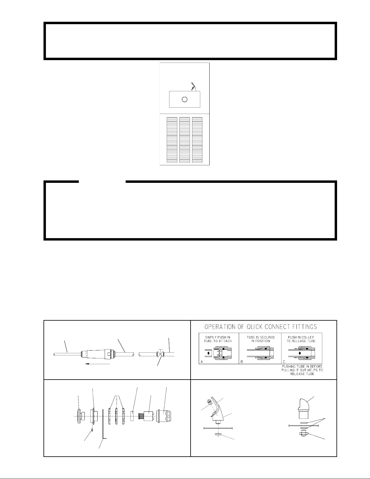
1/4" O.D. TUBE
WATER INLET
TO COOLER
FIG. 1
3/8" O.D. UNPLATED
COPPER TUBE CONNECT
COLD WATER SUPPLY
NOTE: WATER FLOW
DIRECTION
4
3
17
BUILDING WATER
INLET
SERVICE STOP
(NOT FURNISHED)
2
10
FIG. 2
5
6
NOTE: WHEN INSTALLING
REPLACEMENT BUBBLER
AND PEDESTAL, TIGHTEN
7
NUT (ITEM 9 OR 32) ONLY
TO HOLD PARTS SNUG IN
POSITION. DO NOT
8
OVER TIGHTEN.
34
33
FIG. 3
11
19
PAGE 1
FIG. 4
9
32
FIG. 5
97157C (Rev. L - 1/02)
Page 2
ERFP8C*B ERFPVR8C LNFE8C*B
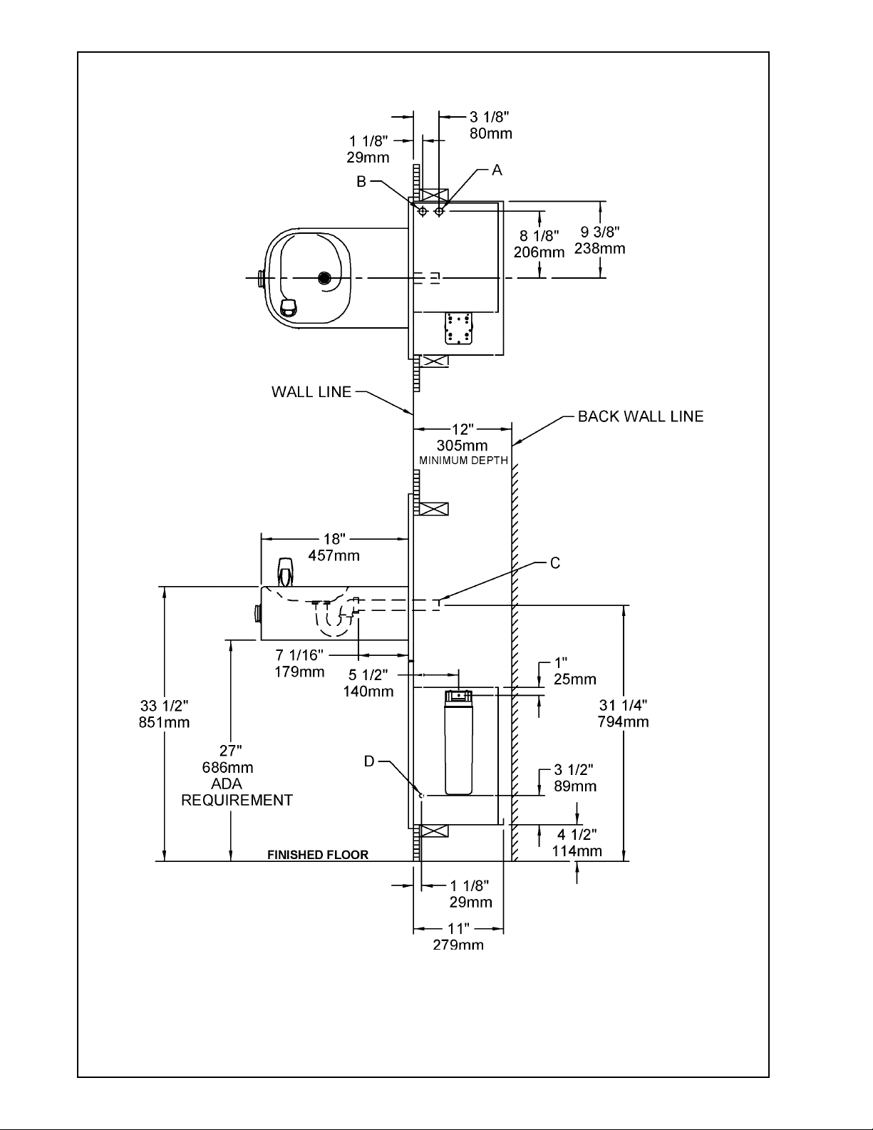
MODEL LNFE8C
LEGEND
A = 3/8" O.D. TUBE CONNECT (CHILLER WATER OUTLET)
B = 3/8" O.D. TUBE CONNECT (CHILLER WATER INLET) SHUT OFF VALVE BY OTHERS
C = 1-1/4" TRAP FURNISHED
D = ELECTRICAL INLET
97157C (Rev. L - 1/02)
FIG. 6
PAGE 2
Page 3
ERFP8C*B ERFPVR8C LNFE8C*B
INSTALLATION INSTRUCTIONS
1. Install remote chiller. Remove front panel of chiller. Remove and discard cardboard inner pack from between compressor and
side panel. Slide chiller onto the shelf and position it to the left within the guides on the shelf.
NOTE: Building construction must allow for adequate air flow on both sides, top, and back of chiller. See chiller instructions for
additional instructions.
2. Make water supply connections. Install a shut-off valve and union connection to building water supply (valve and union not
provided). Turn on the water supply and flush the line thoroughly.
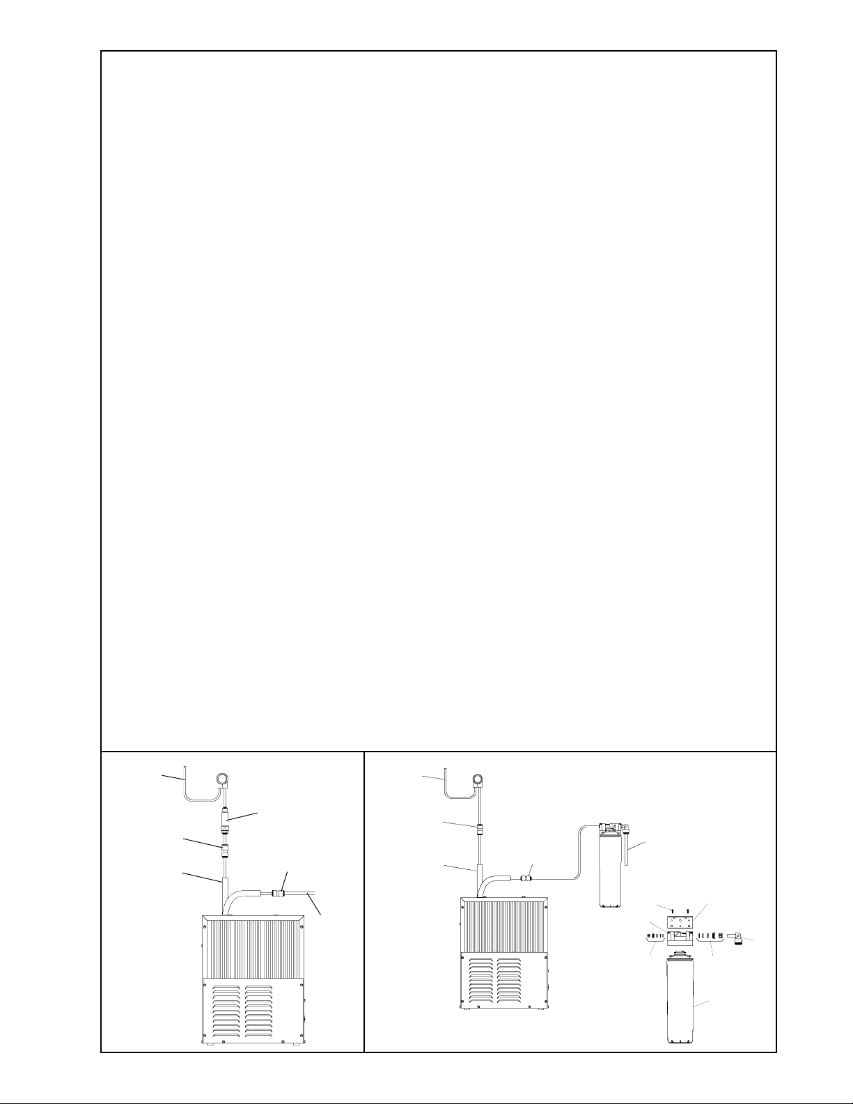
3. ERFP MODELS: Make connection between remote chiller and building supply line. Inlet port is marked on the chiller (1/4" O.D.
copper tube). Bend the copper tube (provided) at an appropriate length from chiller to opening in frame. Install a 1/4" x 3/8" union
(provided) on the marked chiller inlet port. Connect building supply line to union. (See Figures 7 or 12)
LNFE MODEL: Mount filter head assembly to side of chiller (See Figure 9). Make connection between filter and building supply
line (3/8" O.D. tube not provided). Inlet port is marked on the chiller (1/4" O.D. copper tube). Install a 1/4" x 1/4" union (provided).
Bend the copper tube (provided) at an appropriate length from the filter and connect to the union on the chiller. (See Figures 8 or 11).
4. Hang the upper panel on the mounting frame hanger. Align holes in the panel with the holes in the mounting frame. Be sure that
panel is engaged with hanger at top of frame before releasing it.
5. Install the fountain. Remove access cover plate on underside of fountains and save the screws. Mount the fountain to the
upper panel and the wall frame with (4) 5/16" x 3/4" (19mm) long bolts and nuts (provided). Tighten securely.
6. Remove elbow from end of p-trap and attach it to drain tube. Re-attach elbow to p-trap and cut waste tube to required length
using plumbing hardware and trap as a guide.
7. ERFP MODELS: Make connections between remote chiller outlet tube and fountain strainer. Outlet port is marked on the chiller
(3/8" O.D. copper tube). Install a 3/8" x 3/8" union (provided) on the marked chiller outlet port. Insert the 3/8" unplated copper
water line (provided) into the union and the inlet side of the strainer by pushing it in until it reachs a positive stop, approximately
3/4" (19mm). Connect 1/4" copper tubing coming from fountain to the strainer. Turn on water supply and check for leaks. DO NOT
SOLDER TUBES INSERTED INTO THE STRAINER AS DAMAGE TO THE O-RINGS MAY RESULT. (See Figures 7 or 12).
LNFE MODEL: Make connections between remote chiller and fountain. Outlet port is marked on the chiller (3/8" O.D. copper
tube). Install a 3/8" x 3/8" union (provided) on the marked chiller outlet port. Insert the 3/8" unplated copper water line (provided)
into the union. Install a 1/4" x 3/8" union (provided) on the 3/8" copper tube and connect to the 1/4" copper tubing coming from the
fountain. Turn on water supply and check for leaks. DO NOT SOLDER TUBES INSERTED INTO THE UNIONS AS DAMAGE TO
THE O-RINGS MAY RESULT. (See Figures 8 or 11).
8. These products are designed to operate on 20-105 PSIG supply line pressure. If inlet pressure is above 105 PSIG, a pressure
regulator must be installed in the supply line. Any damage caused by reason of connecting these products to supply line
pressures lower than 20 PSIG or higher than 105 PSIG is not covered by warranty.
9. Make electrical connections to the chiller. See chiller instructions.
10. Check stream height from bubbler. Stream height is factory set at 35 PSI. If supply pressure varies greatly from this, remove
items 3 & 4 and adjust the screw on regulator (Item 10). Clockwise adjustment will raise stream height and counter-clockwise
will lower stream height. For best adjustment stream should hit basin approximately 6 1/2" from the bubbler.
11. Mount lower panel. Loosen the (2) #10-24 x 5/8" (16mm) screws at frame bottom lip. Slide upper tongue of lower panel under
lower edge of already installed upper panel. Tighten previously loosened screws securely.
12. Replace bottom access panel to fountain basin using screws provided. Tighten securely.
TROUBLE SHOOTING AND MAINTENANCE
1. Orifice Assy: Mineral deposits on orifice can cause water flow to spurt or not regulate. Mineral deposits may be removed
from orifice with a small round file not over 1/8" diameter or a small diameter wire.
CAUTION: Do not file or cut orifice materials.
2. Stream Regulator: If orifice is free of material deposits, regulate flow according to instruction 10 stated above.
3. Actuation of Quick Connect Water Fittings: Cooler is provided with lead-free connectors which utilize an o-ring water
seal. To remove tubing from the fitting, relieve water pressure, push in on the gray collar while pulling on the tubing (See Fig. 2)
To insert tubing, push tube straight into the fitting until it reaches a positive stop, approximately 3/4".
TO
BUBBLER
CHILLER
OUTLET
ERFP8C
TUBE ROUTING
13
22
21
CHILLER
INLET
TO
BUBBLER
CHILLER
OUTLET
21
LNFE8C
TUBE ROUTING
26
WATER
INLET
27
24
29
23
30
25
28
FIG. 7
FIG. 8
PAGE 3
97157C (Rev. L - 1/02)
Page 4
1
2
3
4
5
6
7
8
9
10
11
12
13
14
15
16
17
18
19
20
21
22
23
24
25
26
27
28
29
30
31
32
33
34
35
36
NS
NS
PART NO.ITEM NO.
LK464
15005C
45662C
45663C
50986C
A54874
50934C
50168C
70012C
61313C
70022C
110711942550
55996C
55000612
27959C
55000665
26837C
40045C
70055C
27057C
26833C
70745C
70870C
22490C
51294C
51299C
70683C
70792C
70818C
70822C
70823C
70682C
15009C
100322740560
45392C
56092C
62095C
111577243890
111577343890
ERFP8C*B ERFPVR8C LNFE8C*B
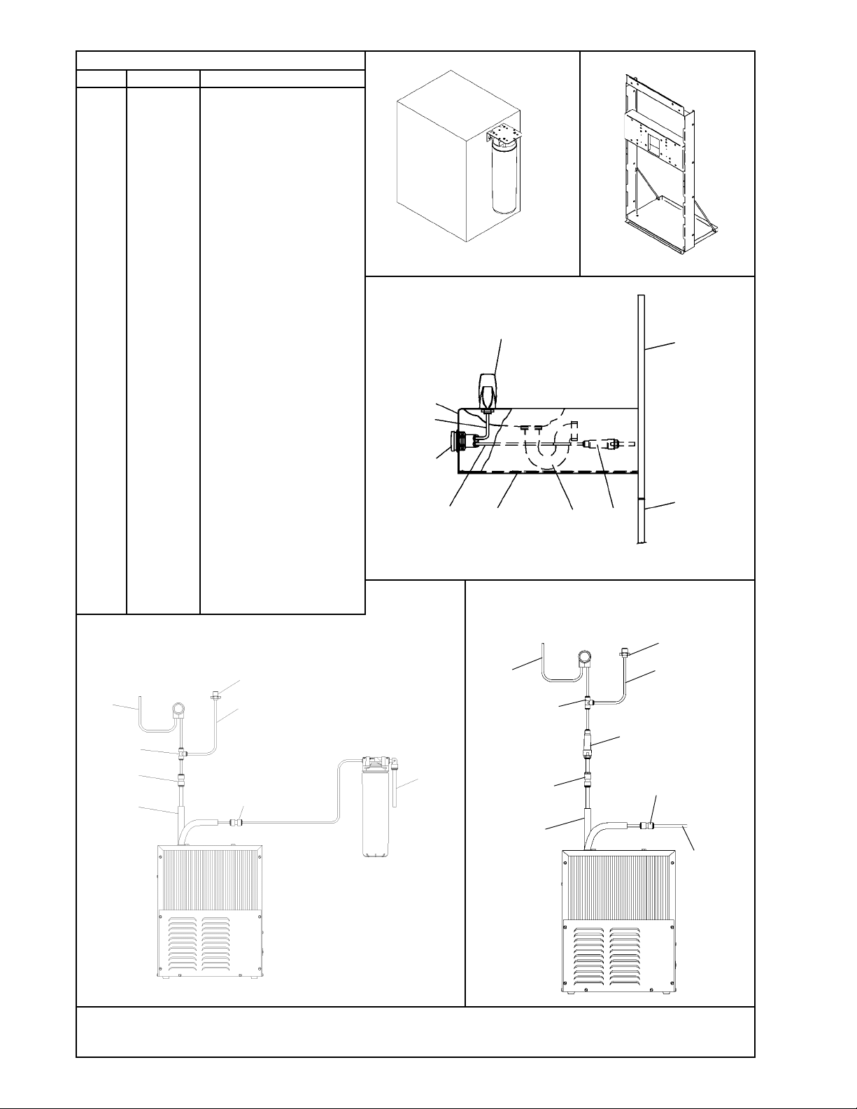
PARTS LIST
DESCRIPTION
Drain
Retaining Nut
Push Button
Push Button Sleeve
Regulator Holder
Orifice Assy
Housing Assy
Pedestal
Bubbler Locknut
Regulator
Setscrew - #6-32 X .31"
Screw - #8-32 X .38" TH
Strainer
Fountain Arm
Fountain Arm - (Glassfiller)
Bottom Cover Plate
Back Panel
Hex Nut
Speed Nut
Regulator Mounting Bracket
Lower Panel
Union - 3/8 X 1/4
Union - 3/8 X 3/8
Filter Mounting Bracket
Filter Head Assy
Filter Assy
Union - 1/4
Screw - #8-18 x .75" PH
Elbow - 3/8" (10mm)
Fitting - Superseal 1/4" (6mm)
Fitting - Superseal 3/8" (10mm)
Tee - 1/4
Nipple - Bubbler - VR Model
Gasket - VR Model
Bubbler - VR Model
Poly Tubing (Cut To Length)
Tube - Water In
Screw - Mach 5/16-18 x 3/4
Nut - Hex 5/16-18
FIG. 9
FIG. 10
14
35
SEE
FIG. 3
36
SEE FIG. 4 OR 5
12, 15, 18
ERFP8FC TUBE ROUTING
16
20
13
1
TO
BUBBLER
CHILLER
OUTLET
31
21
LNFE8FC TUBE ROUTING
32
TO GLASSFILLER
26
WATER
INLET
TO
BUBBLER
31
22
CHILLER
OUTLET
FIG. 12FIG. 11
www.DrinkingFountainDoctor.com 800-518-5388
32
TO GLASSFILLER
13
21
CHILLER
INLET
97157C (Rev. L - 1/02)
PAGE 4
 Loading...