

Page 1
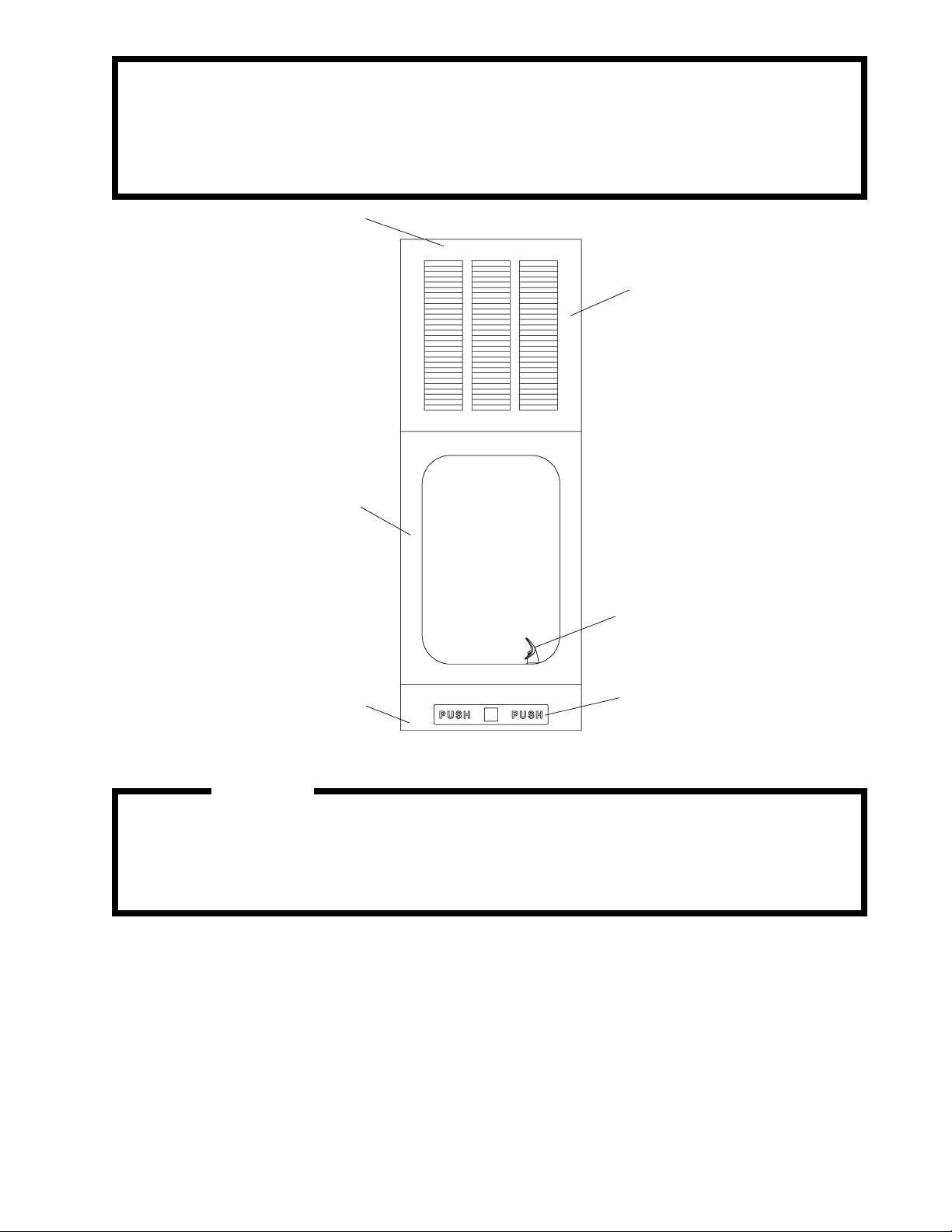
EHFRA7C*A EHFRA7FC*A
Installation/Care/Use Manual
Fully Recessed Refrigerated
Fountain with FLEXI-GUARD
35, 36
®
34
21
SEE FIG. 5
37
SEE FIG. 9
Installer
To assure you install this model easily and correctly, PLEASE READ THESE SIMPLE
INSTRUCTIONS BEFORE STARTING THE INSTALLATION. CHECK YOUR INSTALLATION FOR COMPLIANCE WITH PLUMBING, ELECTRICAL AND OTHER APPLICABLE
CODES. After installation, leave these instructions inside the fountain for future reference.
IMPORTANT
ALL SERVICE TO BE PERFORMED BY AN AUTHORIZED SERVICE PERSON
IMPORTANT! INSTALLER PLEASE NOTE.
THE GROUNDING OF ELECTRICAL EQUIPMENT SUCH AS TELEPHONE, COMPUTERS, ETC. TO
WATER LINES IS A COMMON PROCEDURE. THIS GROUNDING MAY BE IN THE BUILDING OR MAY
OCCUR AWAY FROM THE BUILDING. THIS GROUNDING CAN CAUSE ELECTRICAL FEEDBACK
INTO A FOUNTAIN, CREATING AN ELECTROLYSIS WHICH CAUSES A METALLIC TASTE OR AN
INCREASE IN THE METAL CONTENT OF THE WATER. THIS CONDITION IS AVOIDABLE BY USING
THE PROPER MATERIALS AS INDICATED. ANY DRAIN FITTINGS PROVIDED BY THE INSTALLER
SHOULD BE MADE OF PLASTIC TO ELECTRICALLY ISOLATE THE FOUNTAIN FROM THE BUILDING
PLUMBING SYSTEM.
97160C (Rev. C - 10/02)
Page 2
EHFRA7C*A EHFRA7FC*A
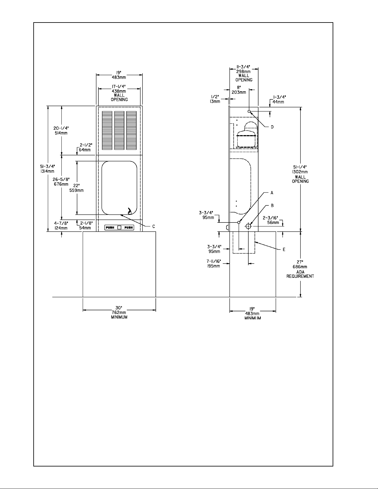
EHFRA7C ROUGH-IN
FINISHED
FLOOR LINE
FIG. 1
LEGEND:
A = RECOMMENDED WATER SUPPLY LOCATION 3/8" O.D. UNPLATED COPPER TUBE CONNECT
STUB 1-1/2" (38mm) OUT FROM WALL, SHUT OFF BY OTHERS (BOTH SIDES).
B = RECOMMENDED LOCATION FOR WASTE OUTLET 1-1/4" O.D. DRAIN (BOTH SIDES).
C = 1-1/4" TRAP NOT FURNISHED.
D = ELECTRICAL SUPPLY LOCATION (BOTH SIDES).
E = ACCESS TO TRAP MUST BE PROVIDED. IF REAR ACCESS IS NOT POSSIBLE, INSTALLATION
CAN BE MADE THROUGH OPTIONAL ACCESS PANEL AP-99.
97160C (Rev. C - 10/02)
PAGE 2
Page 3
EHFRA7C*A EHFRA7FC*A
INSTALLATION INSTRUCTIONS
1. Remove shipping brace from mounting box and discard.
2. Fasten mounting box into wall cutout using screws or bolts (provided by others) through holes or knockouts
provided on each side of the mounting box. (See Fig. 1)
3. Place refrigeration package into mounting box and connect water lines. (See Fig. 1)
4. Remove access panel (on bottom of mounting box) and install fountain body.
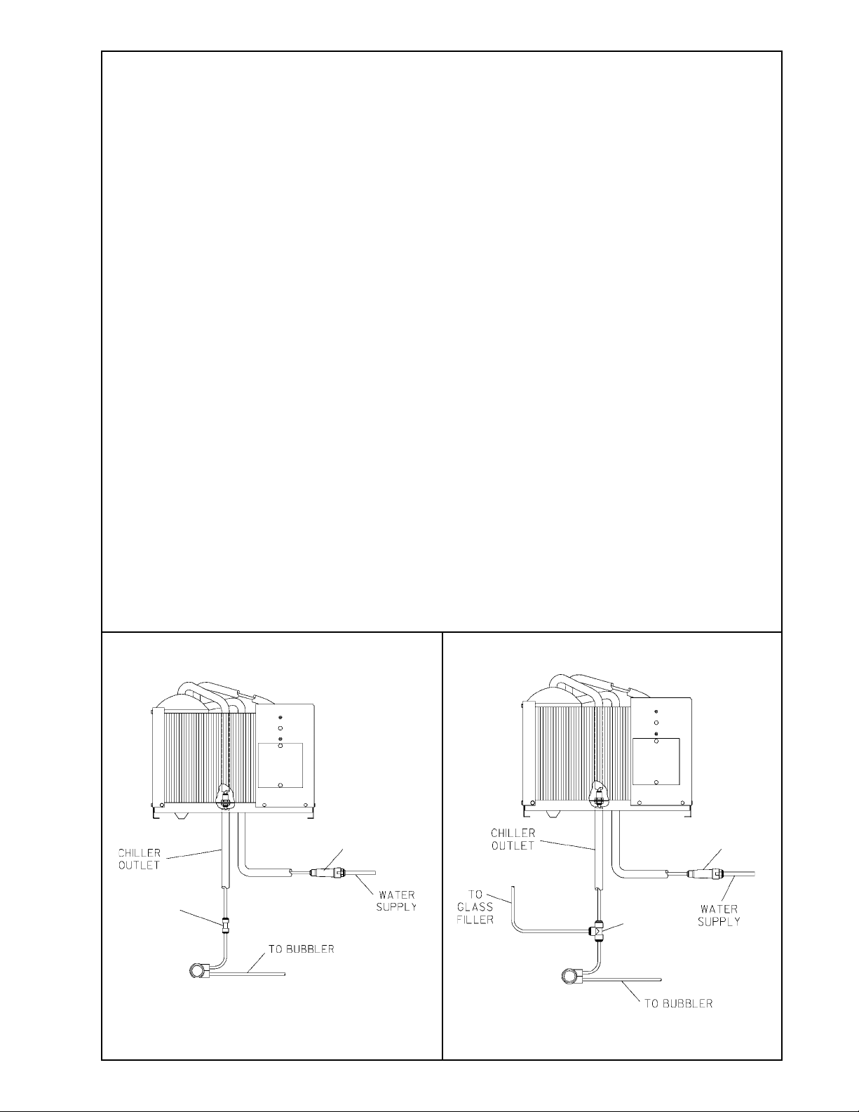
5. Connect water outlet tube on refrigeration package to water in tube on regulator holder (Item 19) with tubing and fitting
provided. (See Fig. 2)
** For glassfiller models see fig. 3.
6. Water inlet is 3/8" O.D. and waste tube is 1-1/4" O.D. Contractor is to supply waste trap and service stop valve in
accordance with local codes.
7. Connecting lines to be unplated copper and thoroughly flushed to remove all foreign matter before connecting to refrigeration
package. The furnished strainer (Item 28) should be added to the supply line.
8. Connect the refrigeration package to the supply line with a shut off valve and install a 3/8" (10mm) unplated copper water line
between the valve and the cooler. Remove burrs from outside of waterline. Insert water line straight into the fittings until they
reach a positive stop, approximately 3/4". (See Figs. 6 and 7) DO NOT SOLDER TUBES INSERTED INTO THE STRAINER AS
DAMAGE TO THE O-RINGS MAY RESULT.
9. Electrical: Insure power supply is identical in voltage, hertz, and phase to that specified on the refrigeration package serial
plate. Never wire compressor directly to the power supply.
10. Turn water supply on and check thoroughly for leaks.
11. Release air from tank by depressing push bar; a steady stream of water assures all air is removed.
12. Re-check for leaks.
13. Stream height is factory set at 35 PSI. If supply pressure varies greatly from this, turn adjustment screw on regulator (Item
22). Clockwise adjustment will raise the stream height and counter-clockwise adjustment will lower stream height. For best
adjustment, stream should hit basin approximately 6-1/2" from the bubbler.
14. Rotate fan blade on refrigeration package to insure proper clearance and free fan action.
15. Connect power supply.
16. Replace access panel and install grill using #8 x 1.00" (25mm) PH screws and small clips provided.
TROUBLE SHOOTING AND MAINTENANCE
1. Orifice Assy: Mineral deposits on orifice can cause water flow to spurt or not regulate. Mineral deposits may be removed
from orifice with a small round file not over 1/8 diameter or a small diameter wire. CAUTION: Do not file or cut orifice
materials.
2. Actuation of Quick Connect Water Fittings: Cooler is provided with lead-free connectors which utilize an o-ring water
seal. To remove tubing from the fitting, relieve water pressure, push in on the gray collar while pulling on the tubing (See Fig. 7).
To insert tubing, push tube straight into the fitting until it reaches a positive stop, approximatley 3/4".
3. CAUTION: Cleaning of Bronzetone models requires special care. Outer surfaces must be cleaned with a mild detergent or a
mixture of vinegar and water only, rinsed and wiped dry. Abrasive and acidic cleaners may eventually damage the Bronzetone
finish.
EHFRA7C EHFRA7FC
28
28
30
FIG. 3FIG. 2
PAGE 3
29
97160C (Rev. C - 10/02)
Page 4
10
11
12
13
14
15
16
17
18
19
20
21
22
23
24
25
26
27
28
29
30
31
32
33
34
35
36
37
EHFRA7C*A EHFRA7FC*A
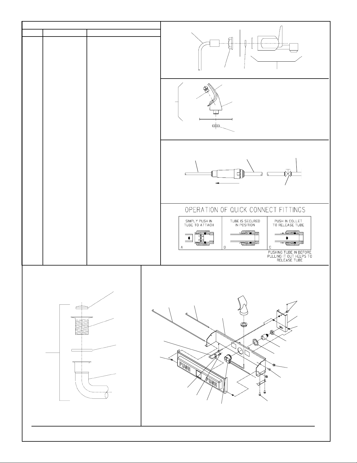
PARTS LIST
PART NO.ITEM NO.
1
2
3
4
5
6
7
8
9
15005C
21705C
21708C
21695C
21696C
31525028
40045C
40206000
40322C
40493C
72000833
40038C
40619C
40628C
50074C
55997C
50198C
56011C
50986C
56073C
55001089
EHFRADF
61314C
62084C
70002C
70012C
70278C
70378C
55996C
70682C
70683C
70379C
112627543890
75555C
EG25
74070030
74070032
74130045
DESCRIPTION
NUT - RETAINING
CLIP - PUSH ROD
PUSH BAR ASSY
BRKT - LEVER PUSH
BRKT - PUSH BAR MTG
O-RING
HEX NUT - UNPLTD
RETAINER
ORIFICE ASSY
GLASS FILLER
WASTE ARM ASSY
STRAINER
FERRULE
WASTE ARM
GASKET - TAILPIPE
PEDESTAL
BUSHING - SNAP
HOUSING ASSY
HOLDER - REGULATOR
BUBBLER ASSY
FOUNTAIN
FOUNTAIN W/GF
REGULATOR
TUBE ASSY - GF
SCREW-#10 X .50 HHSM
NUT - 3/8-18 LKNT
ROD - SUPPORT
ROD - PUSH
STRAINER
TEE - 1/4 (EHFRA7FC)
UNION- 1/4 (EHFRA7C)
ROD - PIVOT
SCREW - #10-24 X .50 PHTC
CLIP -.125 STUD LOCK
GRILL
SCREW - #8 X 1.00 PH
SPEED NUT #8
CLIP - TINNERMAN
FIG. 4
20
FIG. 5
FIG. 6
23
9
1/4" O.D. TUBE
WATER INLET
TO COOLER
25
18
16
25
3/8" O.D. UNPLATED
COPPER TUBE CONNECT
COLD WATER SUPPLY
NOTE: WATER FLOW
DIRECTION
106
NOTE: WHEN INSTALLING
REPLACEMENT BUBBLER
AND PEDESTAL, TIGHTEN
NUT (ITEM 25) ONLY TO HOLD
PARTS SNUG IN POSITION.
DO NOT OVER TIGHTEN.
BUILDING WATER
INLET
SERVICE STOP
(NOT FURNISHED)
12
13
15
27
11
17
14
FIG. 8 FIG. 9
FIG. 7
26
31
8
45
17
1
22
7
33
24
2
24
3
19
32
www.DrinkingFountainDoctor.com 800-518-5388
97160C (Rev. C - 10/02)
PAGE 4
 Loading...