

Page 1
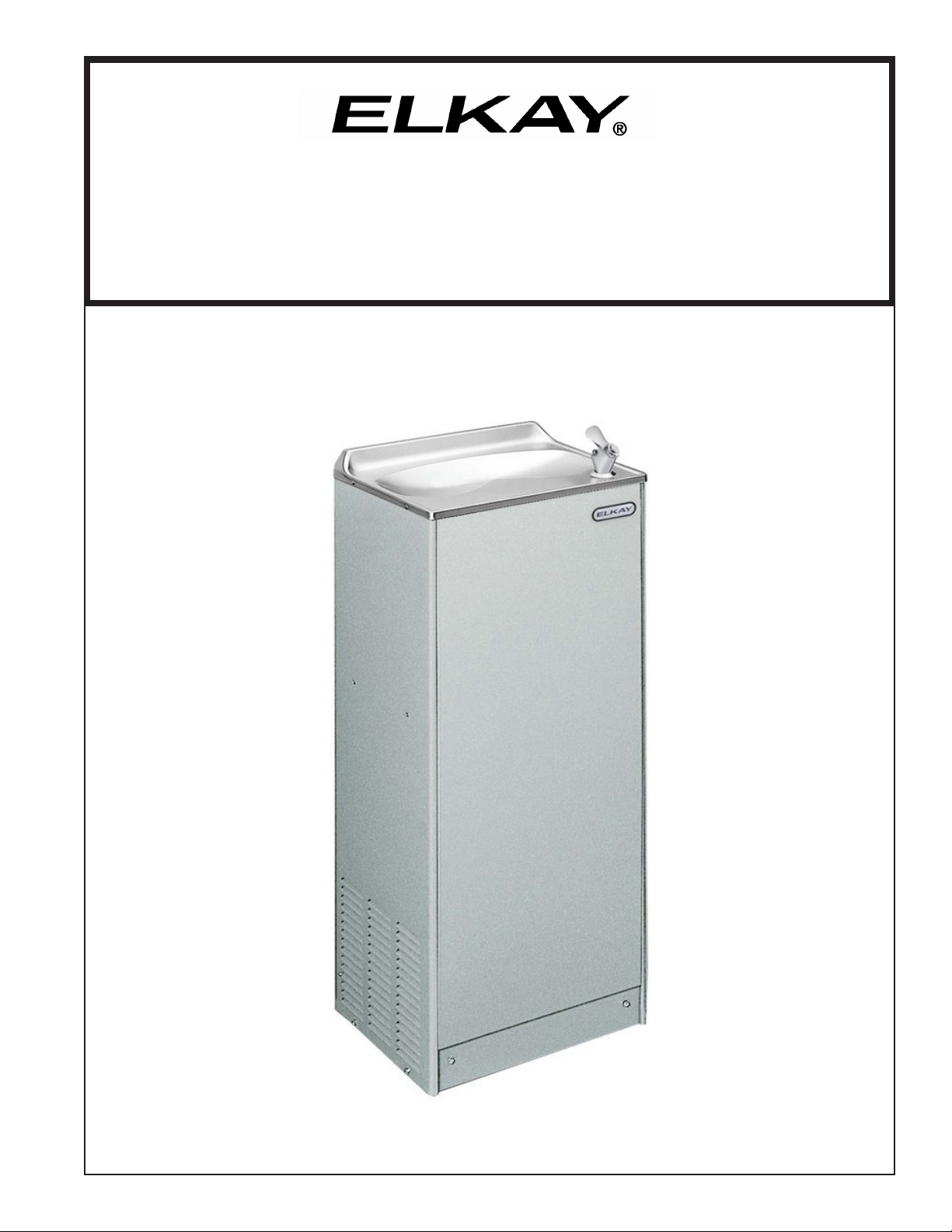
EFWC16*1
INSTALLATION, CARE & USE MANUAL
EFWC™ Series Barrier-Free Water Cooler
PAGE 1
97745C (Rev. G - 04/16)
Page 2
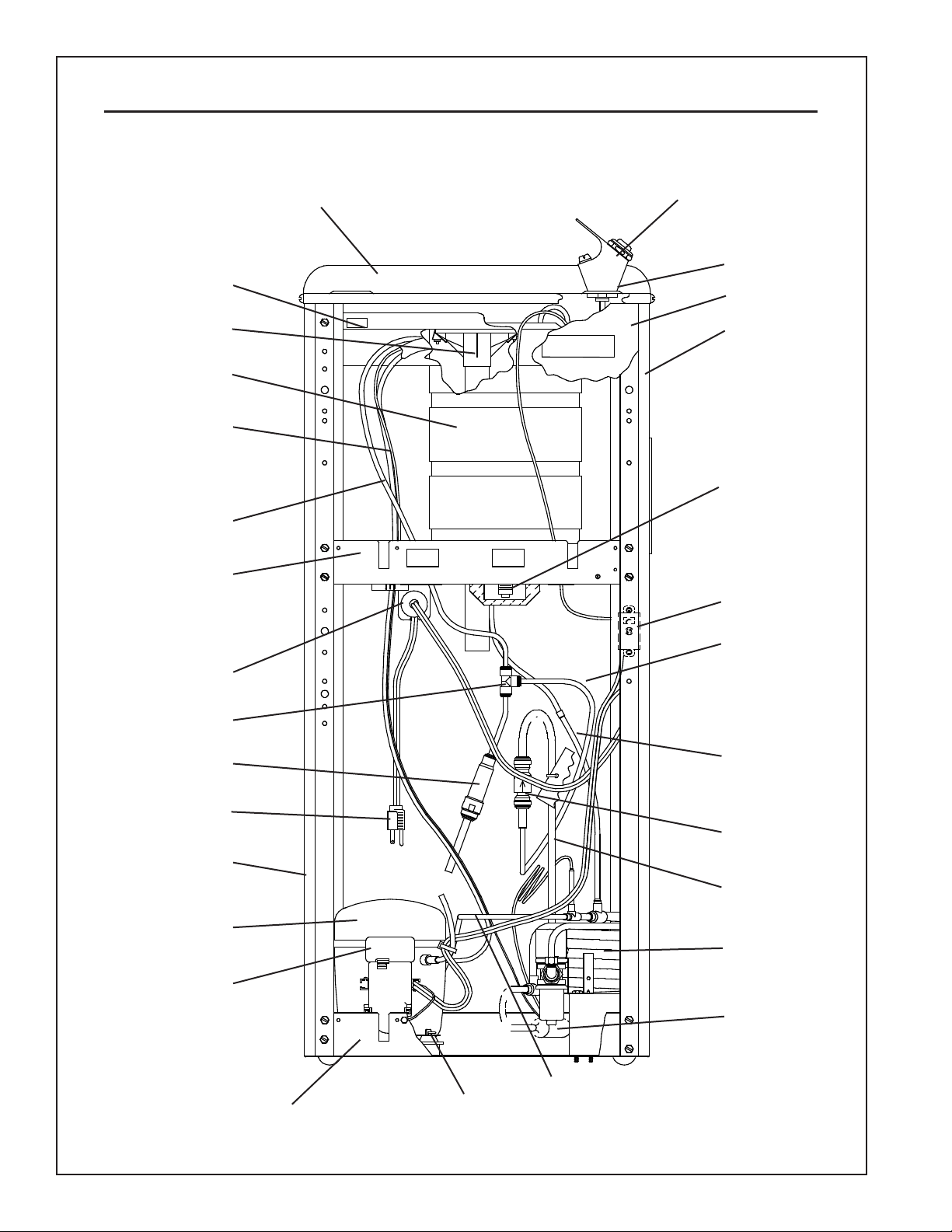
EFWC16*1
Note: Danger! Electric shock hazard. Disconnect power before servicing unit.
USES HFC-134A REFRIGERANT
5
6, 7
SEE FIG.5
3
11
28, 29, 31, 24, 27
35
34
40
10
25
33
13
4, 32
9
17
COLDER
39
38
14, 15, 18,
19, 20, 21, 22
97745C (Rev. G - 04/16)
16
12
23
30
42
37
36
41
8
26
FIG. 1
PAGE 2
Page 3
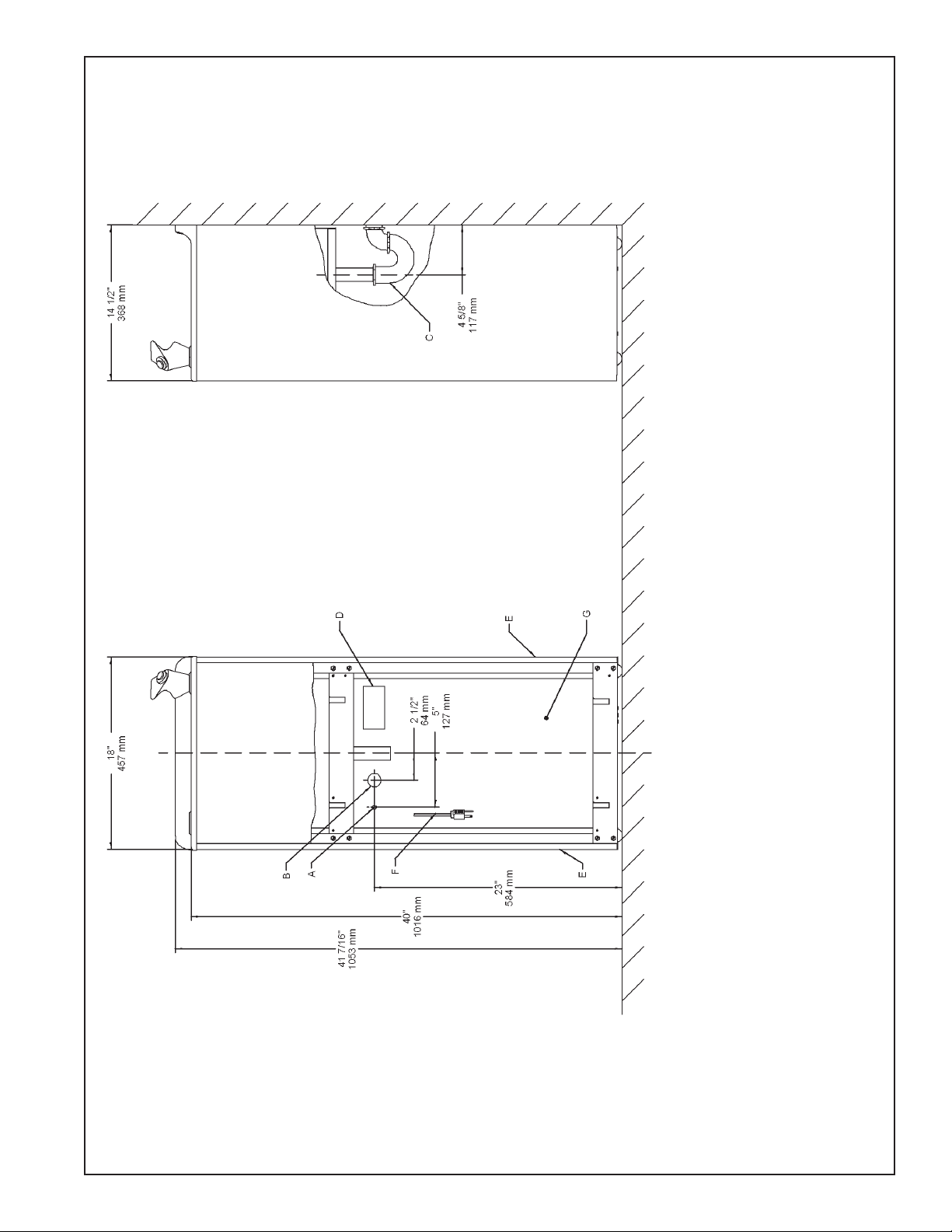
EFWC16*1
FINISHED FLOOR
FIG. 2
LEGEND/LEYENDA/LÉGENDE
A = RECOMMENDED WATER SUPPLY LOCATION 3/8 O.D. UNPLATED COPPER TUBE CONNECT STUB 1-1/2 IN. (38mm) OUT FROM WALL SHUT OFF BY OTHERS
B = RECOMMENDED LOCATION FOR WASTE OUTLET 1-1/4” O.D. DRAIN
C = 1-1/4 TRAP NOT FURNISHED**
D = ELECTRICAL OUTLET LOCATION
E = INSURE PROPER VENTILATION BY MAINTAINING 4" (102mm) (MIN.) CLEARANCE FROM CABINET LOUVERS TO WALL.
F = POWER CORD 4 FEET (1219mm) LONG
G = PLUMBING ROUGH-IN CAN BE LOCATED ANYWHERE WITHIN THIS AREA.
PAGE 3
97745C (Rev. G - 04/16)
Page 4
EFWC16*1
CONDENSER WATER VALVE ADJUSTMENT
The condenser water valve is factory preset for a condenser water outlet temperature of 95° to 105° F.
If actual temperature varies greatly from this, readjust
water ow rate at the valve using the following procedures.
1. START UP COMPRESSOR
This can be accomplished by depressing the cooler
push button. Keep water running during the entire
readjustment procedure.
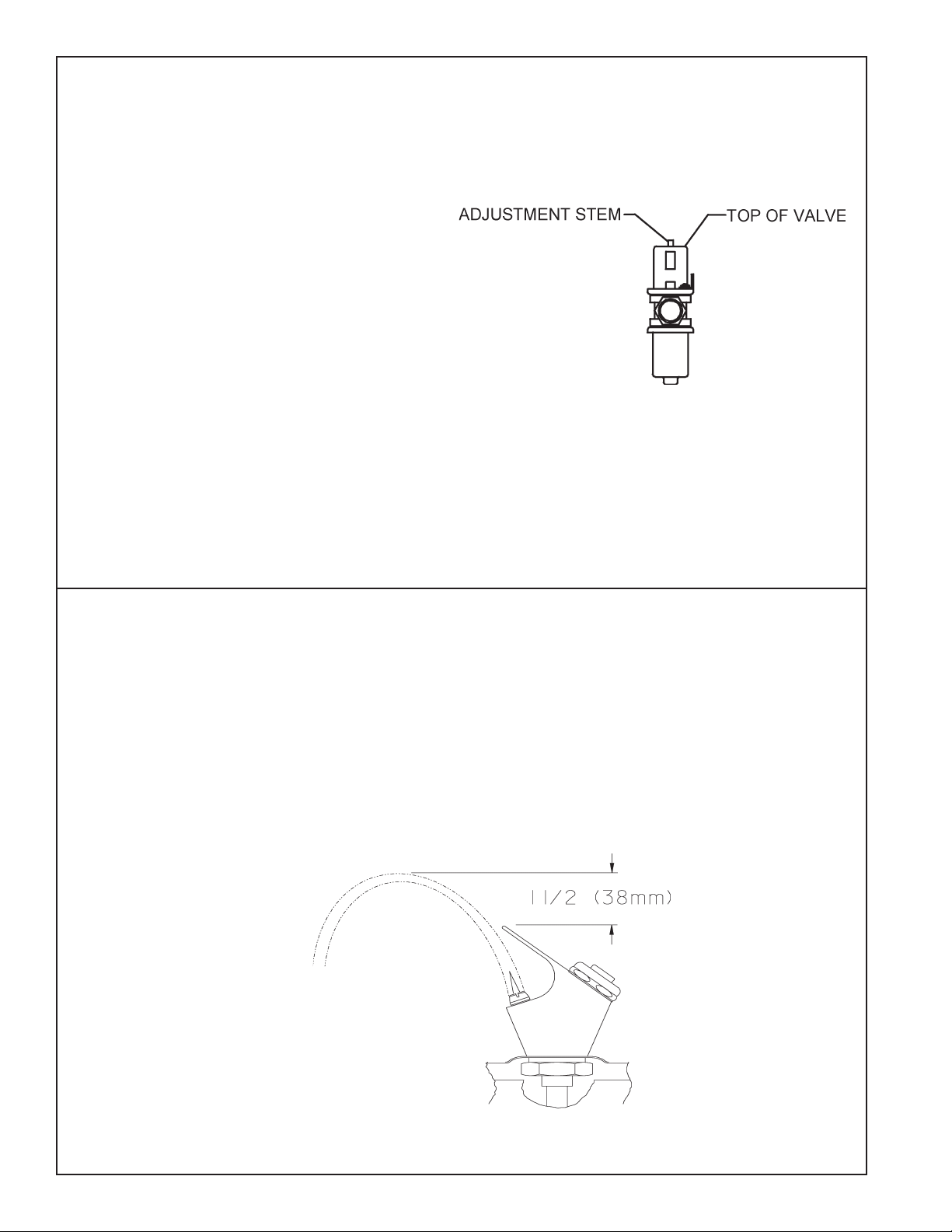
2. ADJUSTMENT CONDENSER WATER VALVE
Adjust valve by rotating adjustment stem. Rotating stem
clockwise will increase water ow. Counterclockwise
rotation will idecrease water ow. Increasing water
ow will result in a lower condenser outlet temperature,
while decreasing water ow will result in a higher outlet
temperature. Proper adjustment is attained when condenser outlet temperature is 95° to 105° F.
STREAM HEIGHT ADJUSTMENT: Stream height is factory set at
45-50 PSI. If supply pressure varies greatly from this, remove
items Cover Nut & Button (See gure 5) from bubbler assembly and
adjust the screw on the regulator (Item 35). Clockwise adjustment
will raise stream height and counterclockwise will lower the stream
height. A stream height of 1-1/2" (38mm) is recommended.
FIG. 3
97745C (Rev. G - 04/16)
FIG. 4
PAGE 4
Page 5
PARTS LIST 115V
EFWC16*1
ITEM NO.
1
2
3
4
5
6
7
8
9
10
11
12
13
14
15
16
17
18
19
20
21
22
23
24
25
26
27
28
29
30
31
32
33
34
35
36
37
38
39
40
41
42
*INCLUDES RELAY, OVERLOAD & CAPACITOR. IF UNDER
WARRANTY, REPLACE WITH SAME COMPRESSOR USED
IN ORIGINAL ASSEMBLY.
NOTE: All correspondence pertaining to any of the above
water coolers or orders for repair parts MUST include Model
No. and Serial No. of cooler, name and part number of re-
placement part.
PART NO. DESCRIPTION
1000002024
45703C
15009C
70772C
27317C
28270C
28271C
28272C
28273C
28631C
28277C
28278C
28279C
35843C
35840C
36219C
35892C
35768C
35845C
35874C
35844C
36095C
36318C
70750C
1000001994
0000000253
75603C
45718C
50005C
75494C
50368C
70767C
55996C
98849C
66685C
66203C
66802C
66677C
66693C
66679C
66680C
66681C
Kit - Bubbler Pushbutton
Bubbler Assy
Nipple-Bubbler
Drain Plug
Basin
Brace-Cross Rear
Brace-Cross Front
Baseplate
Shelf
Bracket-Strain Relief
Panel-Front
Panel-LH Side
Panel-RH Side
Relay
Overload
Cord-Power
Cold Control
Cover-Relay
Cap-Capacitor
Clip-Capacitor
Capacitor
Bracket-Capacitor
Compressor Service Pak
Hose Clamp
Kit - 1/4" Tee (3-Pack)
Kit - Compressor Mtg Hardware
Nut Hex SS
Assy-Tailpipe
Gasket-Tailpipe
Check Valve
Drain Receptor
Evaporator Retaining Clip
Strainer
Kit - Heat Exchanger/Drier
Assy-Evaporator
Drier
Assy-WC Condenser
Tube-WC Condenser
Tube-Tee To Check Vlv
Tube-CU 1/4 x 30
Tube-CU 1/4 x 22
Tube-Water Vlv To Check Vlv
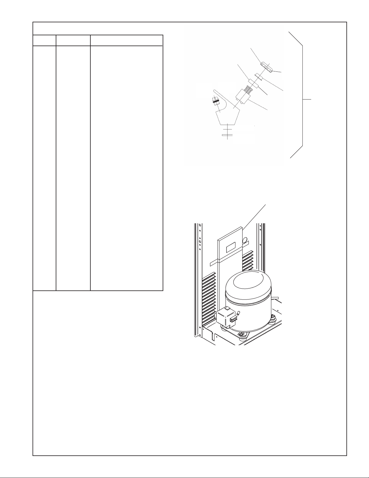
FIG. 5
1
1
COVER
NUT
BUTTON
NUT
REGULATOR
2
REMOVE THIS PACKING
BEFORE PUTTING UNIT
INTO SERVICE
PRINTED IN U.S.A.
FIG. 6
FOR PARTS, CONTACT YOUR LOCAL DISTRIBUTOR OR CALL 1.800.834.4816
ELKAY MANUFACTURING COMPANY • 2222 CAMDEN COURT • OAK BROOK, IL 60523 • 630.574.8484
REPAIR SERVICE INFORMATION TOLL FREE NUMBER 1.800.260.6640
PAGE 5
97745C (Rev. G - 04/16)
 Loading...