

Page 1
EDFP110/1 14/1 17C*A EDFPVR1 14C*A
Installation/Care/Use Manual
EDFP(W)110C EDFP(W)114C EDFP117C
®
Swirlflo
Fountains with FLEXI-GUARD
36
SEE FIG. 1 OR 2
32
35
SEE FIG. 8
EDFP(W)110/114C EDFP117C
Installer
T o assure you install this model easily and correctly , PLEASE READ THESE SIMPLE
INSTRUCTIONS BEFORE ST ARTING THE INST ALLATION. CHECK YOUR INST ALLATION FOR COMPLIANCE WITH PLUMBING, ELECTRICAL AND OTHER APPLICABLE
CODES. After installation, leave these instructions inside the fountain for future reference.
®
ALL SERVICE TO BE PERFORMED BY AN AUTHORIZED SERVICE PERSON
IMPORTANT! INSTALLER PLEASE NOTE.
THE GROUNDING OF ELECTRICAL EQUIPMENT SUCH AS TELEPHONE, COMPUTERS, ETC. T O WATER LINES
IS A COMMON PROCEDURE. THIS GROUNDING MA Y BE IN THE BUILDING OR MA Y OCCUR AW A Y FROM THE
BUILDING . THIS GROUNDING CAN CAUSE ELECTRICAL FEEDBACK INTO A FOUNTAIN, CREA TING AN ELECTROLYSIS WHICH CAUSES A MET ALLIC TASTE OR AN INCREASE IN THE METAL CONTENT OF THE WA TER.
THIS CONDITION IS A VOIDABLE BY USING THE PROPER MATERIALS AS INDICA TED. ANY DRAIN FITTINGS
PROVIDED BY THE INST ALLER SHOULD BE MADE OF PLASTIC TO ELECTRICALL Y ISOLA TE THE FOUNT AIN
FROM THE BUILDING PLUMBING SYSTEM.
IMPORTANT
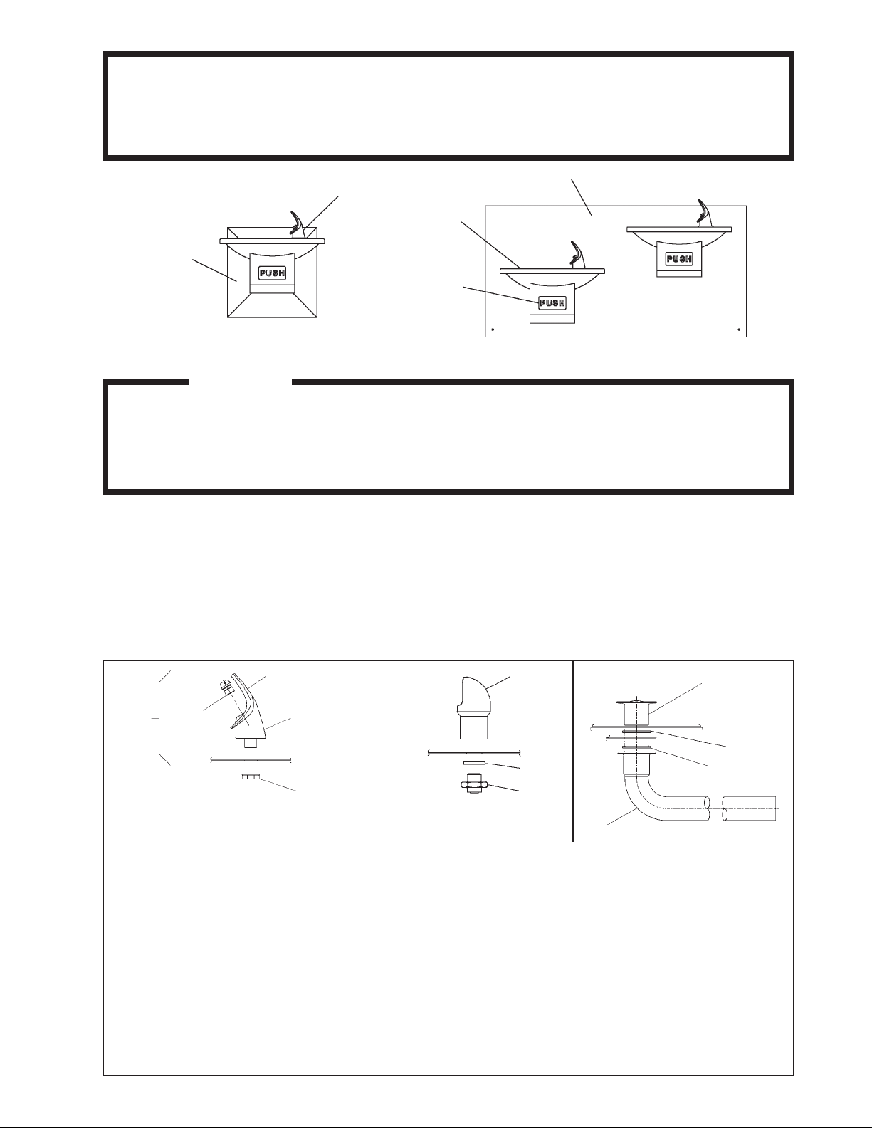
FIG. 1
28
29
30
31
16
NOTE: When installing replacement bubbler and pedestal, tighten
locknut (Item 16 or 38) only to hold parts snug in position.
DO NOT OVERTIGHTEN.
1. Wall should already be framed for the fountain using the positioning dimensions shown in Figures 4 or 5. Shown dimensions pertain to
installation location (framing must support up to 150 lbs. weight). These dimensions are required for compliance with ANSI Standard A117.0.
2. Install rough-in plumbing as shown in Figures 4 or 5. Run the supply water inlet line through the back panel. Install a service stop (not
provided). Turn on supply water and flush thoroughly.
3. Remove bottom access panel from fountain basin and save the screws. Install the fountain to the back panel and wall using (4) 5/16" nuts to
attach to the mounting bracket rods.
4. Determine required length of waste line and cut to appropriate length. 1-1/4" O.D. waste tube furnished. 1-1/4" slip trap, waste elbow and
extension not provided.
5. Make water supply connections from service stop to the 3/8" O.D. unplated copper tube coming out of the strainer. Turn on water supply and
check for leaks. Newly installed water supply line should be insulated after leak check is completed. DO NOT SOLDER TUBES INSERTED
INTO THE STRAINER AS DAMAGE TO THE O-RINGS MA Y RESUL T.
6. These products are designed to operate on 20-105 PSIG supply line pressure. If inlet pressure is above 105 PSIG, a pressure regulator must be
installed in the supply line. Any damage caused by reason of connecting these products to supply line pressures lower than 20 PSIG or higher
than 105 PSIG is not covered by warranty.
7. Check stream height from bubbler. Stream height is factory set at 35 PSI. If supply pressure varies greatly from this, turn adjustment screw
on the regulator (Item 14). Clockwise adjustment will raise stream height and counter-clockwise will lower stream height. For best adjustment
stream should hit basin approximately 6-1/2" (165mm) from bubbler.
8. Replace bottom access panel to fountain using the screws provided. Tighten securely.
FIG. 2
INSTALLA TION INSTRUCTIONS
39
37
38
FIG. 3
9
23
10
12
97108C (Rev. M - 12/04)
Page 2
EDFP110/1 14/117C*A EDFPVR1 14C*A
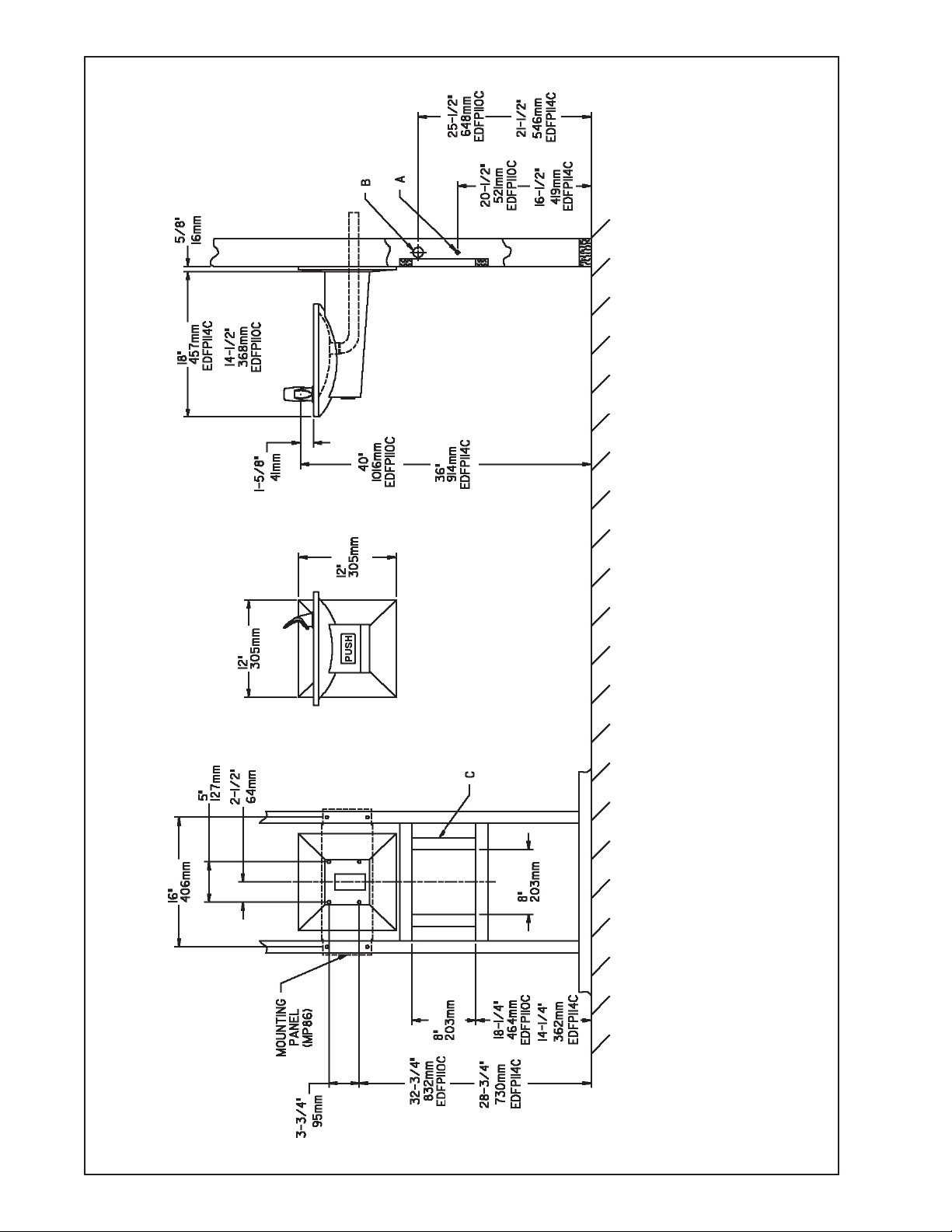
EDFP(W)1 10/1 14C ROUGH-IN
FIG. 4
FINISHED FLOOR
97108C (Rev. M - 12/04)
PAGE 2
LEGEND:
A = WA TER INLET LOCA TION LEFT OR RIGHT SIDE. 3/8” O.D. UNPLA TED COPPER TUBE CONNECT.
B = FOUNT AIN WASTE LOCA TION LEFT OR RIGHT SIDE. WASTE IS SHOWN IN W ALL
BUT MA Y BE BEHIND WALL. 1-1/4” O.D. DRAIN (TRAP NOT FURNISHED).
C = FRAMING REQUIRED WHEN OPTIONAL AP-99 ACCESS P ANEL IS USED.
Page 3

EDFP110/1 14/1 17C*A EDFPVR1 14C*A
EDFP1 17C ROUGH-IN
FINISHED FLOOR
FIG. 5
PAGE 3
LEGEND:
A = WA TER INLET LOCATION LEFT OR RIGHT SIDE. 3/8” O.D. UNPLA TED COPPER TUBE CONNECT.
B = FOUNT AIN WASTE LOCA TION LEFT OR RIGHT SIDE. WASTE IS SHOWN IN W ALL
BUT MA Y BE BEHIND WALL. 1-1/4” O.D. DRAIN (TRAP NOT FURNISHED).
C = FRAMING REQUIRED WHEN OPTIONAL AP-99 ACCESS P ANEL IS USED.
D = 3/16" DIA. (5mm) HOLES.
E = 3/8" DIA. (10mm) HOLES.
97108C (Rev. M - 12/04)
Page 4

ITEM NO.
1
2
3
4
5
6
7
8
9
10
11
12
13
14
15
16
17
18
19
20
21
22
23
24
25
26
27
28
29
30
31
32
33
34
35
36
37
38
39
NS
NS
PART NO.
15005C
21705C
28321C
28322C
28324C
28325C
40045C
40206000
45330C
50074C
50198C
50377C
50986C
61313C
70002C
75580C
70208C
70378C
70410C
70425C
75555C
21810C
45336C
21822C
21823C
21845C
21846C
56073C
40322C
56011C
55997C
55001026
70055C
112627543890
55000940
55000941
100322740560
15009C
98118C
55996C
56092C
EDFP110/1 14/117C*A EDFPVR1 14C*A
PAR TS LIST
DESCRIPTION
RETAINING NUT
CLIP-PUSH ROD
REGULATOR MOUNTING BRACKET
PUSH BAR MOUNTING BRACKET
REGULATOR ACTIV A TING ARM
PIVOT ROD BRACKET
HEX NUT
RETAINER
WASTE ARM TUBE
GASKET-TAILPIPE
BUSHING-SNAP
GASKET-TAILPIPE
REGULATOR HOLDER
REGULATOR
SCREW-#10 X .50 HHSM
NUT-3/8-18 LKNT
SCREW -#10-24 X .38 PHTC
ROD-PUSH
ROD-PIVOT
ROD-PIVOT
CLIP-.125 STUD LOCK
PUSH BAR ASSY
STRAINER & FERRULE ASSY
FTN BODY & SHELL ASSY (EDFP110C)
FTN BODY & SHELL ASSY (EDFP114C)
COVER PLATE (EDFP1 10C)
COVER PLATE (EDFP1 14C)
BUBBLER ASSY
ORIFICE ASSY
HOUSING ASSY
PEDESTAL
BASIN
NUT-SPEED
SCREW-#8-32 X .25 THMS
BACK PANEL ASSY (EDFPW110/114C)
BACK PANEL ASSY (EDFP117C)
GASKET (VR MODEL ONL Y)
NIPPLE - BUBBLER (VR MODEL ONLY)
BUBBLER ASSEMBL Y (VR MODEL ONL Y)
STRAINER
POLY TUBING (CUT TO LENGTH)
FIG. 6
1/4" O.D. TUBE
WATER INLET
TO COOLER
3/8" O.D. UNPLATED
COPPER TUBE CONNECT
COLD WATER SUPPL Y
NOTE: WA TER FLOW
DIRECTION
BUILDING WATER INLET
SERVICE STOP
(NOT FURNISHED)
FIG. 7
TROUBLE SHOOTING AND MAINTENANCE
1. Orifice Assy: Minerals deposits on orifice can cause water flow
to spurt or not regulate. Mineral deposits may be removed from the
orifice with a small round file not over 1/8" diameter or a small
diameter wire.
CAUTION: Do not file or cut orifice materials.
2. Stream Regulator: If orifice is free of material deposits regulate
water flow according to instructions on page 1.
FIG. 8
34
21
SEE FIG . 3
24
25
1
26, 33, 34
11
5
8
11
22
11
18
27, 33, 34
8
14
15
7
3
4
11
19
2
11
13
ELKAY MANUFACTURING COMP AN Y • 2222 CAMDEN COURT • OAK BROOK, IL 60523 • 630.574.8484
97108C (Rev. M - 12/04)
11
17
15
6
20
FOR PARTS, CONT ACT YOUR LOCAL DISTRIBUTOR OR CALL 1.800.323.0620
PAGE 4
 Loading...