

Page 1
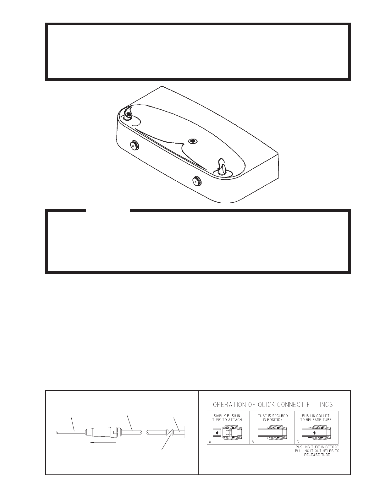
EDFP220RC EDFPVR220RC
Installation/Care/Use Manual
Composite Fountain with FLEXI-GUARD
®
Installer
T o assure you install this model easily and correctly ,
PLEASE READ THESE SIMPLE INSTRUCTIONS BEFORE ST ARTING THE
INST ALLATION. CHECK YOUR INST ALLA TION FOR COMPLIANCE WITH
PLUMBING , ELECTRICAL AND OTHER APPLICABLE CODES. After installation, leave
these instructions inside the fountain for future reference.
IMPORTANT
ALL SERVICE TO BE PERFORMED BY AN AUTHORIZED SERVICE PERSON
IMPORTANT! INSTALLER PLEASE NOTE.
THE GROUNDING OF ELECTRICAL EQUIPMENT SUCH AS TELEPHONE, COMPUTERS, ETC. TO
WA TER LINES IS A COMMON PROCEDURE. THIS GROUNDING MA Y BE IN THE BUILDING OR MA Y
OCCUR A WA Y FROM THE BUILDING . THIS GROUNDING CAN CAUSE ELECTRICAL FEEDBACK
INTO A FOUNT AIN, CREA TING AN ELECTROL YSIS WHICH CAUSES A MET ALLIC T ASTE OR AN
INCREASE IN THE METAL CONTENT OF THE WATER. THIS CONDITION IS A VOIDABLE BY USING
THE PROPER MA TERIALS AS INDICA TED. ANY DRAIN FITTINGS PROVIDED BY THE INST ALLER
SHOULD BE MADE OF PLASTIC TO ELECTRICALL Y ISOLA TE THE FOUNT AIN FROM THE BUILDING
PLUMBING SYSTEM.
1/4" O.D. TUBE
WATER INLET
TO COOLER
3/8" O.D. UNPLATED
COPPER TUBE CONNECT
COLD WATER SUPPL Y
NOTE: WA TER FLOW
DIRECTION
BUILDING WAT ER
INLET
SERVICE STOP
(NOT FURNISHED)
FIG. 2FIG. 1
97296C (REV . L - 4/05)
Page 2
EDFP220RC EDFPVR220RC
FIG. 3
97296C (REV . L - 4/05)
PAGE 2
LEGEND
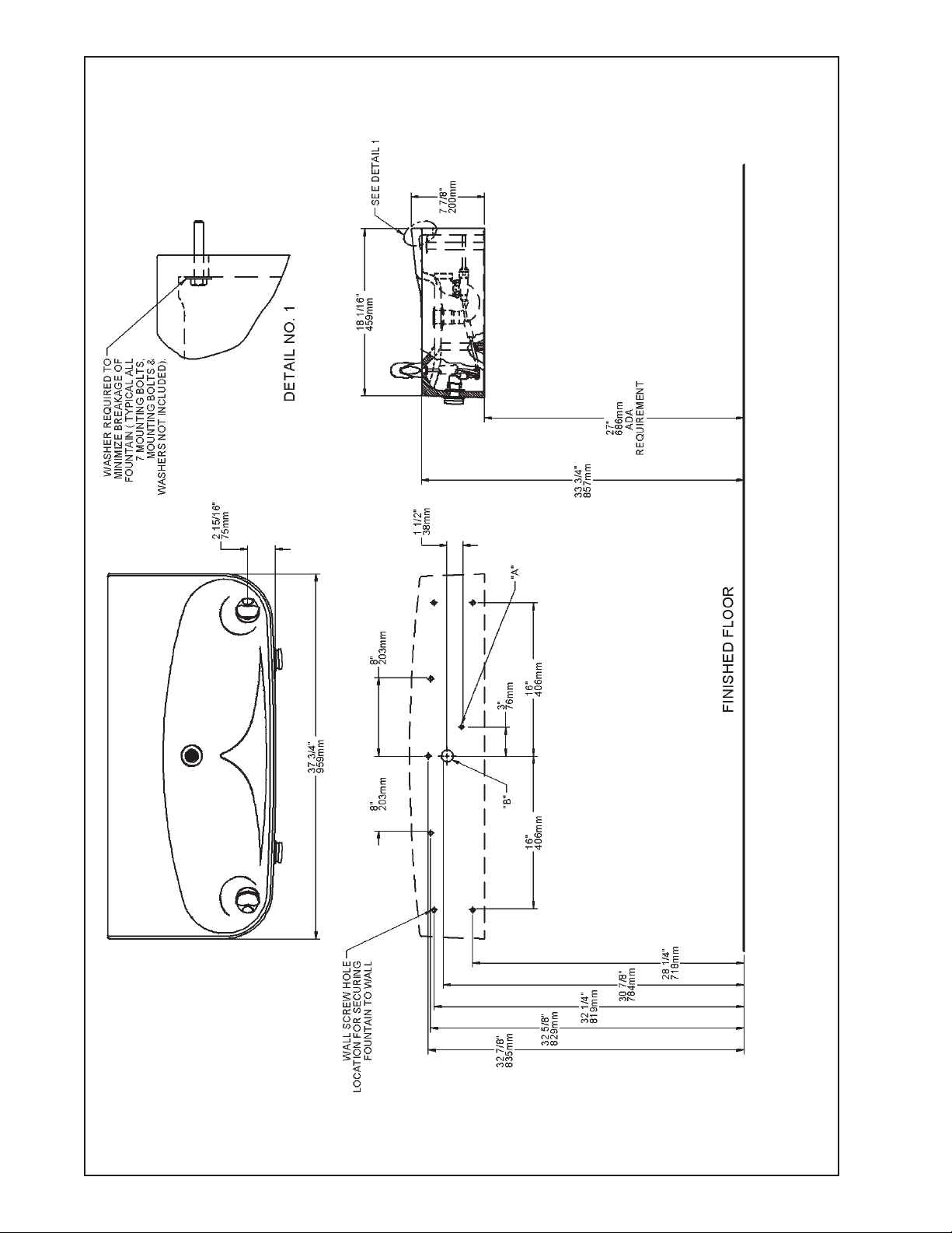
A = 3/8" O.D. UNPLA TED COPPER TUBE CONNECT - SHUT OFF V AL VE BY OTHERS
B = WATER OUTLET 1-1/4" O.D. DRAIN - STUB OUT FROM WALL 1" (25mm)
Page 3
EDFP220RC EDFPVR220RC
713
17
SEE FIG. 6 OR 7
14
SEE FIG . 8
3SEE FIG. 5
FIG. 4
INST ALLATION INSTRUCTIONS
1. Wall should already be framed for the fountain using the positioning dimensions shown in Figure 3. Shown dimensions pertain to
installation location (framing must support up to 150 lbs. weight). These dimensions are required for compliance with ANSI Standard A117.0.
2. Install rough-in plumbing as shown in Figure 3. Run the supply water inlet line and connect to a service stop (not provided). Turn on supply
water and flush thoroughly.
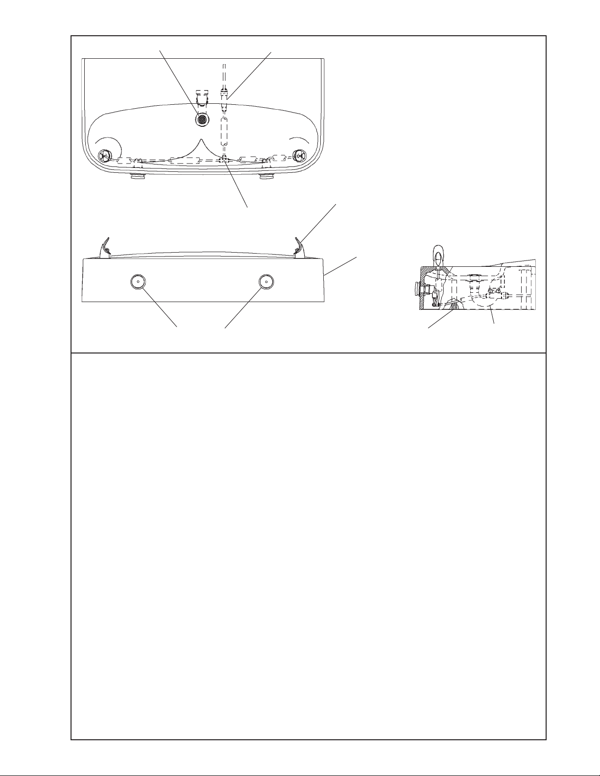
3. Remove bottom access panel from fountain basin and save the screws. Install the fountain to the wall using (7) 5/16" bolts and washers (not
provided). Bolts should be long enough to securely fasten the fountain to the wall. Tighten securely, but do not over tighten. Over tightening will
crack the fountain.
4. Remove elbow from end of p-trap and attach it to drain tube. Reattach elbow to p-trap and cut waste tube to required length using plumbing
hardware and trap as a guide.
5. Make water supply connections from service stop to the 3/8" O.D. unplated copper tube coming out of the strainer. Turn on water supply and
check for leaks. Newly installed water supply line should be insulated after leak check is completed. DO NOT SOLDER TUBES INSERTED INTO
THE STRAINER AS DAMAGE TO THE O-RINGS MA Y RESULT.
6. These products are designed to operate on 20-105 PSIG supply line pressure. If inlet pressure is above 105 PSIG, a pressure regulator must be
installed in the supply line. Any damage caused by reason of connecting these products to supply line pressures lower than 20 PSIG or higher
than 105 PSIG is not covered by warranty.
7. Check stream height from bubbler. Stream height is factory set at 35 PSI. If supply pressure varies greatly from this, adjust the screw on the
regulator (Item 15), by using a small screw driver through the small hole in the push button (Item 8). Clockwise adjustment will raise stream height
and counter-clockwise will lower stream height. For best adjustment stream should hit basin approximately 6-1/2" (165mm) from bubbler.
8. Replace bottom access panel to fountain using the screws provided. Tighten securely.
CARE AND MAINTENANCE OF ELKA Y COMPOSITE FOUNT AINS
1. Elkay composite fountains provide an extremely durable, nonporous surface which resists staining. Care is very simple. Routine cleaning with a
soft sponge or cloth, or with water or a non-abrasive aerosol foam cleaner, is all that is normally needed to give many years of trouble free
service. Cleaners left standing on the fountain surface can dull the surface finish. Be certain to rinse all cleaning agents completely and polish
with a soft cloth.
2. Harsh abrasive cleaners are not required and should not be used.
3. Mild abrasives such as liquid automotive cleaning compound or baking soda paste will remove simple scratches and stains. Cigarette burns can
normally be removed without noticeable effect. Deeper scratches or gouges can be corrected with fine grit sandpaper (240 grit then 400 grit) or a
green scotchbrite pad.
4. To maintain or regain luster and make cleaning easier, periodic applications of automobile wax or like products will keep the finish looking like new.
TROUBLE SHOOTING AND MAINTENANCE
1. Orifice Assy: Mineral deposits on orifice can cause water flow to spurt or not regulate. Mineral deposits may be removed from orifice with a
small round file not over 1/8" diameter or a small diameter wire.
CAUTION: Do not file or cut orifice materials.
2. Stream Regulator: If orifice is free of material deposits, regulate flow according to instruction 7 stated above.
3. Actuation of Quick Connect Water Fittings: Cooler is provided with lead-free connectors which utilize an o-ring water seal. To remove tubing
from the fitting, relieve water pressure, push in on the gray collar while pulling on the tubing (See Figure 2). To insert tubing, push tube straight
into the fitting until it reaches a positive stop, approximately 3/4".
PAGE 3
97296C (REV . L - 4/05)
Page 4
10
11
12
13
14
15
16
17
18
19
20
21
22
23
24
25
NS
EDFP220RC EDFPVR220RC
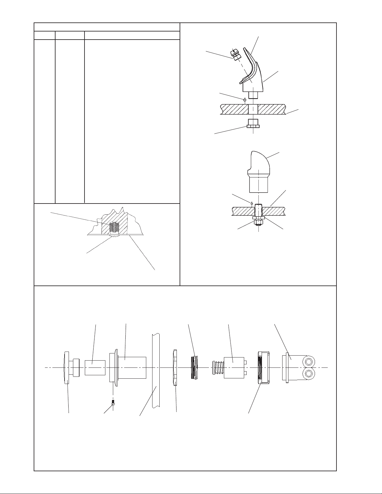
PAR TS LIST
PAR T NO.ITEM NO.
40322C
1
55998C
2
3
4
5
6
7
8
9
LK464
15005C
27635C
40045C
45391C
45662C
45738C
50986C
56011C
56087C
55996C
56046C
61313C
75672C
70682C
75534C
75553C
75554C
98118C
75575C
70012C
45736C
15029C
56092C
ORIFICE ASSEMBLY
BUBBLER PEDESTAL
DRAIN
REGULAT OR EXTENSION NUT
BOTTOM COVER
HEX NUT
DRAIN FERRULE
PUSH BUTTON
PUSH BUTTON SLEEVE
REGULAT OR HOLDER
BUBBLER HOUSING
PUSH BUTTON EXTENSION
STRAINER
BASIN
REGULAT OR
SCREW - CAP #6-32 X 5/16
TEE - 1/4
SCREW - #10-24 PINNED TORX
HEX NUT - 3/8-18
THREADED INSERT
BUBBLER ASSY (VR MODEL ONL Y)
BALL - ANTI-ROT A TIONAL
NUT - LOCK 3/8-18 (VR MODEL ONLY)
NUT - REGULA TOR MOUNTING
NIPPLE ASSEMBL Y
POLY TUBING (CUT TO LENGTH)
DESCRIPTION
FIG. 6
1
22
19
FIG. 7
22
11
2
BASIN
21
BASIN
20
FIG. 5
FIG. 8
18
12
25
NOTE: WHEN INSTALLING REPLACEMENT
BUBBLER AND PEDESTAL, TIGHTEN NUT
5
910
4
(ITEM 19 OR 23) ONLY TO HOLD P ARTS
SNUG IN POSITION.
DO NOT OVER TIGHTEN.
15
23
8
97296C (REV . L - 4/05)
16
BASIN
6
24
www.DrinkingFountainDoctor.com 800-518-5388
PAGE 4
 Loading...