

Page 1
EDFPA17FPC
Installation/Care/Use Manual
EDFPA17FPC
Freeze Resistant Fountain
EDFPA17FPC
Installer
To assure you install this model easily and correctly, PLEASE READ THESE SIMPLE
INSTRUCTIONS BEFORE STARTING THE INSTALLATION. CHECK YOUR INSTALLATION FOR COMPLIANCE WITH PLUMBING, ELECTRICAL AND OTHER APPLICABLE
CODES. After installation, leave these instructions inside the fountain for future reference.
This Freeze Resistant Fountain is shipped in two separate cartons. The second carton
contains the Freeze Resistant Package LK616A that is installed on an interior heated
wall. Refer to the Freeze Resistant Package for the rough-in dimensions for installation.
IMPORTANT
ALL SERVICE TO BE PERFORMED BY AN AUTHORIZED SERVICE PERSON
IMPORTANT! INSTALLER PLEASE NOTE.
THE GROUNDING OF ELECTRICAL EQUIPMENT SUCH AS TELEPHONE, COMPUTERS, ETC. TO
WATER LINES IS A COMMON PROCEDURE. THIS GROUNDING MAY BE IN THE BUILDING OR MAY
OCCUR AWAY FROM THE BUILDING. THIS GROUNDING CAN CAUSE ELECTRICAL FEEDBACK
INTO A FOUNTAIN, CREATING AN ELECTROLYSIS WHICH CAUSES A METALLIC TASTE OR AN
INCREASE IN THE METAL CONTENT OF THE WATER. THIS CONDITION IS AVOIDABLE BY USING
THE PROPER MATERIALS AS INDICATED. ANY DRAIN FITTINGS PROVIDED BY THE INSTALLER
SHOULD BE MADE OF PLASTIC TO ELECTRICALLY ISOLATE THE FOUNTAIN FROM THE BUILDING
PLUMBING SYSTEM.
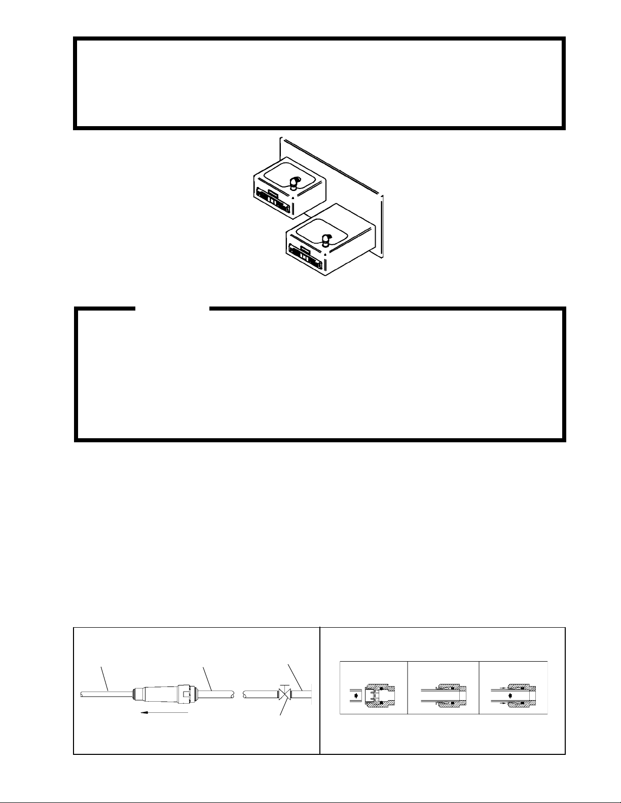
1/4" O.D. TUBE
WATER INLET
TO COOLER
FIG. 1
3/8" O.D. UNPLATED
COPPER TUBE CONNECT
COLD WATER SUPPLY
NOTE: WATER FLOW
DIRECTION
BUILDING WATER
INLET
SERVICE STOP
(NOT FURNISHED)
OPERATION OF QUICK CONNECT FITTINGS
SIMPLY PUSH IN
TUBE TO ATTACH
TUBE IS
SECURED
IN POSITION
PUSH IN COLLET
TO RELEASE TUBE
PUSHING TUBE IN BEFORE
PULLING IT OUT HELPS TO
RELEASE TUBE
FIG. 2
97728C (Rev. A - 12/02)
Page 2
EDFPA17FPC
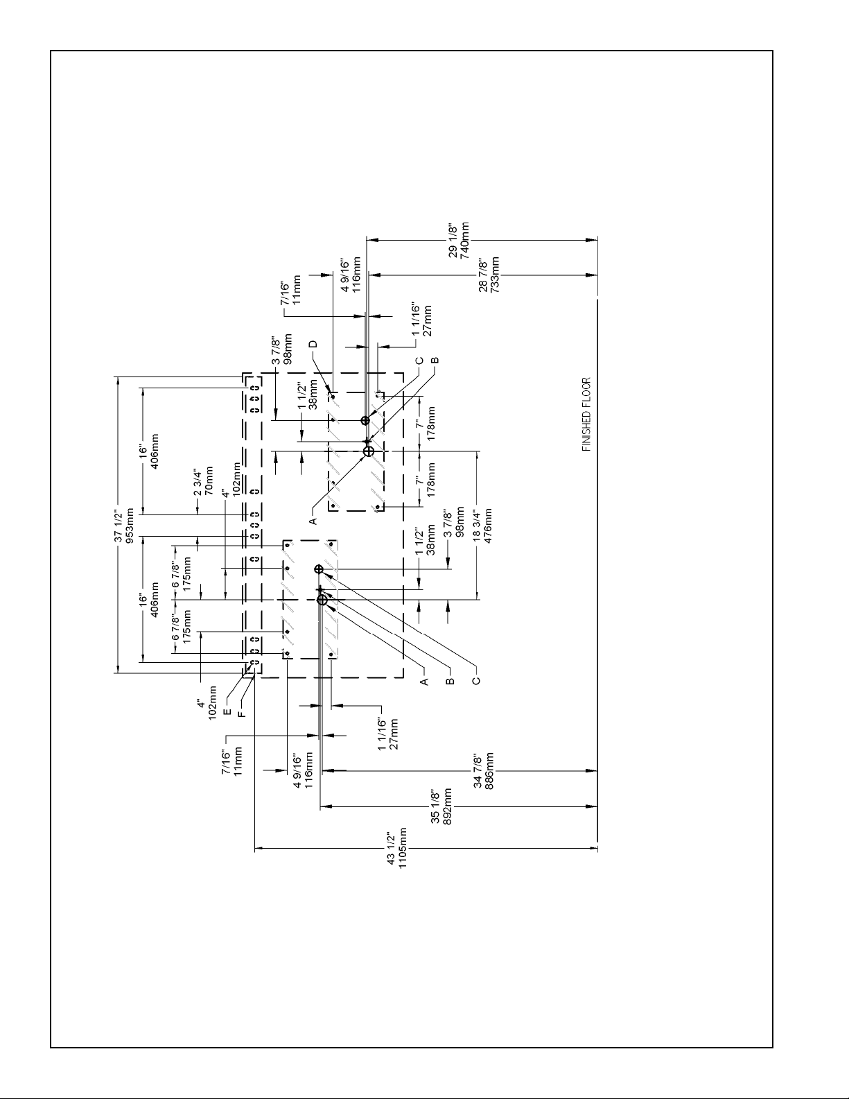
NOTE: REINFORCE WALL IN SHADED AREAS.
EDFPA17FPC ROUGH-IN
97728C (Rev. A - 12/02)
FIG. 3
PAGE 2
LEGEND:
A = 1-3/4" (44mm) DIA. HOLE FOR WASTE LINE
B = 7/8" (22mm) DIA. HOLE FOR WATER SUPPLY TUBE
C = 1" (25mm) DIA. HOLE FOR PUSH ROD
D = 1/4" (6mm) DIA. HOLE FOR MOUNTING FOUNTAIN TO WALL
E = 5/16" (8mm) DIA. HOLE FOR MOUNTING HANGER TO WALL
F = WALL HANGER FURNISHED LOOSE
*Note: All dimensions are taken from the finished floor on the side of the wall
that the fountain is installed on.
Page 3
EDFPA17FPC
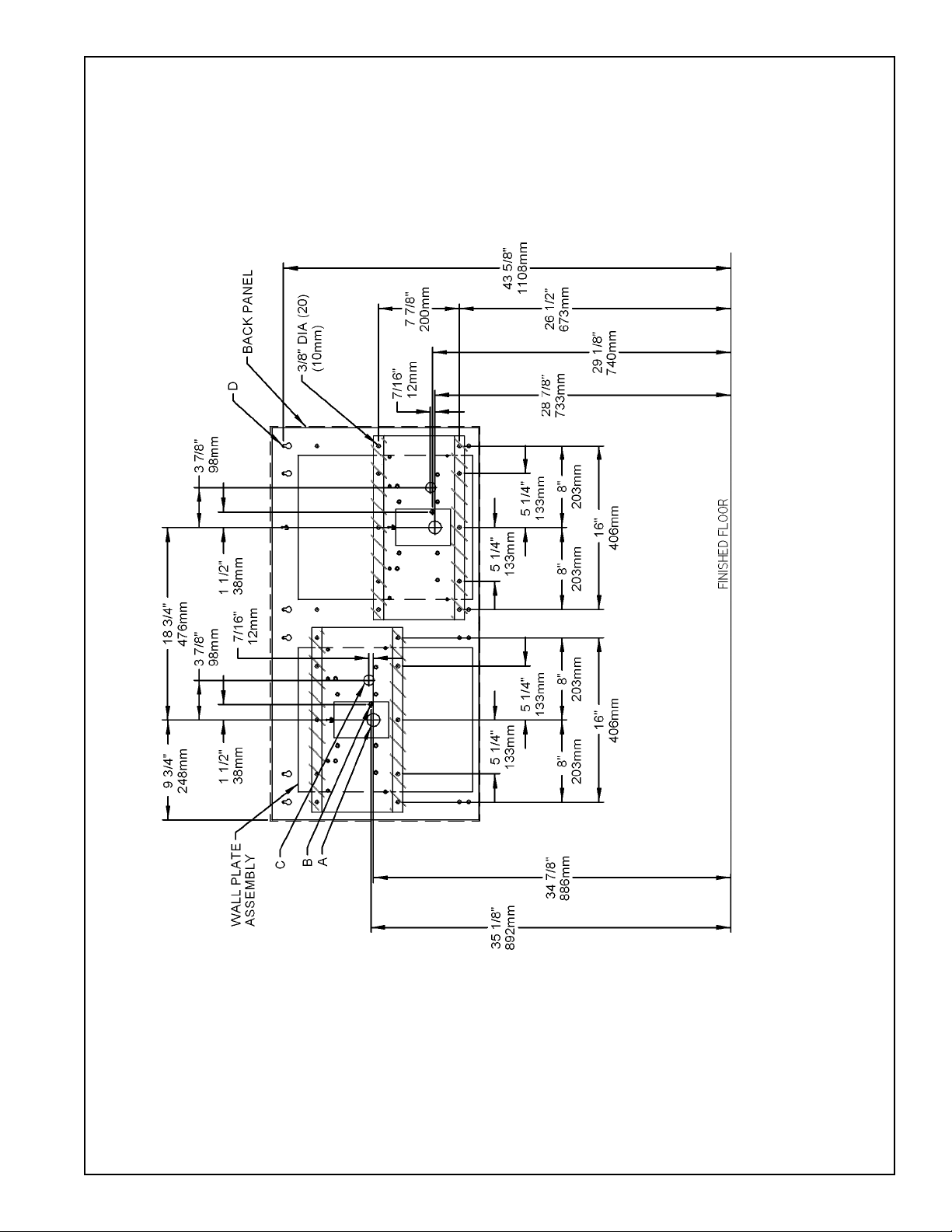
NOTE: REINFORCE WALL IN SHADED AREAS.
EDFPA17FPC W/MOUNTING PLATE ROUGH-IN
FIG. 4
PAGE 3
LEGEND:
A = 1-3/4" (44mm) DIA. HOLE FOR WASTE LINE
B = 7/8" (22mm) DIA. HOLE FOR WATER SUPPLY TUBE
C = 1" (25mm) DIA. HOLE FOR PUSH ROD
D = 1/4" (6mm) DIA. HOLE FOR MOUNTING PLATE TO WALL
97728C (Rev. A - 12/02)
*Note: All dimensions are taken from the finished floor on the side of the wall
that the fountain is installed on.
Page 4

EDFPA17FPC
EDFPA17FPC ROUGH-IN
97728C (Rev. A - 12/02)
FIG. 5
PAGE 4
Page 5

EDFPA17FPC
FIG.7
FIG. 6
16
Installing back panel: When installing back panel without mounting plate accessory, attach (4) channel braces
as shown in Fig. 7. Remove the protective backing from the tape installed on the brace. Line up the corresponding
holes in the brace and back panel and press firmly in place.
PAGE 5
97728C (Rev. A - 12/02)
Page 6

EDFPA17FPC
INSTALLATION INSTRUCTIONS
1. Wall should already be framed for the fountain using the positioning dimensions shown in Figure 3 or 4. Shown
dimensions pertain to installation location (framing must support up to 300 lbs. weight). These dimensions are
required for compliance with ANSI Standard A117.1/ADA requirements.
2. Install back panel.
EDFPA17FPC: Place the upper edge of the panel above hanger bracket.
EDFPA17FPC W/MOUNTING PLATE: Place the upper edge of the panel above mounting plate on the wall.
Slide the panel down until it engages the mounting plate. Be sure back panel is firmly engaged before releasing it.
3. Remove bottom covers from fountains and save the screws. Assemble push rods to fountains. See Fig. 9.
(Push rods provided with freeze-resistant boxes).
4. Secure the fountains to the wall.
EDFPA17FPC: Install the fountain to the back panel using (2) bolts and washers (not provided) per each fountain.
Next secure the fountain bodies and back panel to the wall using (4) bolts and washers (not provided) per
each fountain. Tighen securely.
EDFPA17FPC W/MOUNTING PLATE: Install the fountains to the back panel using (2) bolts and washers (provided)
per each fountain. Next secure the fountain bodies to the back panel using (4) bolts and washers (provided)
per each fountain. Tighten securely.
5. Attach drain tubes (supplied with freeze-resistant box) to fountains and cut to required length using freeze
resistant box as a guide.
6. Install freeze-resistant box - see box instructions.
7. Install a service stop (not provided) and make water supply connection from the stop to the strainers in
the freeze-resistant box.
8. Connect fountain water line to freeze-resistant box - see box instructions. Replace bottom covers.
97728C (Rev. A - 12/02)
PAGE 6
Page 7

EDFPA17FPC
(THIS PAGE INTENTIONALY LEFT BLANK)
PAGE 7
97728C (Rev. A - 12/02)
Page 8

ITEM NO.
1
2
3
4
5
6
7
8
9
10
11
12
13
14
15
16
*17
NS
NS
PARTS LIST
PART NO.
CP10
CP14
55001082
55001083
21696C
21705C
21708C
45392C
10322740560
50198C
15009C
28225C
70002C
70278C
75555C
28234C
72000833
27090C
56092C
DESCRIPTION
COVER PLATE
COVER PLATE
FOUNTAIN BODY ASSEMBLY
FOUNTAIN BODY ASSEMBLY
BRACKET-PUSH BAR MTG.-EH
CLIP-PUSH ROD
PUSH BAR ASSY-BUFFED
BUBBLER
GASKET
BSHNG-SNAP .125ID
NIPPLE ASSEMBLY
BACK PANEL
SCREW-#10 X .50 HHSM
ROD-SUPPORT
CLIP-.125 STUD LOCK
BRACE - CHANNEL
WASTE ARM ASSEMBLY
BRKT - HANGER PANEL
POLY TUBING (CUT TO LENGTH)
EDFPA17FPC
8
9
11
FIG. 8
* PARTS ARE SUPPLIED WITH FREEZE RESISTANT BOX
14
SEE FIG. 9
SEE FIG. 8
12
3
17
4
2
1
5
10
ELKAY MANUFACTURING COMPANY 2222 CAMDEN COURT OAK BROOK, IL 60523 630.574.8484
97728C (Rev. A - 12/02)
1
7
10
6
FIG. 9
FOR PARTS, CONTACT YOUR LOCAL DISTRIBUTOR OR CALL 1.800.323.0620
PAGE 8
13
15
13
 Loading...