

Page 1
EDFP217FP*B EDFP217FPRA*B
Installation/Care/Use Manual
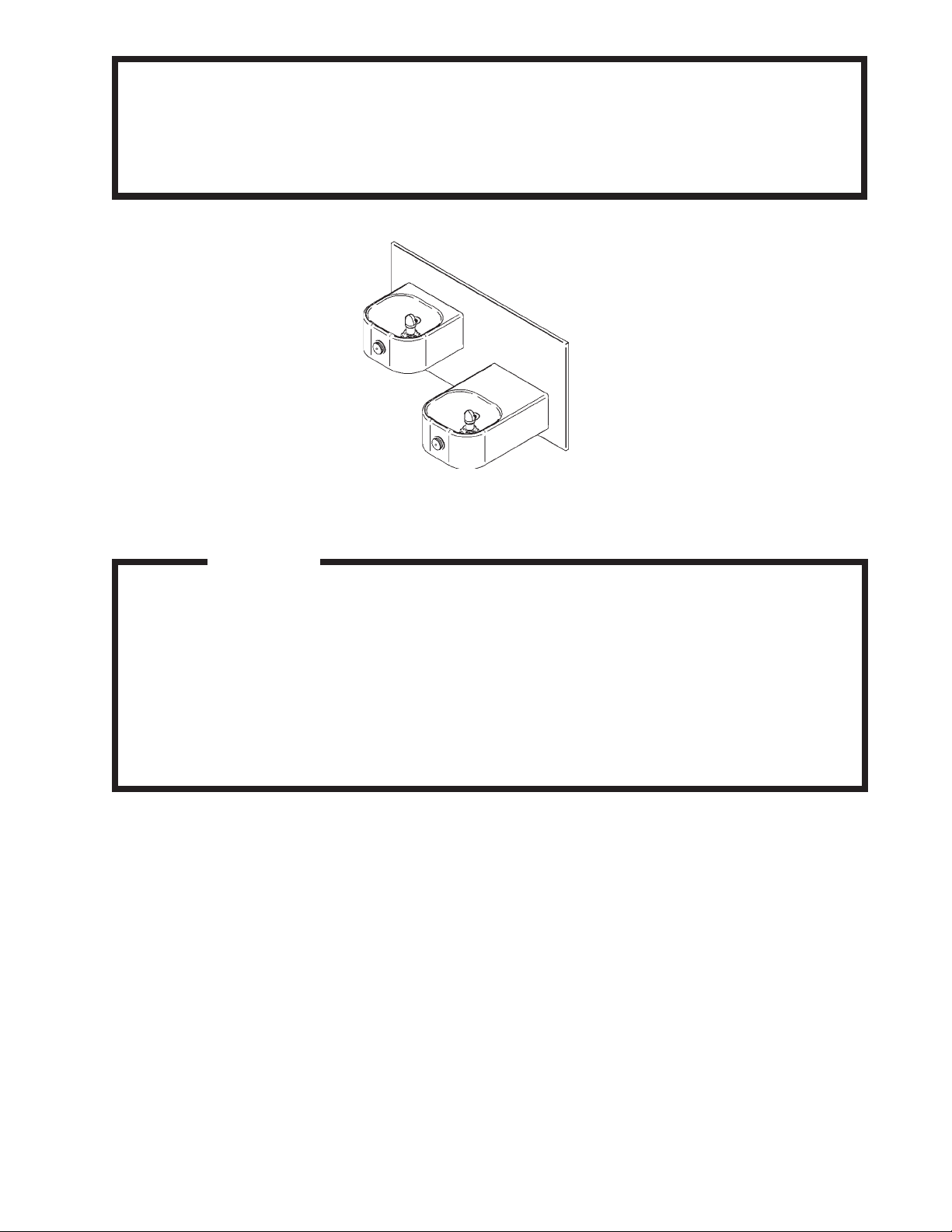
Soft Sides™ Freeze Resistant Fount ain
EDFP217FPC
Installer
T o assure you install this model easily and correctly , PLEASE READ THESE SIMPLE
INSTRUCTIONS BEFORE ST ARTING THE INST ALLA TION. CHECK YOUR INST ALLATION FOR COMPLIANCE WITH PLUMBING , ELECTRICAL AND OTHER APPLICABLE
CODES. After installation, leave these instructions inside the fountain for future reference.
This Freeze Resistant Fountain is shipped in two separate cartons. The second carton(s)
contains the Freeze Resistant Package(s) LKFRB1 that are installed on an interior
heated wall. The interior space must maintain a minimum temperature of 50° F (10° C).
Refer to the Freeze Resistant Package for the rough-in dimensions for installation.
IMPORTANT
ALL SERVICE TO BE PERFORMED BY AN AUTHORIZED SERVICE PERSON
IMPORTANT! INSTALLER PLEASE NOTE.
THE GROUNDING OF ELECTRICAL EQUIPMENT SUCH AS TELEPHONE, COMPUTERS, ETC. TO
WA TER LINES IS A COMMON PROCEDURE. THIS GROUNDING MA Y BE IN THE BUILDING OR MA Y
OCCUR A WA Y FROM THE BUILDING . THIS GROUNDING CAN CAUSE ELECTRICAL FEEDBACK
INTO A FOUNT AIN, CREA TING AN ELECTROLYSIS WHICH CAUSES A METALLIC T ASTE OR AN
INCREASE IN THE METAL CONTENT OF THE WATER. THIS CONDITION IS A VOIDABLE BY USING
THE PROPER MA TERIALS AS INDICA TED. ANY DRAIN FITTINGS PROVIDED BY THE INST ALLER
SHOULD BE MADE OF PLASTIC TO ELECTRICALL Y ISOLA TE THE FOUNT AIN FROM THE BUILDING
PLUMBING SYSTEM.
PAGE 1
97730C (Rev. L - 6/08)
Page 2
EDFP217FP*B EDFP217FPRA*B
The freeze resistant package must be mounted on an interior wall in a heated area. The room temperature of the interior heated area must be 50° F
(10° C) or higher. The freeze resist ant package may be surface or recessed mounted. If recess mounted the surface of the cover must be flush
with the interior wall surface. The package is furnished with screws for mounting the cover to the box. If the box is recess mounted, do not
fasten the top and bottom of the cover to the box. Use the holes on the front only.
1. Fountains using the MPW Mounting Plate refer to Fig's. 6 or 8 for hanger bracket location and rough-in dimensions.
NOTE: Review separate installation instructions for details of the MPW Mounting Plate.
Fountains using the MP20 Wall Plate Assy . refer to Fig. 4 for rough-in dimensions.
2. Shown dimensions pertain to installation location (framing must support up to 150 lbs. weight for single fountain and 300 lbs. for dual
fountains). These dimensions are required for compliance with ANSI Standard A1 17.0.
3. Installing back panel.
EDFP217FPC: Refer to Fig. 17 for placement of braces onto back panel. Place the upper edge of the panel above hanger
bracket. Slide the panel down until it engages the hanger bracket. Be sure back panel is firmly engaged before releasing it.
EDFP217FPC w/MP20 Wall Plate Assy .: Place the upper edge of the panel above mounting plate on the wall. Slide the panel down until it
engages the hanger. Be sure back panel is firmly engaged before releasing it.
4. Remove bottom access panel from fountain basin and save the screws.
EDFP217FPC: Install the fountain to the back panel and wall using (4) 5/16 “ x 6” long threaded rods, washers, and nuts (provided).
Tighten securely .
EDFP217FPC w/MP20 Wall Plate Assy .: Install the fountain to the back panel and wall using (4) 5/16" x 3/4" long bolts and washers (provided)
thru holes in back panel. A washer is used on the bottom two (2) holes only . T ighten securely .
5. Assemble the operating cable to the fountain bracket. (Fountain should be mounted to exterior wall) Create a loop in the cable and thread the
free end of the cable through the wall into the freeze resistant box. The adjustment nuts should be in the middle of threaded area on the
operating cable. See Figure 11.
6. Connect free end of operating cable to the valve-operating bracket. The end of the cables must be recessed into the indents on the pivot
brackets. Remove cable free play by adjusting the jam nuts on the ends of the operating cable. See Figure 1 1.
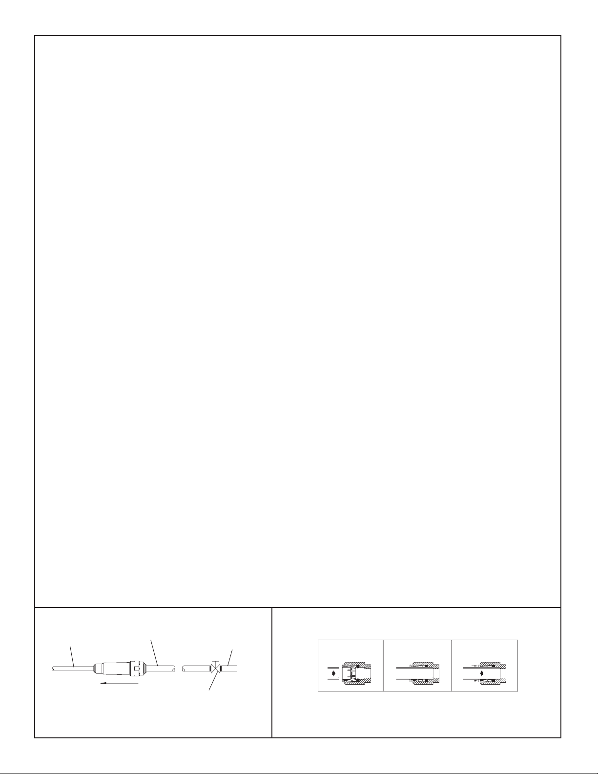
7. Connect water line from fountain bubbler into freeze resistant box. The connection to the box uses a quick connect water fitting. Position the
water line, in the fountain, to drain back into interior mounted box. Any water lef t standing, in the exterior line, can freeze . See Fig. 14.
T o insert tubing, push tube straight into fitting until it reaches a positive stop. T o remove tubing from the fittings, relieve water pressure, push in
on dark gray collar while pulling out on the tubing. See Figure 2.
8. Connect drain and water supply lines to the freeze resistant fountain. Refer to Figure's 3 thru 9 for component positions.
Inline strainer must be used on the inlet water line. See Fig. 1.
Start-up
1. Turn on building water supply and check all connections for leaks. Repair as required.
2. Stream height is factory set at 35 PSI. If stream height needs to be changed adjust the regulator in the freeze resistant package. Clockwise
adjustment raises stream height, counter clockwise adjustment will lower stream.
3. Adjust operating cable as required. Cable system should have a minimal amount of free play to allow for proper valve operation. If the system is
too tight the valve will stay in the on position creating constant water flow. Too much free play will result in non-operation of the valve with the
push-buttons.
4. Note: Water from the drain back tube in the freeze resistant package, will continue to run while the valve is actuated.
5. After cable system is adjusted properly stuf f flexible insulation into any openings between the outside wall and the interior box.
6. Recheck all connections. If all connections are leak free replace cover(s) on the freeze resistant box(es) and fountain(s).
1/4" O.D. TUBE
WATER INLET
NOTE: WA TER FLOW DIRECTION
FIG . 1
97730C (Rev. L - 6/08)
3/8" O.D. UNPLATED
COPPER TUBE CONNECT
COLD WA TER SUPPLY
BUILDING WATER
INLET
SERVICE STOP
(NOT FURNISHED)
FIG . 2
PAGE 2
OPERA TION OF QUICK CONNECT FITTINGS
SIMPLY PUSH IN
TUBE TO ATTACH
TUBE IS
SECURED
IN POSITION
PUSH IN COLLET
TO RELEASE TUBE
PUSHING TUBE IN BEFORE
PULLING IT OUT HELPS TO
RELEASE TUBE
Page 3
EDFP217FP*B EDFP217FPRA*B
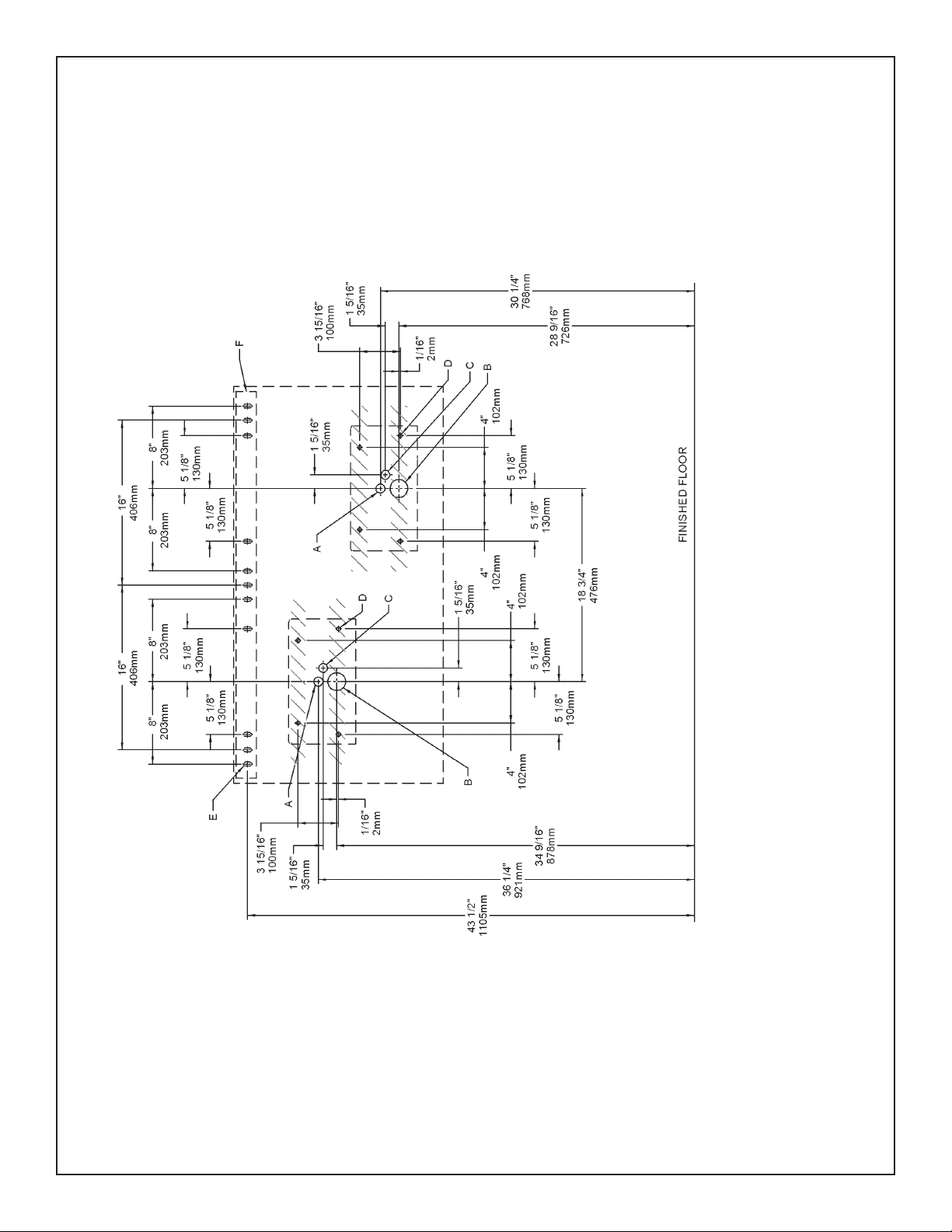
NOTE: REINFORCE WALL IN SHADED AREAS.
EDFP217FP ROUGH-IN
FIG . 3
PAGE 3
LEGEND
A = 7/8" (22mm) DIA. HOLE FOR W A TER SUPPL Y TUBE
B = 1-3/4" (44mm) DIA. HOLE FOR WASTE LINE
C = 7/8" DIA. (22mm) HOLE FOR OPERA TING CABLE
D = MOUNTING BOL T LOCA TIONS (8) (3/8" DIA. NOT PROVIDED)
E = 3/8" (10mm) DIA. SLOTS FOR MOUNTING HANGER TO W ALL
F = WALL HANGER FURNISHED LOOSE
*Note: All dimensions are taken from the finished floor on the the side of
the wall the fountain is installed on.
97730C (Rev. L - 6/08)
Page 4
EDFP217FP*B EDFP217FPRA*B
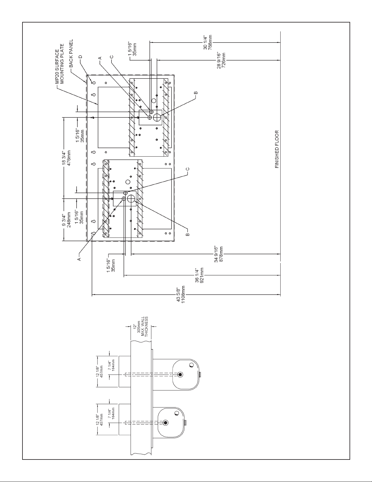
NOTE: REINFORCE WALL IN SHADED AREAS.
EDFP217FP W/MOUNTING PLATE ROUGH-IN
FIG . 4
97730C (Rev. L - 6/08)
PAGE 4
LEGEND
A = 7/8" (22mm) DIA. HOLE FOR W A TER SUPPL Y TUBE
B = 1-3/4" (44mm) DIA. HOLE FOR WASTE LINE
C = 7/8" DIA. (22mm) HOLE FOR OPERA TING CABLE
D = 1/4" (6mm) DIA. HOLE FOR MOUNTING PLA TE TO W ALL
*Note: All dimensions are taken from the finished floor on the the side of
the wall the fountain is installed on.
Page 5

EDFP217FP*B EDFP217FPRA*B
EDFP217FP ROUGH-IN
FIG . 5
PAGE 5
97730C (Rev. L - 6/08)
Page 6

EDFP217FP*B EDFP217FPRA*B
30 1/4"
MPW200
3 1/4"
HANGER BRACKET
82mm
MTG. PLT.
1 5/16"
33mm
768mm
28 9/16"
725mm
32"
A
C
B
16"
406mm
1 5/16"
33mm
813mm
1 5/16"
33mm
A
18 3/4"
476mm
FINISHED FLOOR
C
B
6 5/8"
168mm
D
34 9/16"
36 1/4"
921mm
878mm
FIG . 6
1 5/16"
33mm
BACK PANEL
43 1/2"
1105mm
EDFP217FP W/MPW200 MOUNTING PLATE ROUGH-IN
97730C (Rev. L - 6/08)
7 1/4"
184mm
12 1/8"
307mm
7 1/4"
184mm
12 1/8"
307mm
LEGEND
A = 7/8" (22mm) DIA. HOLE FOR W A TER SUPPL Y TUBE
B = 1-3/4" (44mm) DIA. HOLE FOR WASTE LINE
C = 7/8" DIA. (22mm) HOLE FOR OPERA TING CABLE
D = 1/4" (6mm) DIA. HOLE FOR MOUNTING PLA TE TO W ALL
*Note: All dimensions are taken from the finished floor on the the side of
12"
305mm
MAX. WALL
PAGE 6
THICKNESS
the wall the fountain is installed on.
Page 7

EDFP217FP*B EDFP217FPRA*B
34 9/16"
878mm
HRFSFR
MPW200 MTG. PLT.
REF. SEPARATE
INSTALLATION
INSTRUCTIONS
FOR DETAILS
5/8"
16mm
28 9/16"
725mm
HRFEFR
23 1/2"
597mm
HRFSFR
20"
508mm
HRFSFR
17 1/2"
444mm
HRFEFR
14"
355mm
HRFEFR
3 5/8"
13"
330mm
HRFEFR
91mm
2 5/8"
66mm
EDFP217FP W/MPW200 MOUNTING PLATE ROUGH-IN
12 1/4"
311mm
HRFSFR
18"
457mm
HRFEFR
FINISHED WA LL
12"
305mm
MAX. WALL
THICKNESS
FIG . 7
FINISHED FLOOR
3 13/16"
38 1/2"
978mm
12 1/8"
6 5/8"
97mm
308mm
168mm
6 1/2"
165mm
HRFEFR
27"
686mm
ADA REQUIREMENT
PAGE 7
33"
838mm
HRFSFR
97730C (Rev. L - 6/08)
Page 8

EDFP217FP*B EDFP217FPRA*B
28 9/16"
725mm
30 1/4"
768mm
43 1/2"
1105mm
34 9/16"
878mm
36 1/4"
921mm
1 5/16"
33mm
1 5/16"
33mm
1 5/16"
33mm
1 5/16"
33mm
3 1/4"
82mm
16"
406mm
32"
813mm
6 5/8"
168mm
18 3/4"
476mm
A
A
B
B
C
C
D
BACK PANEL
HANGER BRACKET
MPW200
MTG. PLT.
FINISHE D FL O OR
FIG . 8
EDFP217FPRAC W/MPW200 MOUNTING PLATE ROUGH-IN
7 1/4"
184mm
12 1/8"
307mm
7 1/4"
184mm
12 1/8"
307mm
97730C (Rev. L - 6/08)
12"
305mm
MAX. WALL
THICKNESS
PAGE 8
LEGEND
A = 7/8" (22mm) DIA. HOLE FOR W A TER SUPPL Y TUBE
B = 1-3/4" (44mm) DIA. HOLE FOR WASTE LINE
C = 7/8" DIA. (22mm) HOLE FOR OPERA TING CABLE
D = 1/4" (6mm) DIA. HOLE FOR MOUNTING PLA TE TO W ALL
*Note: All dimensions are taken from the finished floor on the the side of
the wall the fountain is installed on.
Page 9

EDFP217FP*B EDFP217FPRA*B
34 9/16"
MPW200 MTG. PLT.
REF. SEPARATE
INSTALLATION
INSTRUCTIONS
FOR DETAILS
5/8"
16mm
878mm
HRFSFR
28 9/16"
725mm
HRFEFR
23 1/2"
597mm
HRFSFR
20"
508mm
HRFSFR
17 1/2"
444mm
HRFEFR
14"
355mm
HRFEFR
3 5/8"
13"
330mm
HRFEFR
91mm
2 5/8"
66mm
EDFP217FPRAC W/MPW200 MOUNTING PLATE ROUGH-IN
12"
305mm
MAX. WALL
12 1/4"
311mm
HRFSFR
FINISHED WALL
18"
457mm
HRFEFR
THICKNESS
FIG . 9
FINISHED FLOOR
20 3/8"
518mm
HRFSFR
33"
838mm
38 1/2"
978mm
3 13/16"
97mm
12 1/8"
308mm
6 5/8"
168mm
6 1/2"
165mm
PAGE 9
HRFEFR
27"
686mm
ADA REQUIREMENT
97730C (Rev. L - 6/08)
Page 10

EDFP217FP*B EDFP217FPRA*B
CABLE SHEA TH ADJUSTMENT
T o Increase Free Play
T o Reduce Free Play
FIG . 12
FIG . 10
See Fig. 10
FIG . 1 1
See Fig. 12
FIG . 13
97730C (Rev. L - 6/08)
FIG . 14
9
FIG . 15
21
3
PAGE 10
Page 11

EDFP217FP*B EDFP217FPRA*B
10
11
12
13
14
15
16
17
18
19
20
21
22
23
24
NS
NS
NS
1
2
3
4
5
6
7
8
9
P ARTS LIST
P ART NO.ITEM NO.
100322740560
75661C
15009C
28823C
27945C
27946C
40045C
40206000
45392C
45662C
45663C
50198C
51667C
55919C
70425C
28782C
28783C
55000661
55000665
28250C
28252C
75672C
72000833
28234C
56280C
56092C
27090C
75523C
DESCRIPTION
GASKET
SCREW-#8 X 50 PINNED TORX
NIPPLE ASSY
BRACKET-REGULA TOR MOUNTING
BRACKET-BASIN
BRACKET-BASIN PIVOT
HEX NUT 1-5/16
RETAINER
BUBBLER
PUSH BUTTON
SLEEVE-PUSH BUTTON GUIDE
SNAP BUSHING
BUMPER-REG . V AL VE ASSY
PUSH BUTTON (EXTENSION)
PIVOT ROD
FOUNTAIN ARM - SHORT
FOUNTAIN ARM - LONG
BOTTOM COVER PLA TE - SHORT
BOTTOM COVER PLATE - LONG
BACK PANEL RH ADA
BACK PANEL LH ADA
CAP SCREW
WASTE ARM ASSY
BRACE - CHANNEL
EDGE TRIM
POLY TUBING-CUT TO LENGTH
BRKT-HANGER P ANEL
BIT - PINNED TORX
FIG . 16
SEE FIG. 18
FIG . 17
SEE FIG. 15
24
22, 18
1
20
2, 17
20
23
FIG . 18
1 1, 19
16
Installing back panel: When installing back
panel (Item 20) without mounting plate accessory
MP20 or MP20RA, attach (4) channel braces
(Item 23) as shown in Fig. 17. Remove the
protective backing from the tape installed on the
brace. Line up the corresponding holes in the
brace and back panel and press firmly in place.
13
6
7
5
4
14
8
15
12
12
10
24
FOR PARTS, CONTACT YOUR LOCAL DISTRIBUTOR OR CALL 1.800.323.0620
ELKA Y MANUFACTURING COMPANY • 2222 CAMDEN COURT • OAK BROOK, IL 60523 • 630.574.8484
PAGE 11
97730C (Rev. L - 6/08)
 Loading...