

Page 1
EDFP110/114/117FPC
Installation/Care/Use Manual
EDFP110FPC EDFP114FPC EDFP117FPC
®
Swirlflo
Installer
T o assure you install this model easily and correctly , PLEASE READ THESE SIMPLE
INSTRUCTIONS BEFORE ST ARTING THE INST ALLATION. CHECK YOUR INST ALLATION FOR COMPLIANCE WITH PLUMBING, ELECTRICAL AND OTHER APPLICABLE
CODES. After installation, leave these instructions inside the fountain for future reference.
This Freeze Resistant Fountain is shipped in two separate cartons. The second carton
contains the Freeze Resistant Package LK616A that is installed on an interior heated
wall. Refer to the Freeze Resistant Package for the rough-in dimensions for installation.
Freeze Resistant Fount ains
IMPORTANT
ALL SERVICE TO BE PERFORMED BY AN AUTHORIZED SERVICE PERSON
IMPORTANT! INSTALLER PLEASE NOTE.
THE GROUNDING OF ELECTRICAL EQUIPMENT SUCH AS TELEPHONE, COMPUTERS, ETC. TO
WA TER LINES IS A COMMON PROCEDURE. THIS GROUNDING MA Y BE IN THE BUILDING OR MA Y
OCCUR A WA Y FROM THE BUILDING . THIS GROUNDING CAN CAUSE ELECTRICAL FEEDBACK
INTO A FOUNT AIN, CREA TING AN ELECTROLYSIS WHICH CAUSES A METALLIC T ASTE OR AN
INCREASE IN THE METAL CONTENT OF THE WATER. THIS CONDITION IS A VOIDABLE BY USING
THE PROPER MA TERIALS AS INDICA TED. ANY DRAIN FITTINGS PROVIDED BY THE INST ALLER
SHOULD BE MADE OF PLASTIC TO ELECTRICALL Y ISOLA TE THE FOUNT AIN FROM THE BUILDING
PLUMBING SYSTEM.
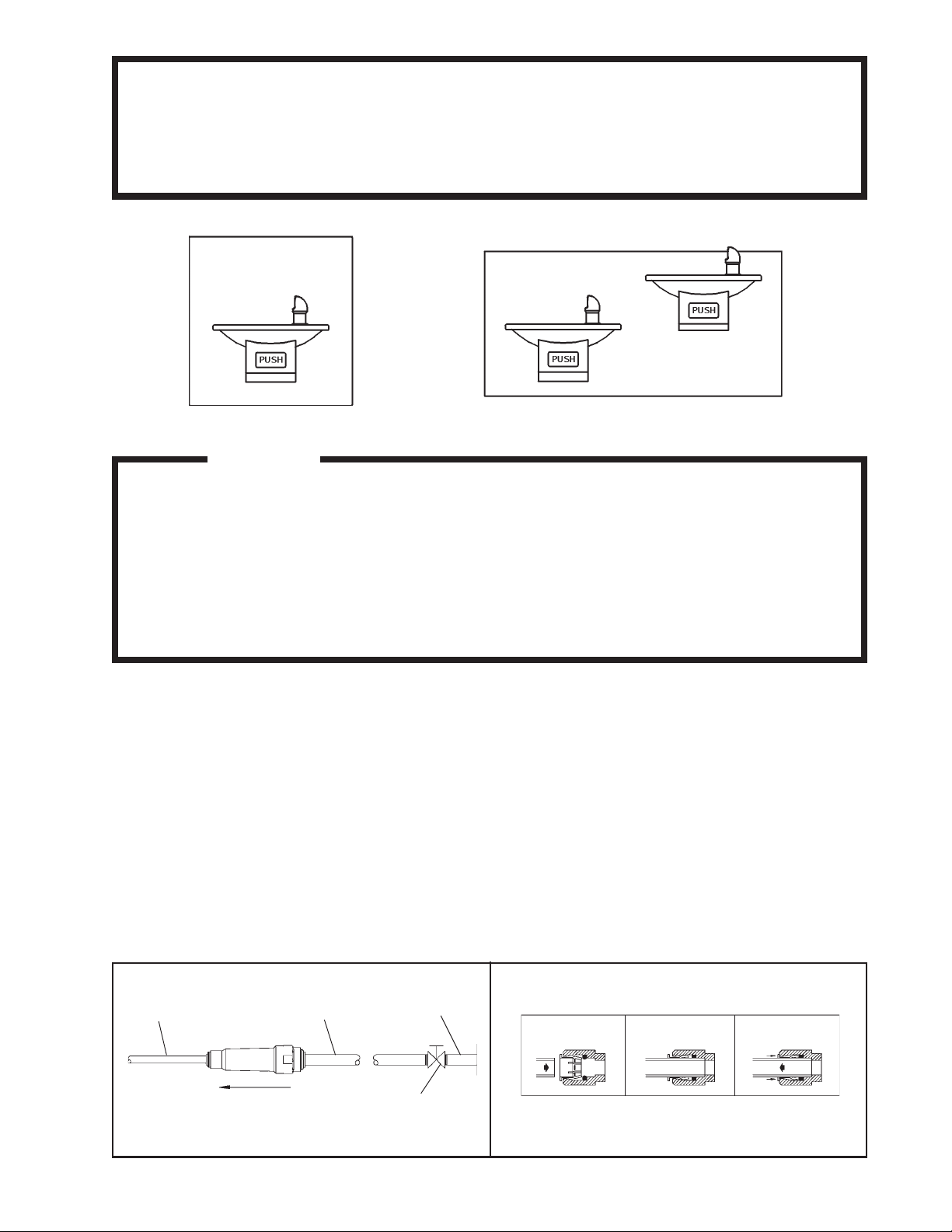
1/4" O.D. TUBE
WATER INLET
TO COOLER
3/8" O.D. UNPLATED
COPPER TUBE CONNECT
COLD WATER SUPPLY
NOTE: WATER FLOW
DIRECTION
BUILDING WATER
INLET
SERVICE STOP
(NOT FURNISHED)
FIG. 1
PAGE 1
OPERA TION OF QUICK CONNECT FITTINGS
SIMPLY PUSH IN
TUBE TO ATTACH
FIG. 2
TUBE IS
SECURED
IN POSITION
PUSH IN COLLET
TO RELEASE TUBE
PUSHING TUBE IN BEFORE
PULLING IT OUT HELPS TO
RELEASE TUBE
97030C (Rev. F - 12/04)
Page 2
EDFP110/114/117FPC
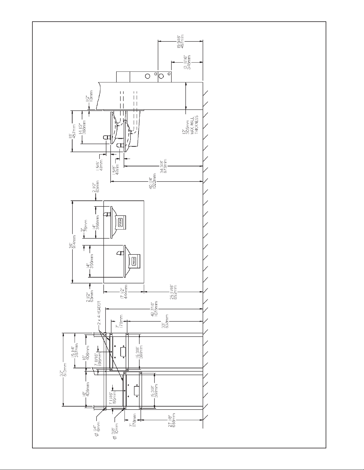
EDFP1 17FPC ROUGH-IN
FINISHED FLOOR *
FIG. 3
97030C (Rev. F - 12/04)
PAGE 2
1. Wall should already be framed for the fountain using dimensions shown in Fig. 3. Shown dimensions pertain to installation location.
These dimensions are required for compliance with ANSI Standard A1 17.1. (and ADA) (Framing shown for reference only).
2. Attach the hanger bracket and panel mounting bracket(s)s to the wall as shown in Fig. 3. Use bolts and flat washers (not provided). Tighten securely.
3. Install the back panel. Place the upper edge of the p anel above the hanger on the wall. Slide the panel down until it engages the hanger . Be sure p anel is
firmly engaged before releasing it.
4. Remove bottom cover(s) from fountain(s) and save the screws. Assemble push rod(s) to fountain(s). See Fig. 6. (Push rods provided with freeze
resistant boxes)
5. Install the fountain(s) to the back p anel and panel mounting bracket(s) using bolt s (provided). T ighten securely .
6. Attach drain tube(s) (supplied with freeze-resistant box) to fountain(s) and cut to required length using the freeze resistant box as a guide.
7. Install freeze resistant box - see box instructions.
8. Install a service stop (not provided) and make water supply connection from the stop to the strainer(s) in the freeze resistant box.
9. Connect fountain water line to freeze resistant box - see box instructions. Replace bottom cover(s).
*NOTE: All dimensions are taken from the finished floor on the side of the wall that the fountain is installed on.
Page 3

EDFP110/114/117FPC
EDFP1 10/1 14FPC ROUGH-IN
FIG. 4
FINISHED FLOOR *
PAGE 3
*NOTE: All dimensions are taken from the finished floor on the side of the wall that the fountain is installed on.
97030C (Rev. F - 12/04)
Page 4

EDFP110/114/117FPC
P ARTS LIST
ITEM
NO.
1
2
3
4A
4B
5A
5B
6A
6B
7
8
9
10
11
12
13
14
15
16
17
NS
NS
NS
* PAR TS ARE SUPPLIED WITH FREEZE RESIST ANT BOX
PART
NO.
21705C
28322C
21810C
21822C
21823C
21845C
21846C
27314C
27315C
98118C
100322740560
15009C
50198C
55001026
70002C
70410C
70426C
75555C
*75559C
75570C
27089C
55000792
27259C
75520C
DESCRIPTION
CLIP-PUSH ROD
BRACKET-PUSH BAR MTG .
PUSH BAR ASSY
FTN BODY&SHELL EDFP1 10C
FTN BODY&SHELL EDFP1 14C
COVER PLATE EDFP1 10C
COVER PLATE EDFP1 14C
PANEL-BACK EDFP1 17FPC
PANEL-BACK EDFP1 10/1 14FPC
BUBBLER ASSEMBL Y
GASKET
NIPPLE ASSY
BUSHING-SNAP
BASIN
SCREW-#10 X .50 HHSM
ROD-PIVOT
SCREW #8-32 X .25 THMS
CLIP -.125 STUD LOCK
PUSH ROD ASSY
SCREW # 10 X .50 PINNED TORX
HANGER BRACKET EDFP1 10/114FPC
HANGER BRACKET EDFP1 17FPC
BRKT ASSY -PANEL MOUNTING
BIT-PINNED TORX
7
8
9
FIG. 5
11
4A, 5A
6A
SEE FIG. 5
SEE FIG. 6
17
4B, 5B
17
10
15
2
16
12
1
3
13
ELKAY MANUFACTURING COMP AN Y • 2222 CAMDEN COURT • OAK BROOK, IL 60523 • 630.574.8484
97030C (Rev. F - 12/04)
14
FIG. 6
FOR PARTS, CONT ACT YOUR LOCAL DISTRIBUTOR OR CALL 1.800.323.0620
PAGE 4
 Loading...